Molding and Casting
Hero Shots
Click Here for Our Group Assignment
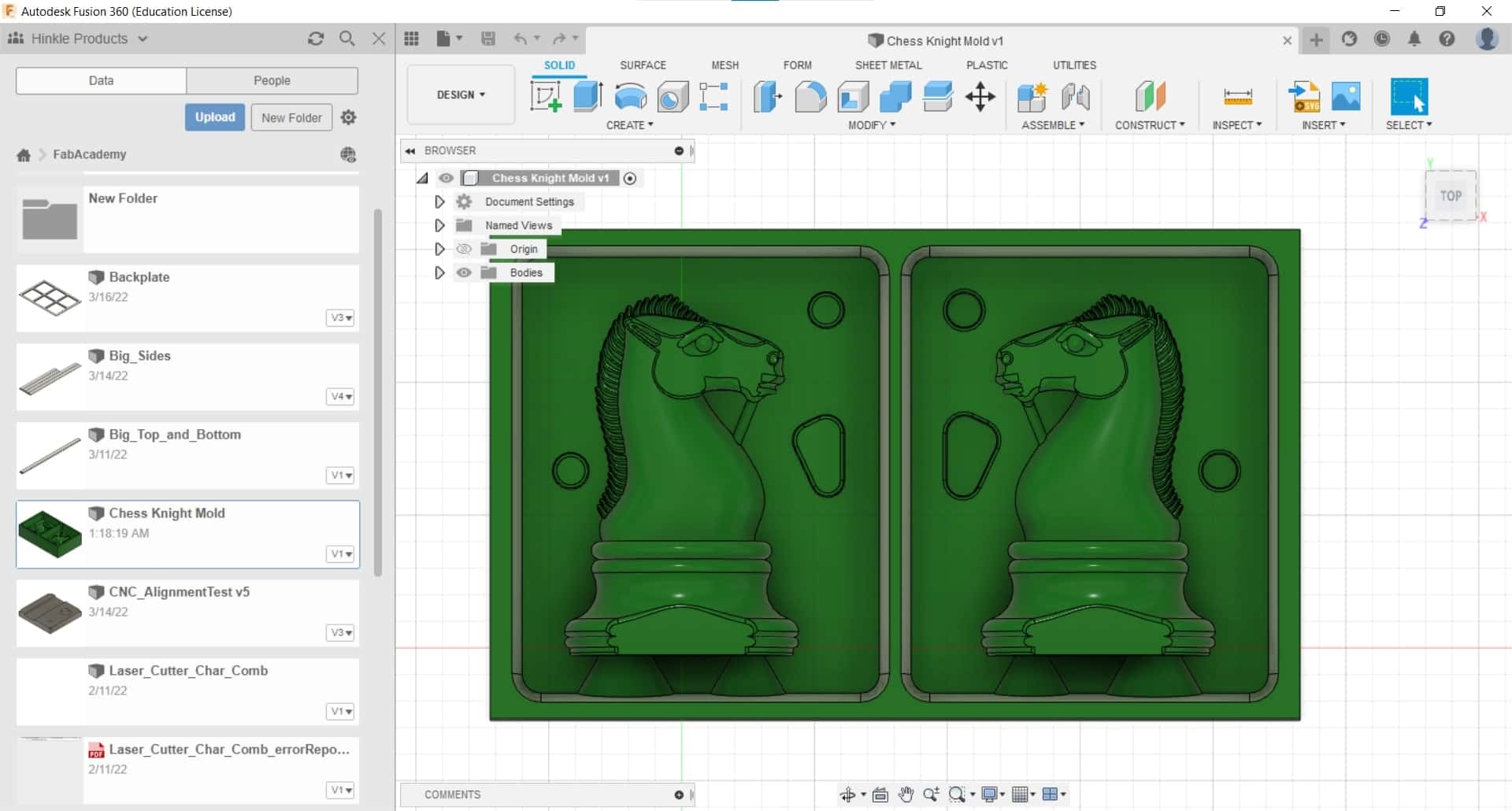
My Knight
File Downloads From This Week
Two Part Wax Mold
CAD of Mold
Initial Reaction
This week is a bit of a detour from the other topics, but I am excited. I have a little bit of experience with molding and casting (two epoxy resin casts and two soft metal casts), but I have never machined a mold or worked with two part silicone and I am looking forward to the possibilities. As usual, Neil walked us through many of the available options for technologies, materials, software and vendors, as well as briefly explaining good practices and safety protocols. The assignment this week is to design a mold based on the stock and tools we have at our disposal; to CNC mill it using a CAM with 3D cutting operations; and then to use the mold to cast parts.
After Local Workshop
We had a short and sweet local workshop this week. Ahmed walked us through the differences between the 2D and 3D workflows for creating the CAM in Fusion 360 and he gave us some tips and tricks for casting from his own experience. Then we were introduced to the materials that we have available (a single block of machining wax for each of us, four pounds of a two-part silicone, and two kilos of a two-part polyurethane casting resin (datasheet here) for the three of us to share). Toward the end of the session, Marcello showed us some of his own molding and casting projects and offered a few useful insights as well. I am excited to get started!
Data Sheet Highlights
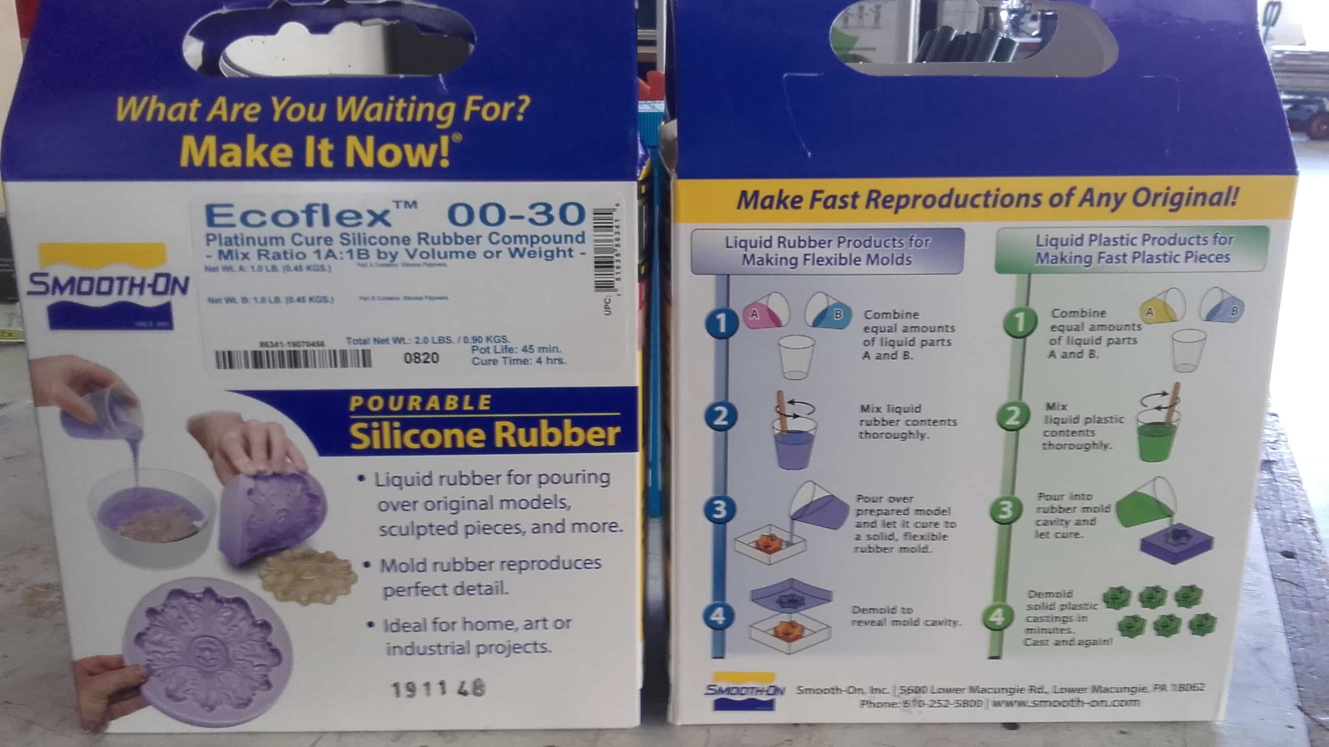
Ecoflex 00-30
- Mix Ratio by Weight or Volume: 1A:1B
- Pot Life: 45 minutes
- Cure Time: 4 hours
- Shore Hardness: 00-30
- Specific Gravity: 1.07 g/cc
- Specific Volume: 26.0 cu. in./lb.
- Tensile Strength: 200 psi
- 100% Modulus: 10 psi
- Elongation @ Break: 900 %
- Die B Tear Strength: 38 pli
- Color: Translucent
- Useful Temperature (min): -65 °F
- Useful Temperature (max): 450 °F
- Shrinkage: .001 in. / in.
- Mixed Viscosity: 3,000 cps
Resin
- Mixing Ratio: 1A:2B
- Mixed Viscosity (25 °C): 325 mPa∙s
- Density (20 °C): 1.15 g/cm3:
- Pot Life (25°C): 5 minutes
- Demouldable After (70 °C): 60 minutes
- Shore Hardness (DIN 53505): 82
- Colour (cured): White
- Recommended Layer Thickness: 5 mm
- Tensile Strength (DIN 53455): 71 MPa
- Tensile Elongation (DIN 53455): 15%
- Flexural Strength (DIN 53452): 99 MPa
- Flexural Modulus (DIN 53457): 2,300 MPa
- Dimensional Stability Under Heat (110 x 13 x 6mm): 105°C
- Impact Strength After 2 h @ 80 °C (DIN 51230): >35 KJ/m2
- Linear Dimensional Change (500 x 50 x 3mm): 0.3 %
Making the Mold
CAD Design
Finding a Model
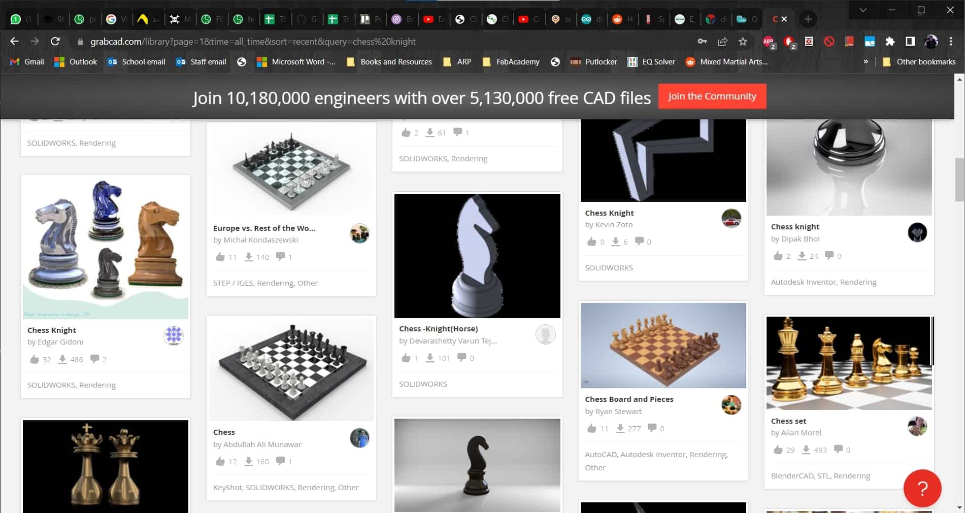
I like playing chess with my dad so I decided to make a chess piece. My favorite piece was always the knight, so that's what I decided to make. I jumped on GrabCAD and found a model I liked.
Not Great
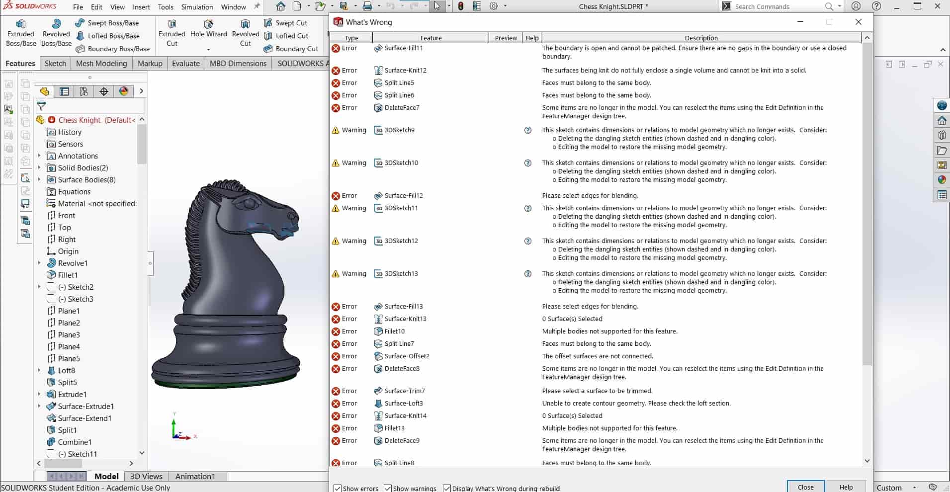
And, as is sometimes the case with free CAD models from the internet, when I opened it I discovered a few dozen errors and broken features...
Good Enough
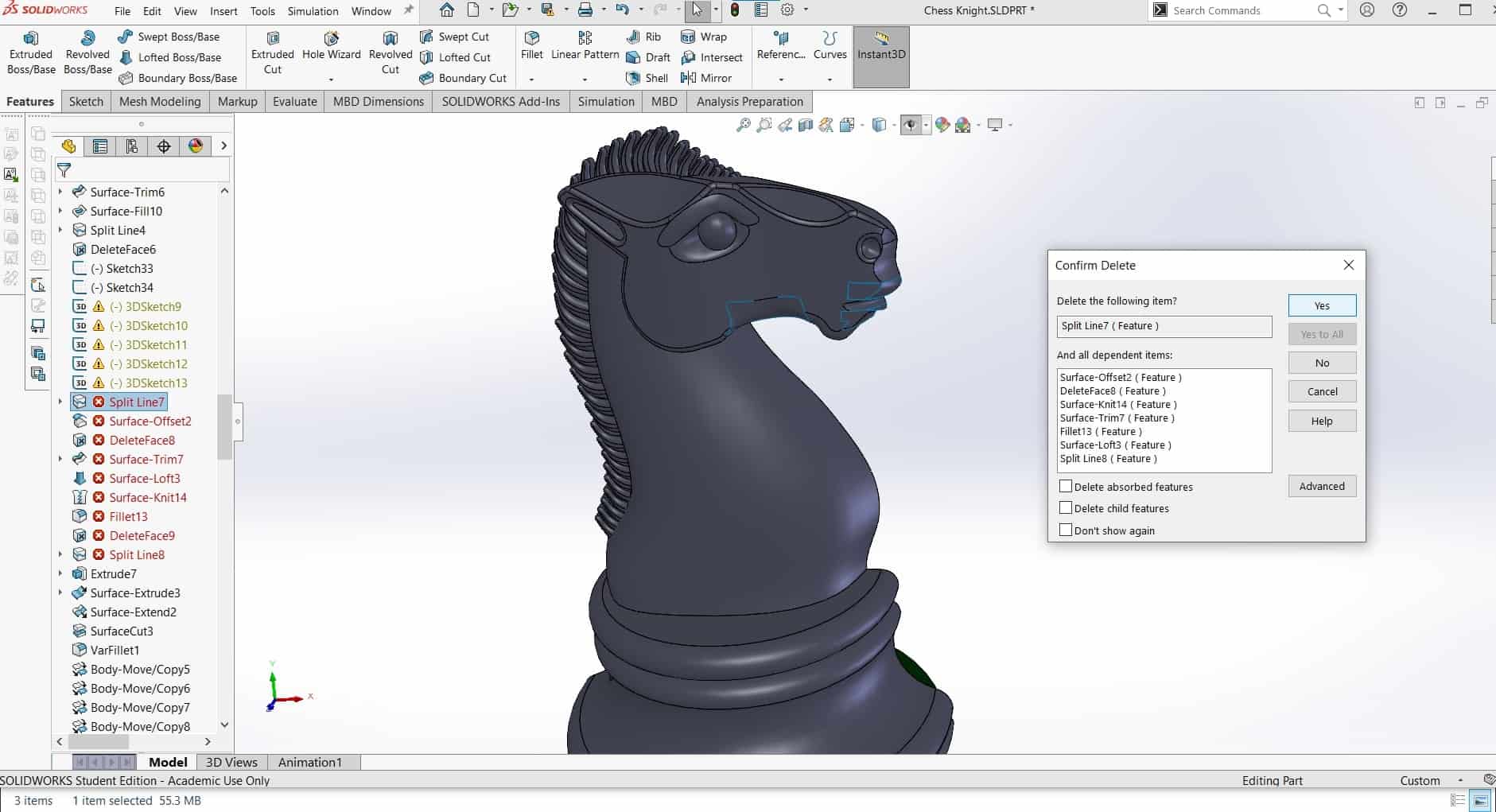
...but it had the geometry I wanted...and even though it was sloppy work, at least most of it had already been done by the maker, instead of myself. So I started deleting broken things that were unnecessary and repairing the model as needed so I could rebuild and start making the mold.
Missing Some Spots
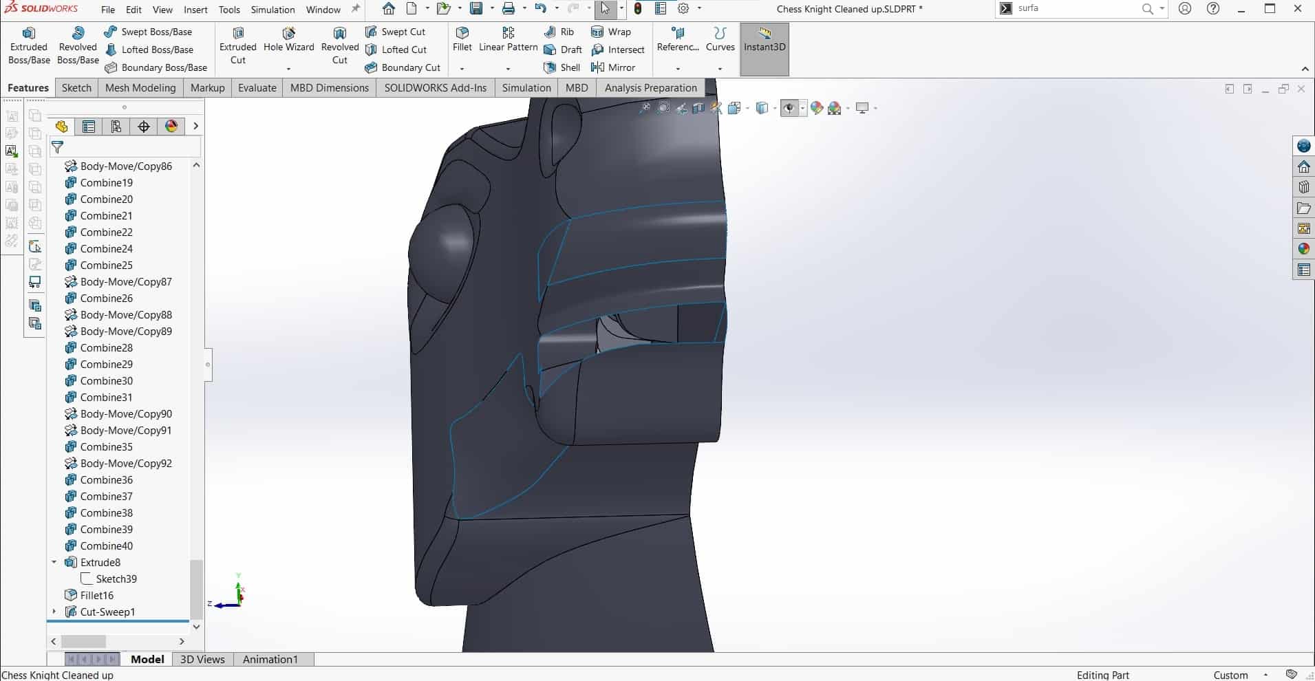
Despite all the deletion, most of the model was still intact and I just needed to recreate a few surfaces.
New 3D Sketches
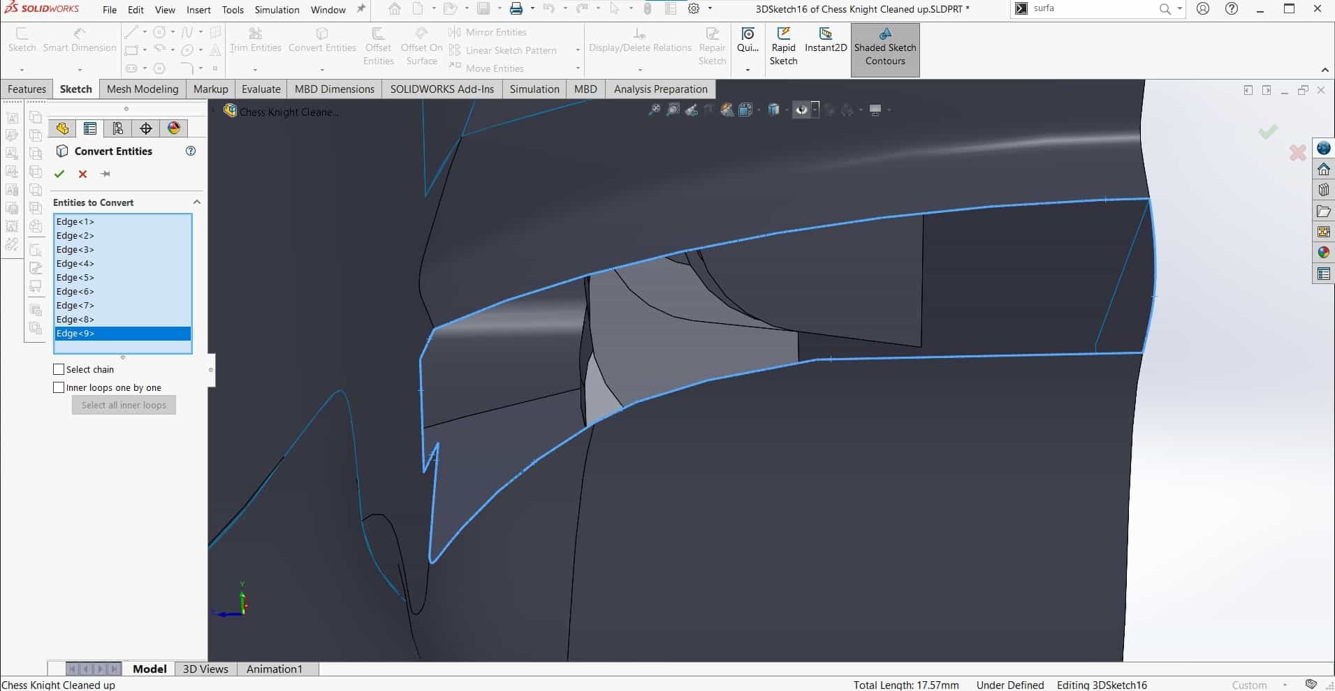
I started by converting the outlines into new 3D sketches using the Convert Entities tool.
Fill Surface
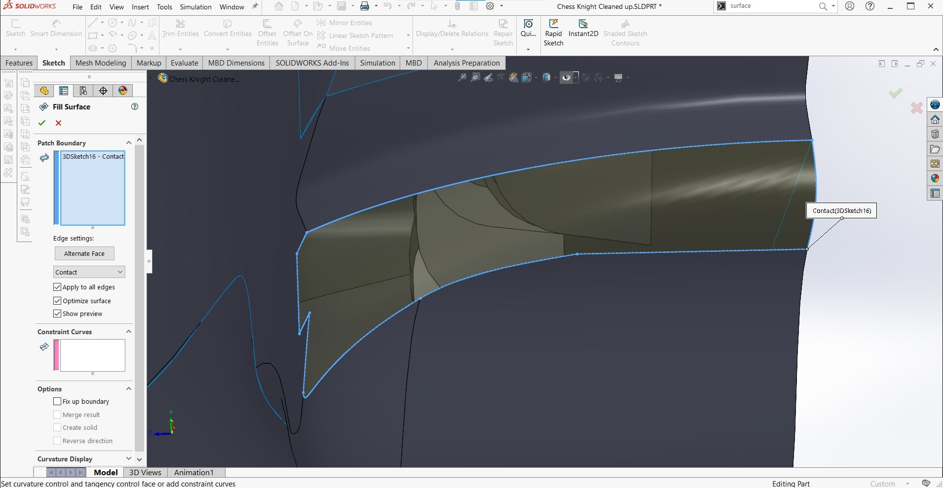
Then I used those 3D sketches and the Fill Surface tool to add material where I needed it.
Knit Surfaces
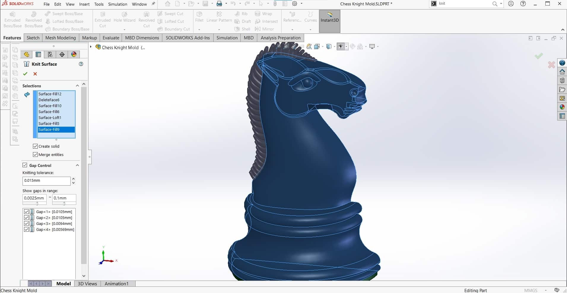
Once I had surfaces everywhere I wanted, I used the Knit Surfaces tool to connect them altogether.
Combine
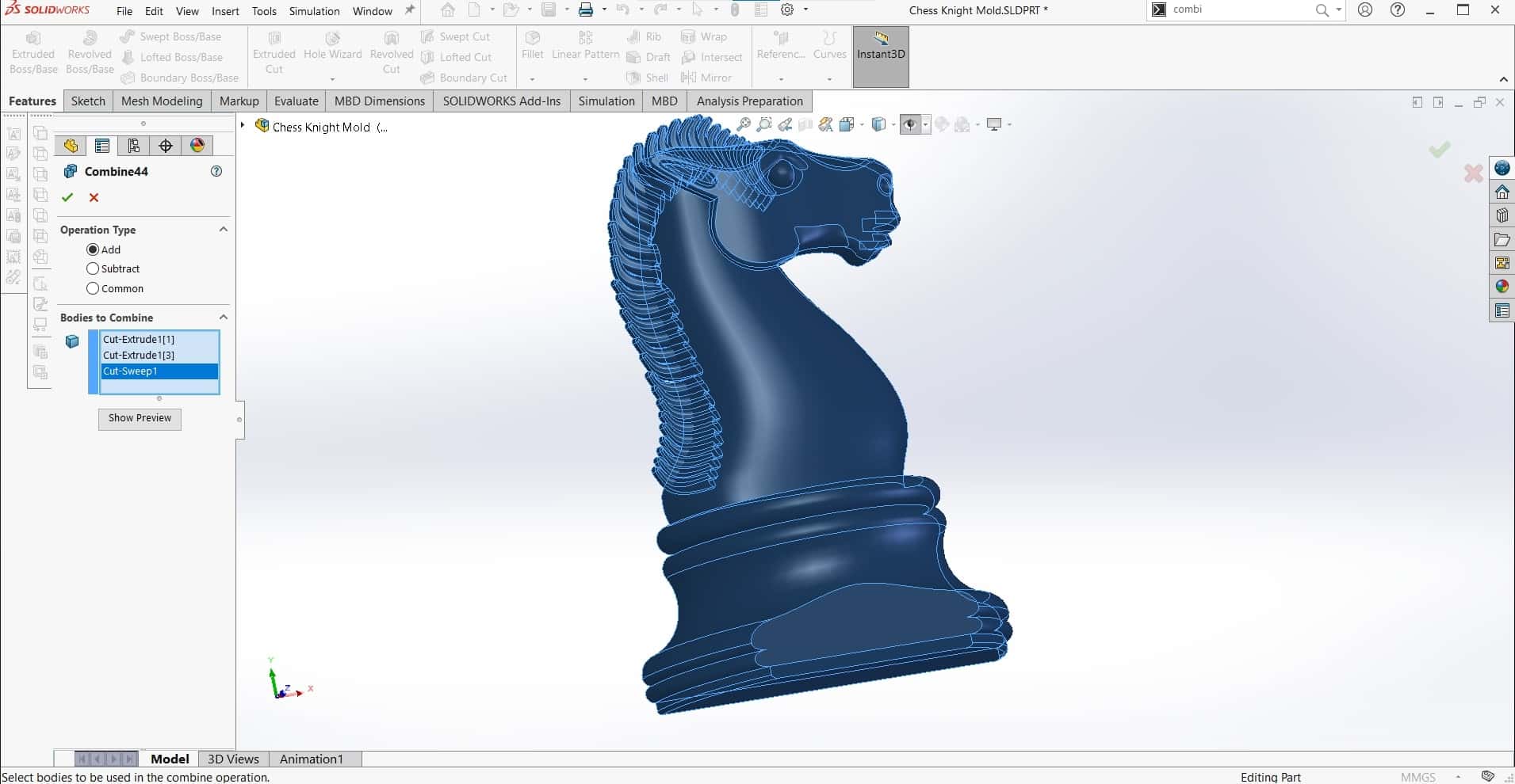
And then I used the Combine tool to turn all the surfaces and extrudes into one solid body.
Fixed
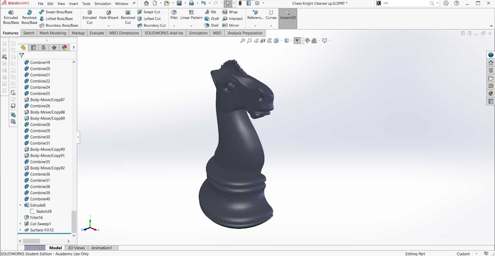
Finally everything was repaired and I was ready to build the mold around the model. I started by cutting off a bit of the base off so the part wouldn't be so deep since our detailing tools only stick out of the collet about 20 mm.
Let the Mold Begin
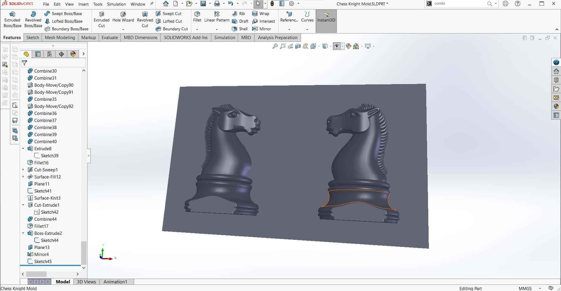
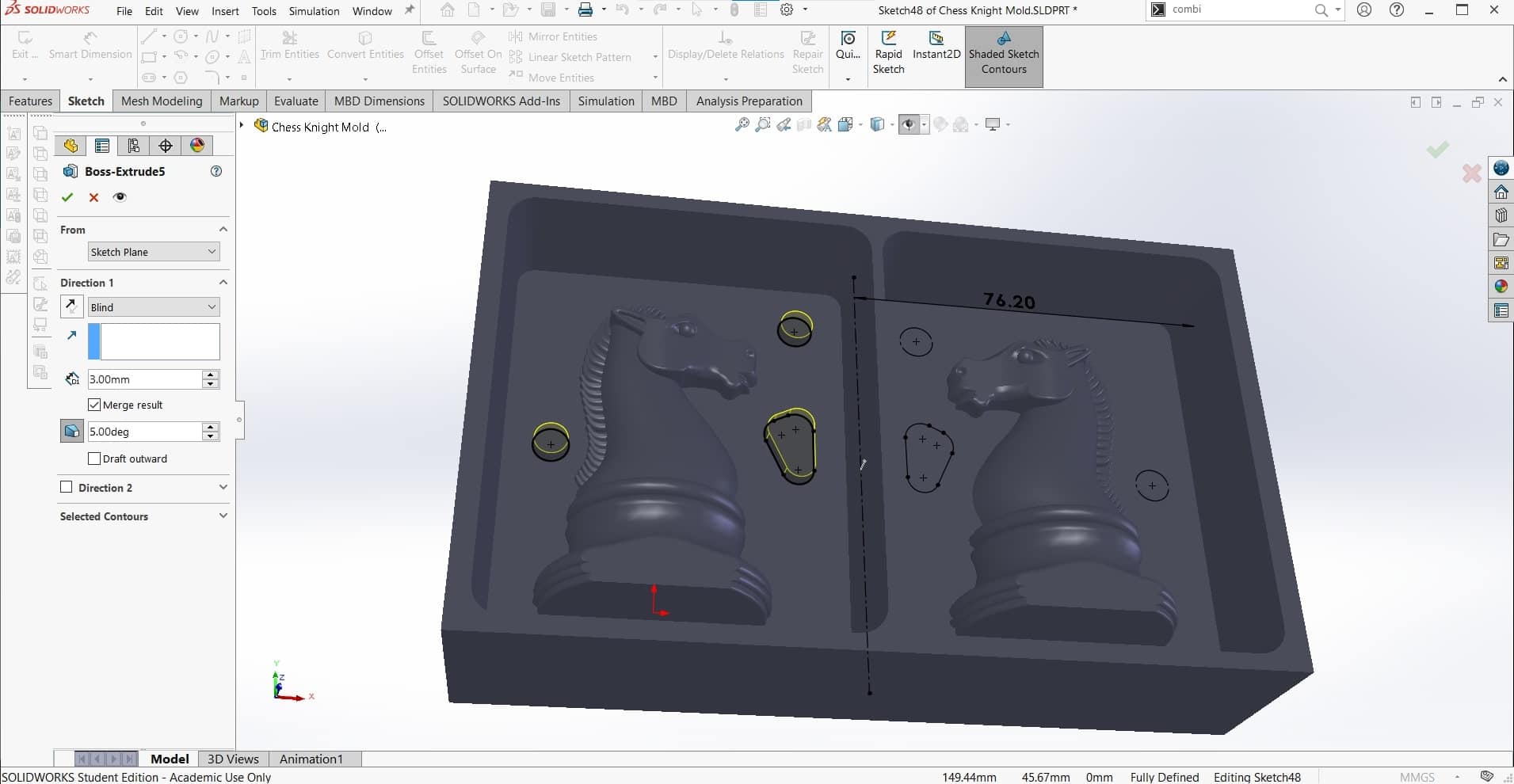
Then I mirrored the part so I would have both sides of the mold, and finally I extruded the bottom of the wax block using the dimensions from the box.
Walls
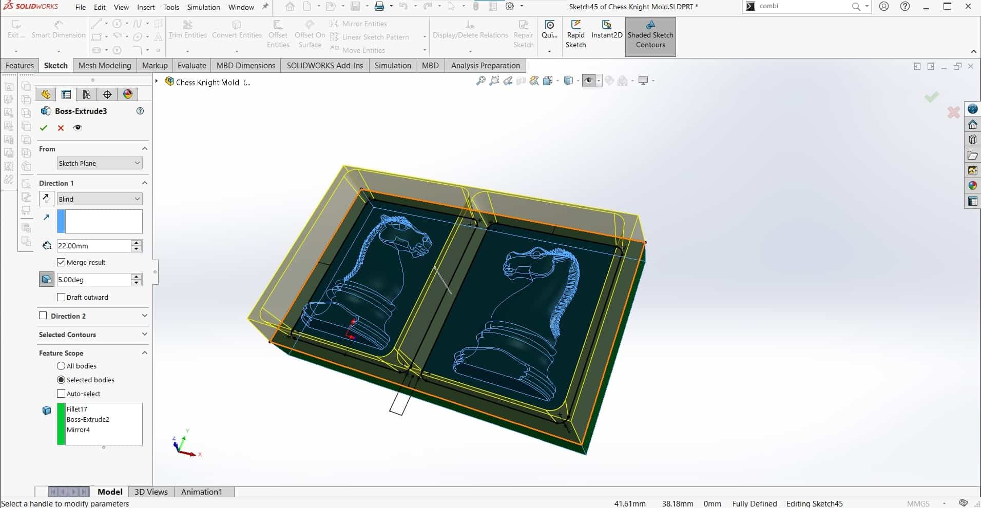
Next I extruded the sides of the mold. I used a 7° draft angle for the walls. I would have liked to use a larger angle, but the block wasn't big enough to to that AND to leave enough room for my biggest tool to pass through, so I chose to make room for the tool.
Sketch for Registration Features
Similarly, I used the width of the toolpaths to define where I would add registration features as well as their geometry. Again, I would have liked to use a different method here, to nest one part of the mold inside the other, instead of simple "innies and outties" but once again, the size of the stock did not permit it.
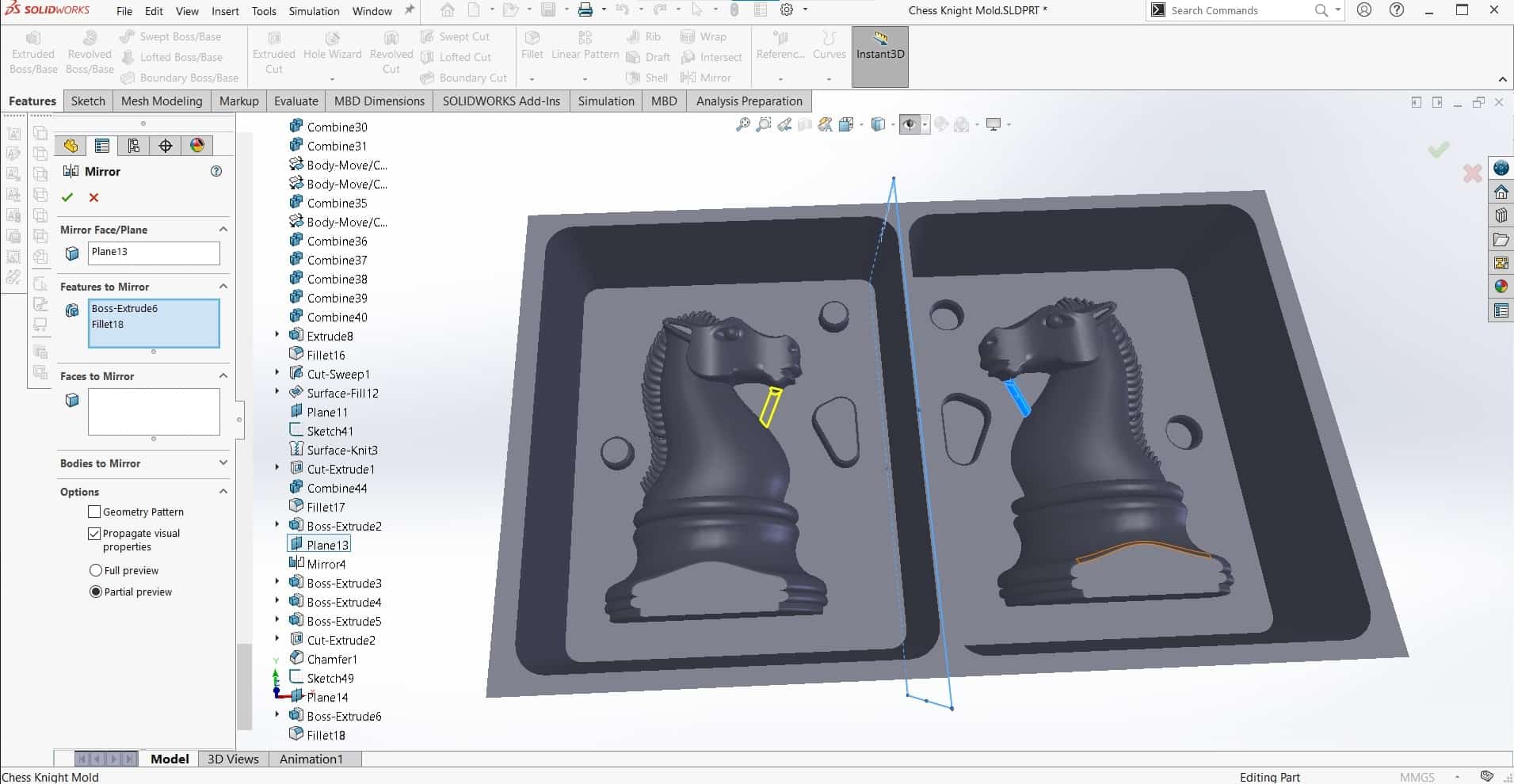
Mirror Sketch
I made another sketch using Mirror.
Innies and Outties
And then Boss Extruded one and Cut Extruded the other, both also with a 7° draft angle.
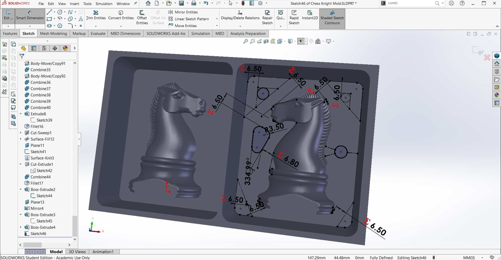
Chamfers
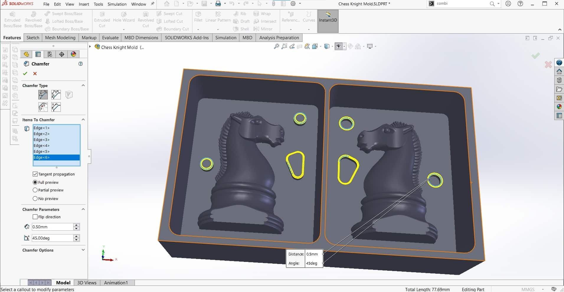
And then finished off the new features with some chamfers to assist in closing the casting together.
Trouble Spot
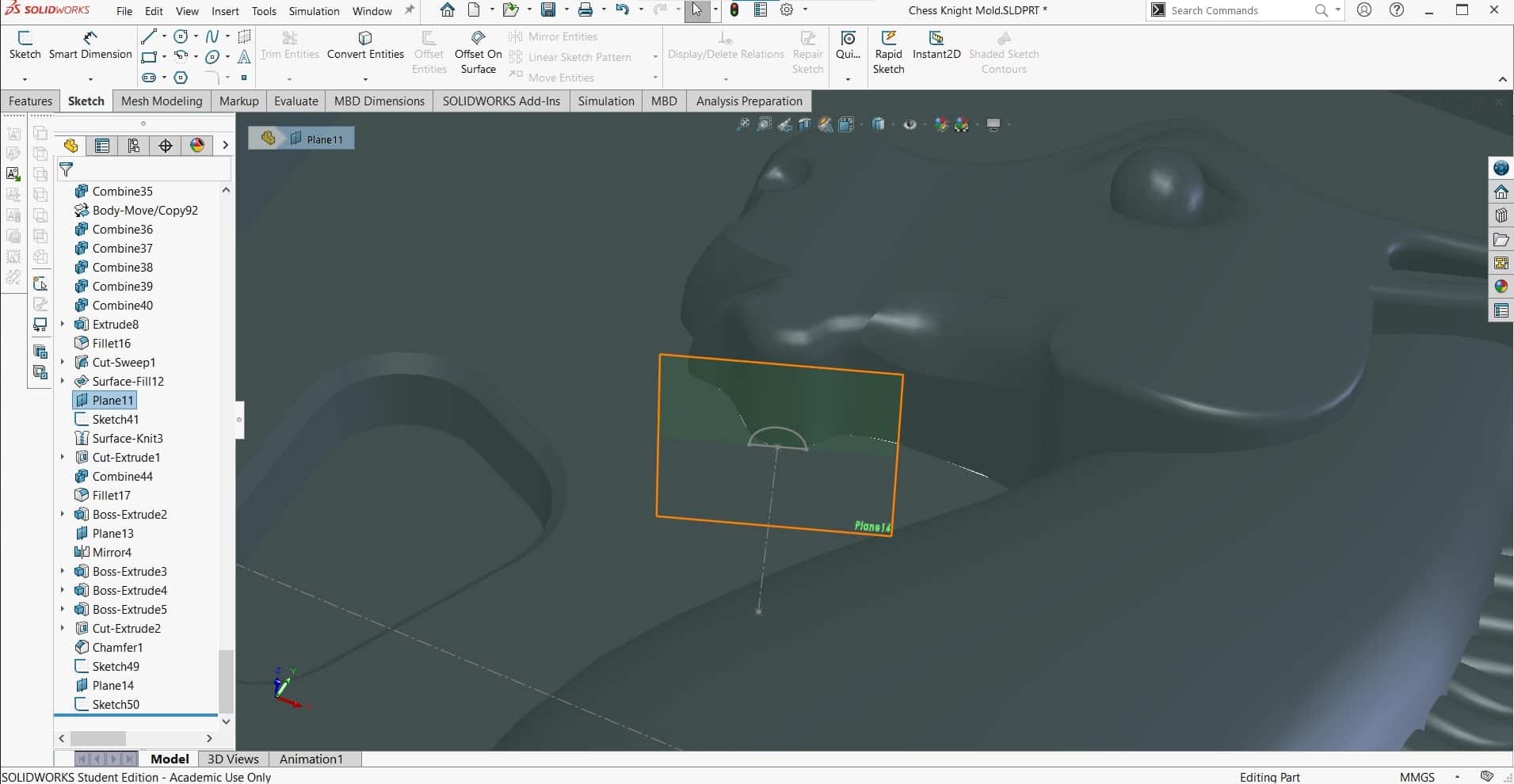
I am planning to pore the resin material with the knight upside down, so I needed some way for material to reach up into the bottom of the chin. To do this, I decided to add a narrow channel connecting the chin to the chest. I started with a new reference plane.
New Channel
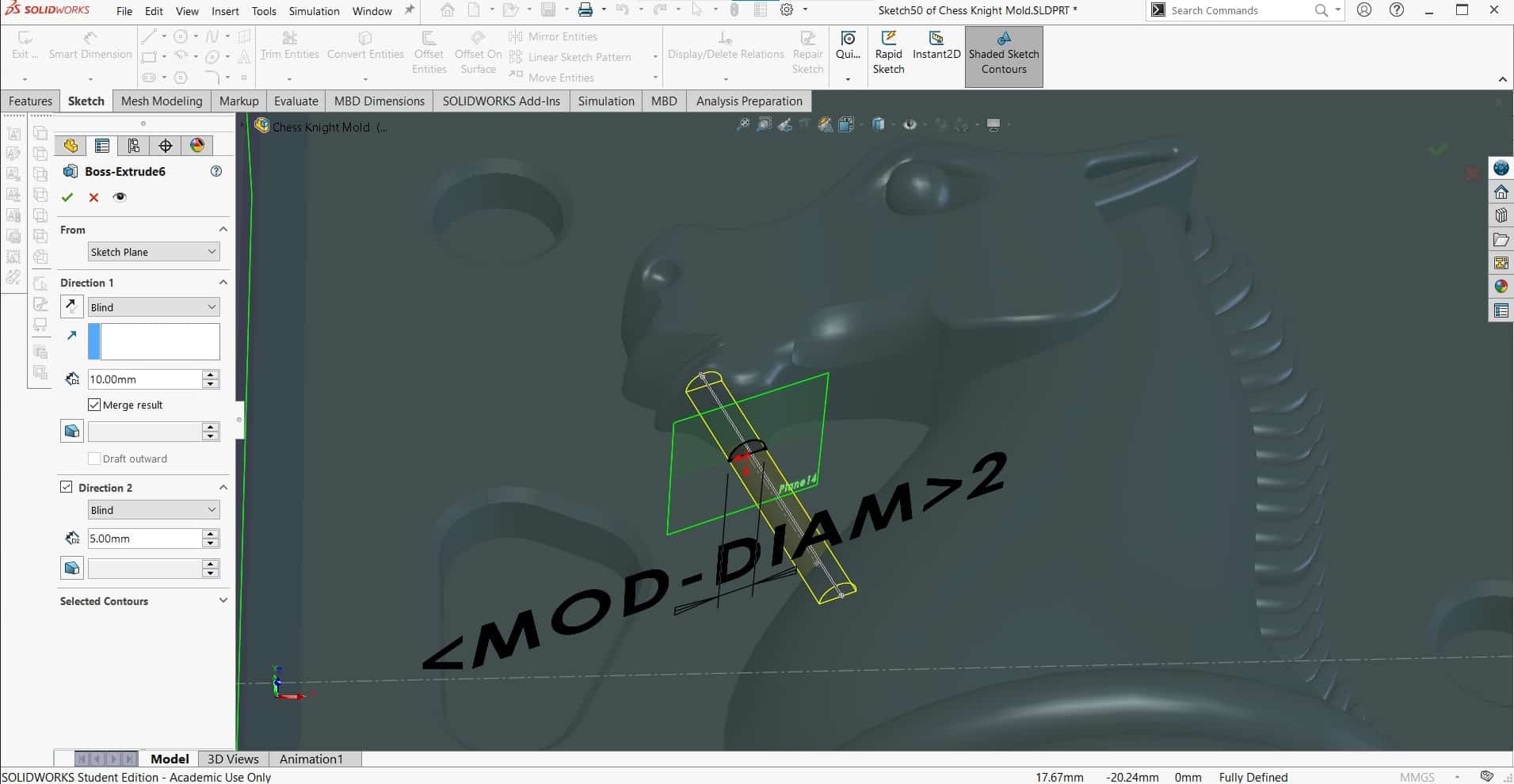
And then extruded half of a 2 mm channel where I wanted it.
More Mirroring
Of course adding the feature to the other side as well.
Sprues
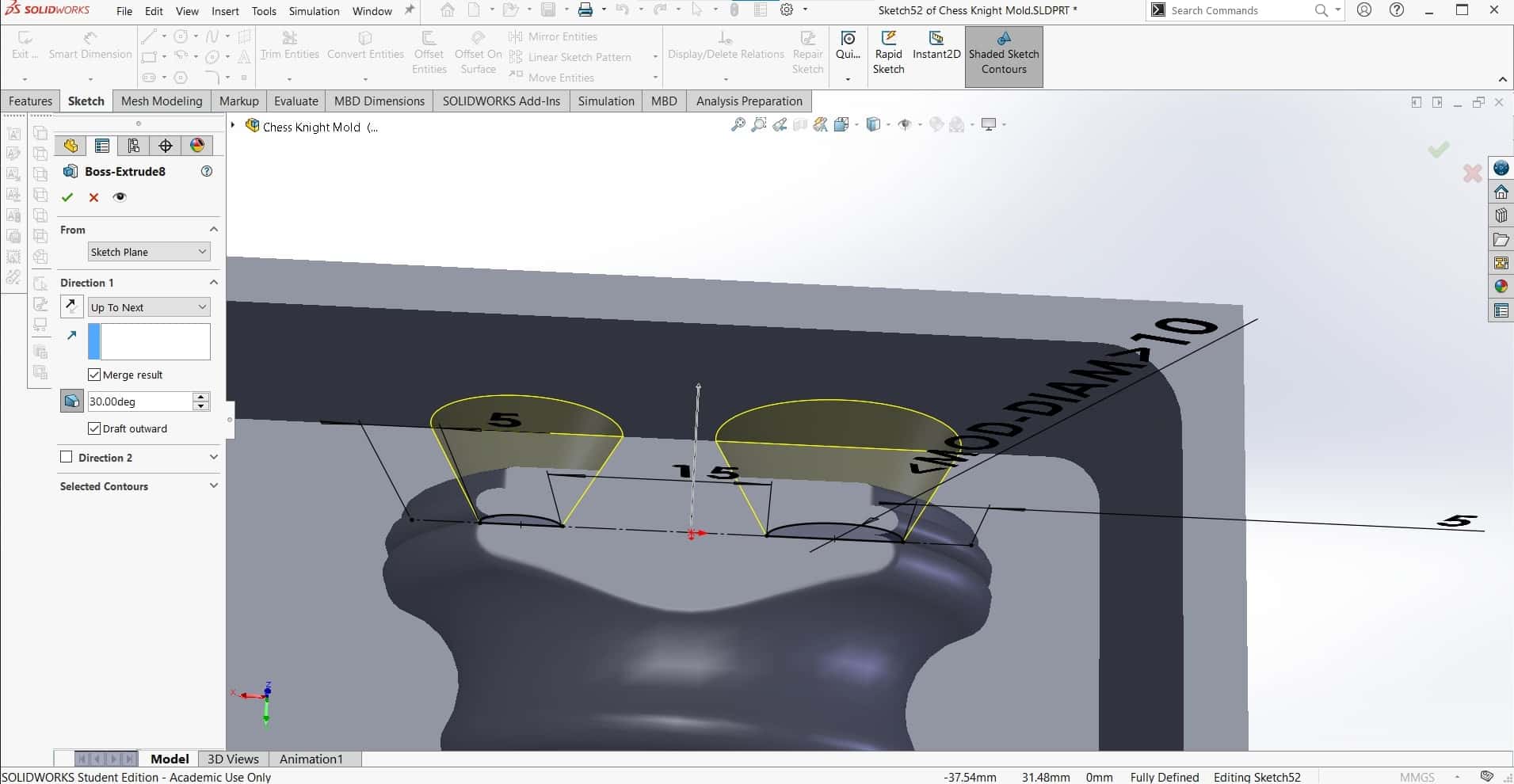
Finally, I added some sprues to the mold. The big one is for adding the resin and the smaller one is for allowing trapped air to escape as the mold gets filled up. I gave them both a funnel-shape.
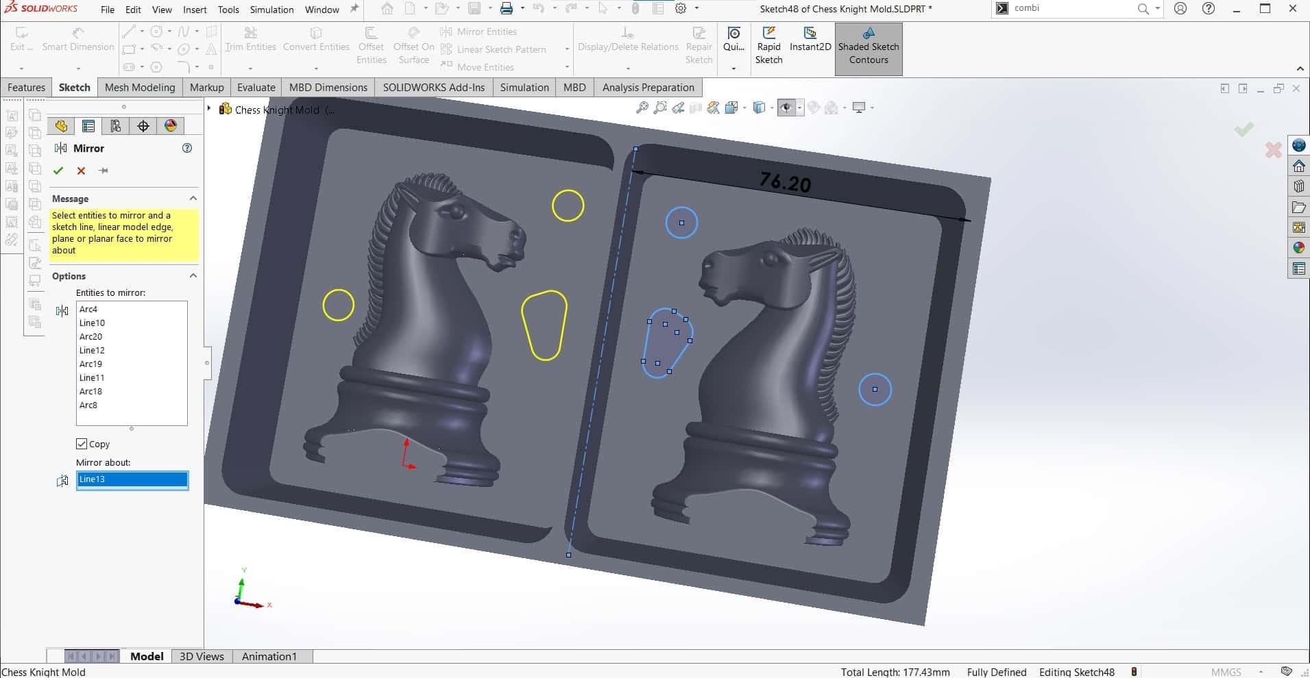
Even More Mirroring
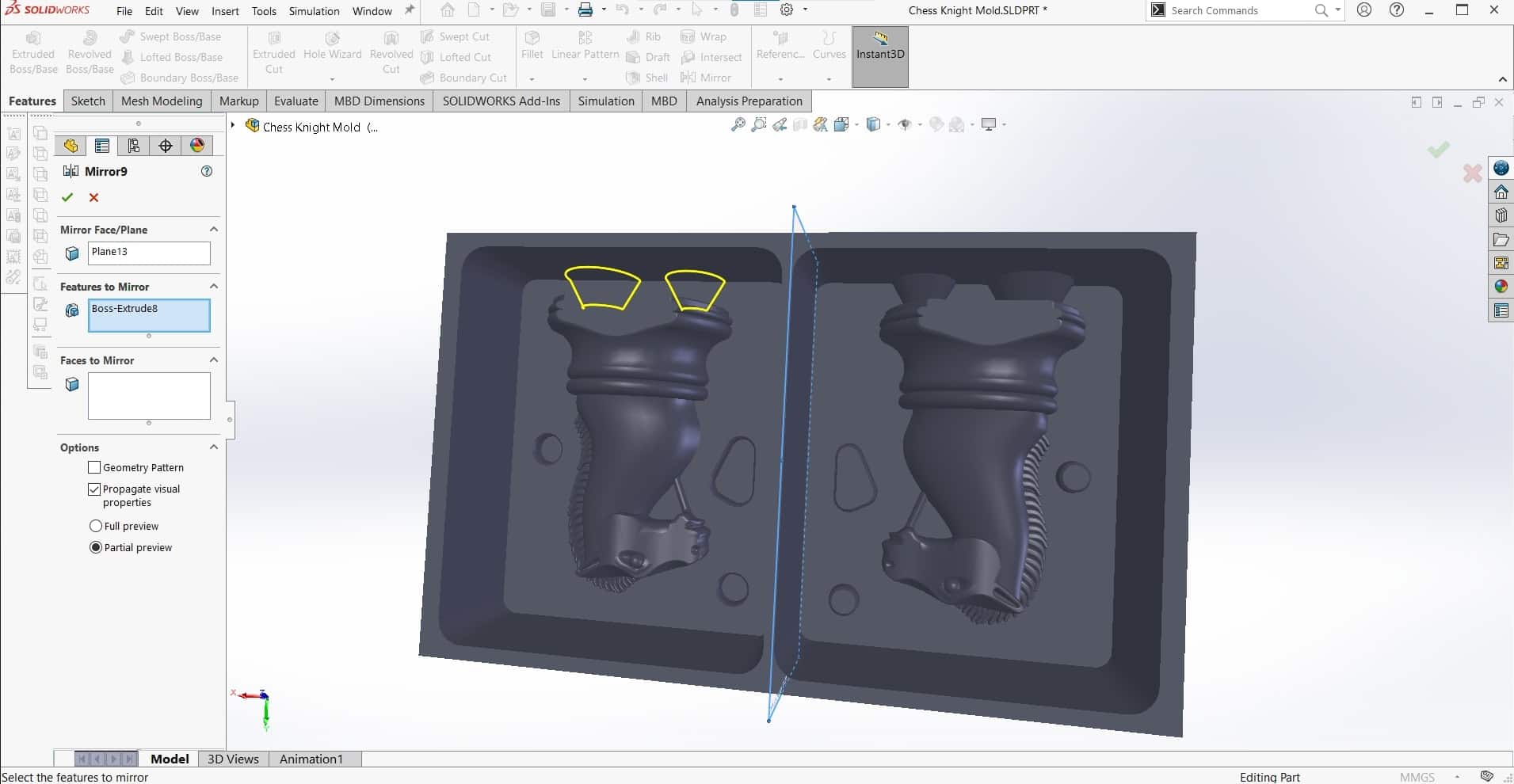
And I didn't want the other half of the mold to feel left out, so I mirrored the new features once more.
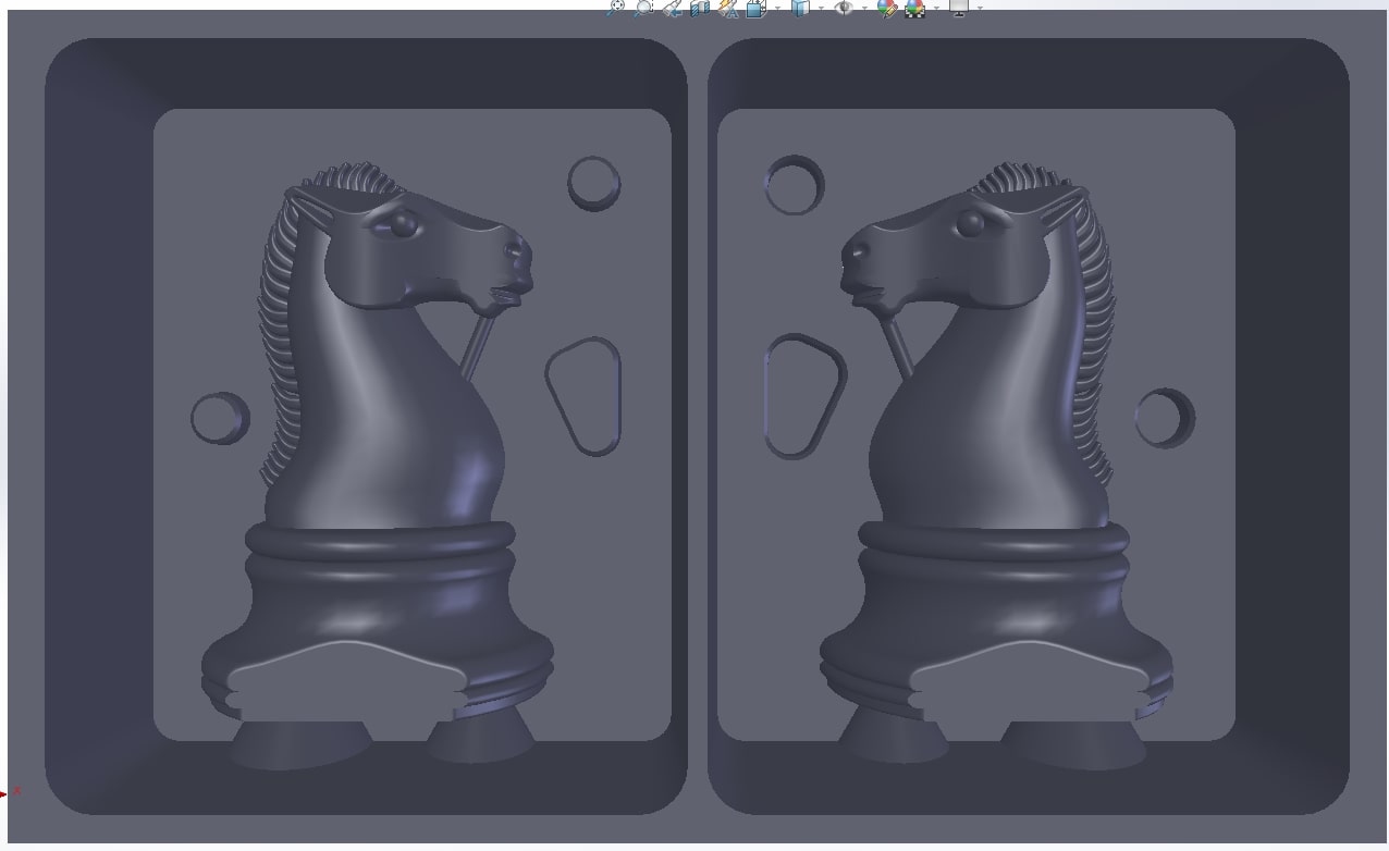
Done!
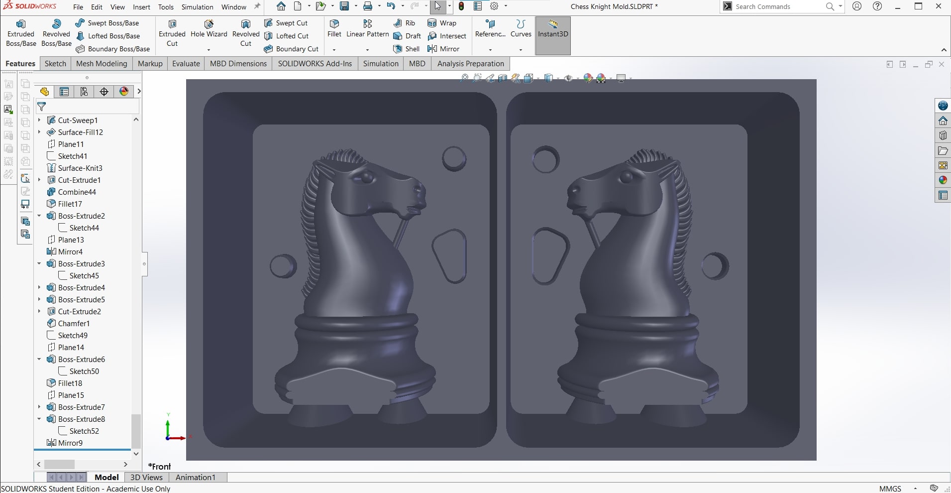
The model of the mold was now complete and I was ready to start building the CAM.
Creating the CAM
Fusion 360
I opened up the part in Fusion 360, once again very happy about the fact that I can so easily upload SolidWorks parts to Fusion without wasting time and energy on file conversions.
New Setup
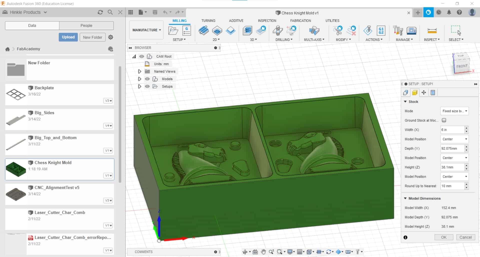
To begin the CAM, I went to the Manufacture tab and made a New Setup. I set the block to the dimensions from the box of wax and I put my origin on the top of the block on the lower left corner.
Pocket Cut
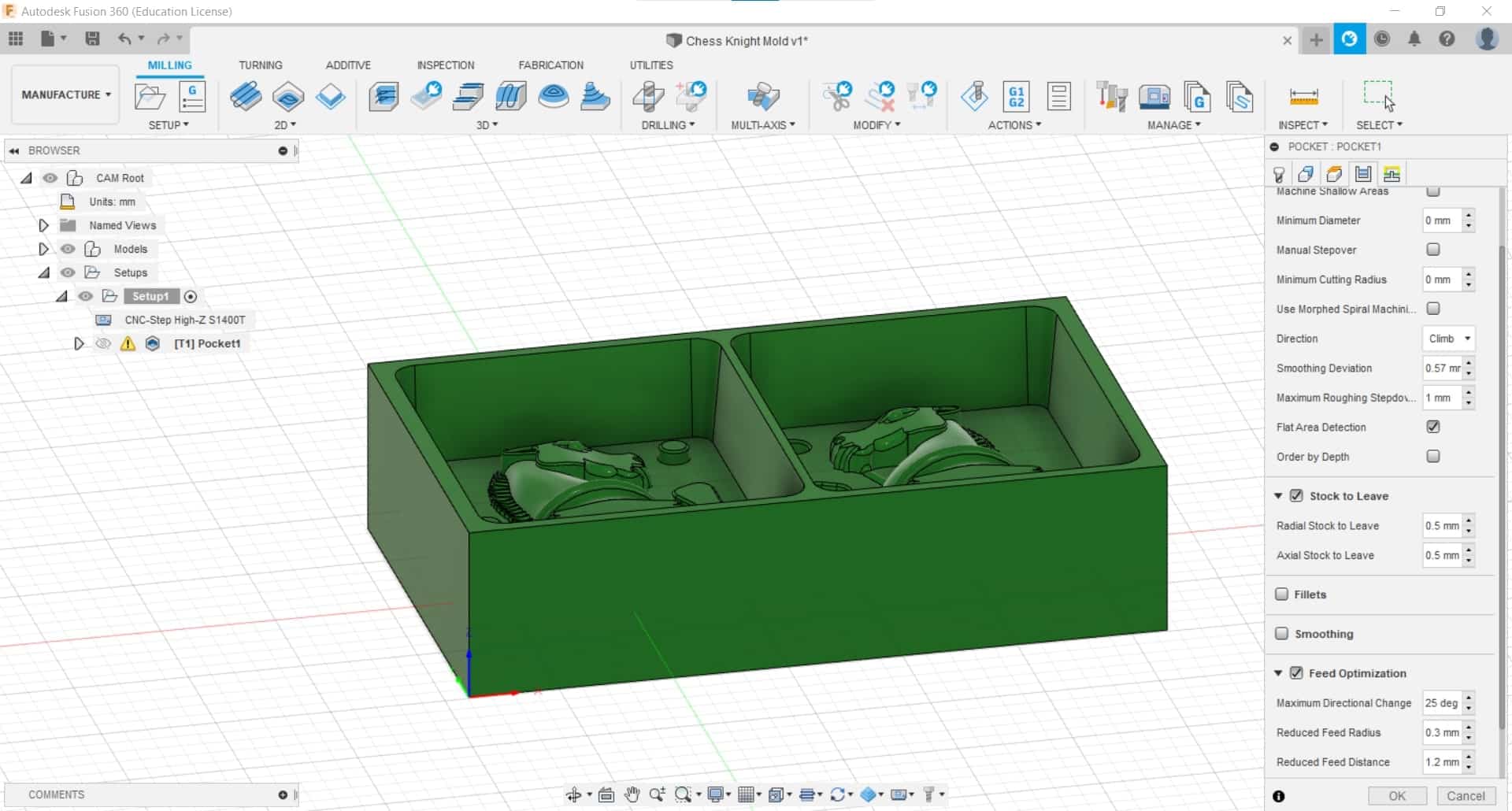
Next it was time to make some roughing passes. My general strategy was to do most of the roughing with a 6 mm flat end mill, so that's where I started. I clicked on Pocket in the 3D menu. I went with a 1 mm stepdown and 0.5 mm stock to leave in the axial direction. I also did a bit of trial and error with detecting the flat areas and optimizing the feed so it would slow down a bit when it changed directions.
Warnings
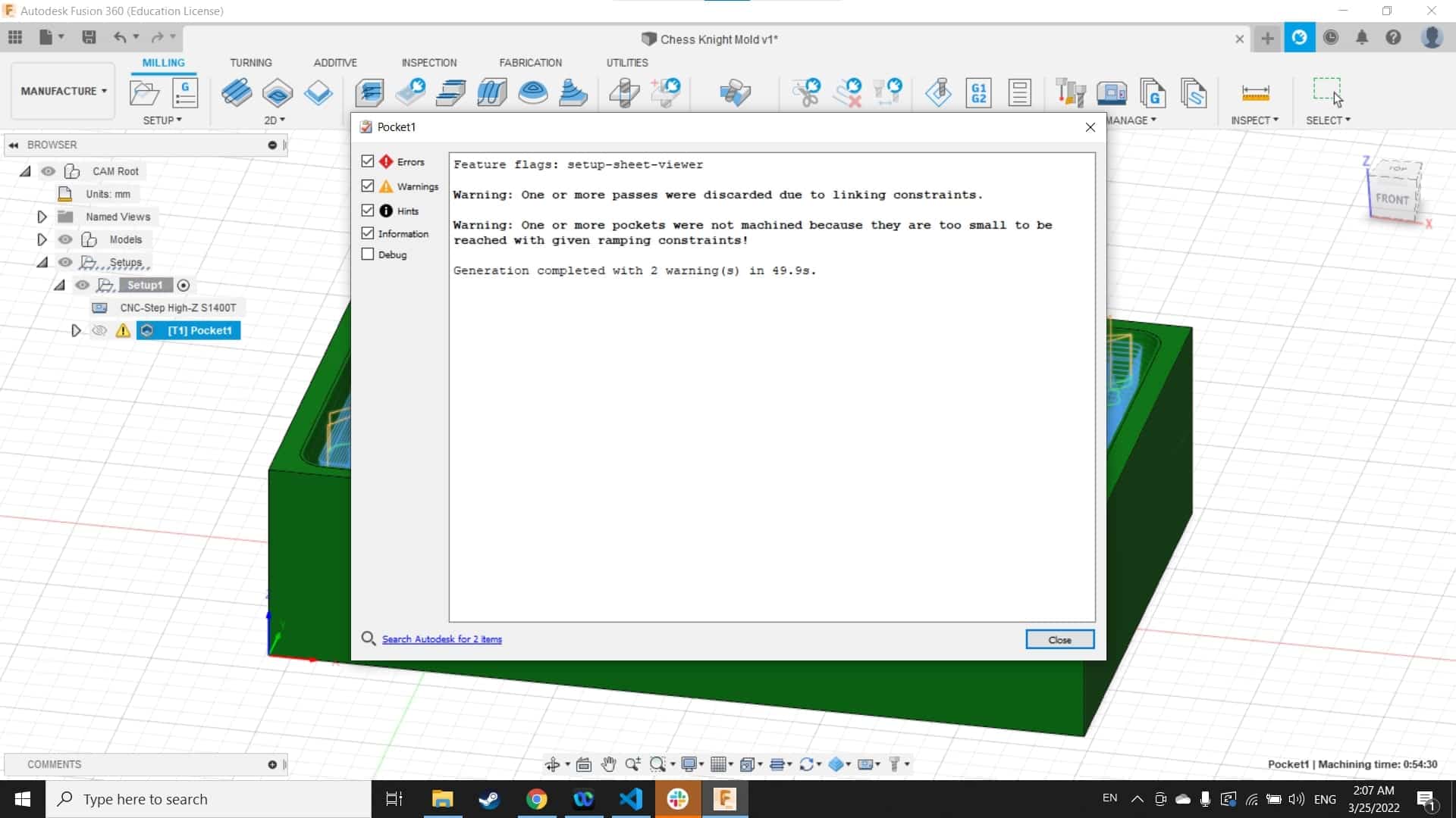
The operation generated two warnings I had not seen before, but they both seemed fairly reasonable considering the fact that the tool couldn't fit into the deepest pockets. This is just a roughing cut so reaching every nook and cranny was unnecessary. I appreciated the information giving me clues to what is going on behind the curtain so to speak.
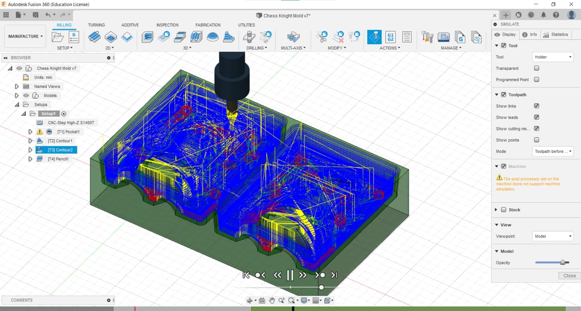
Simulation
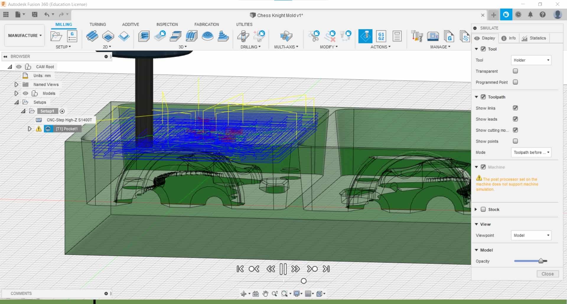
But of course I carefully watched the simulation to make sure I wasn't cutting anything I wanted to keep.
Tool Library
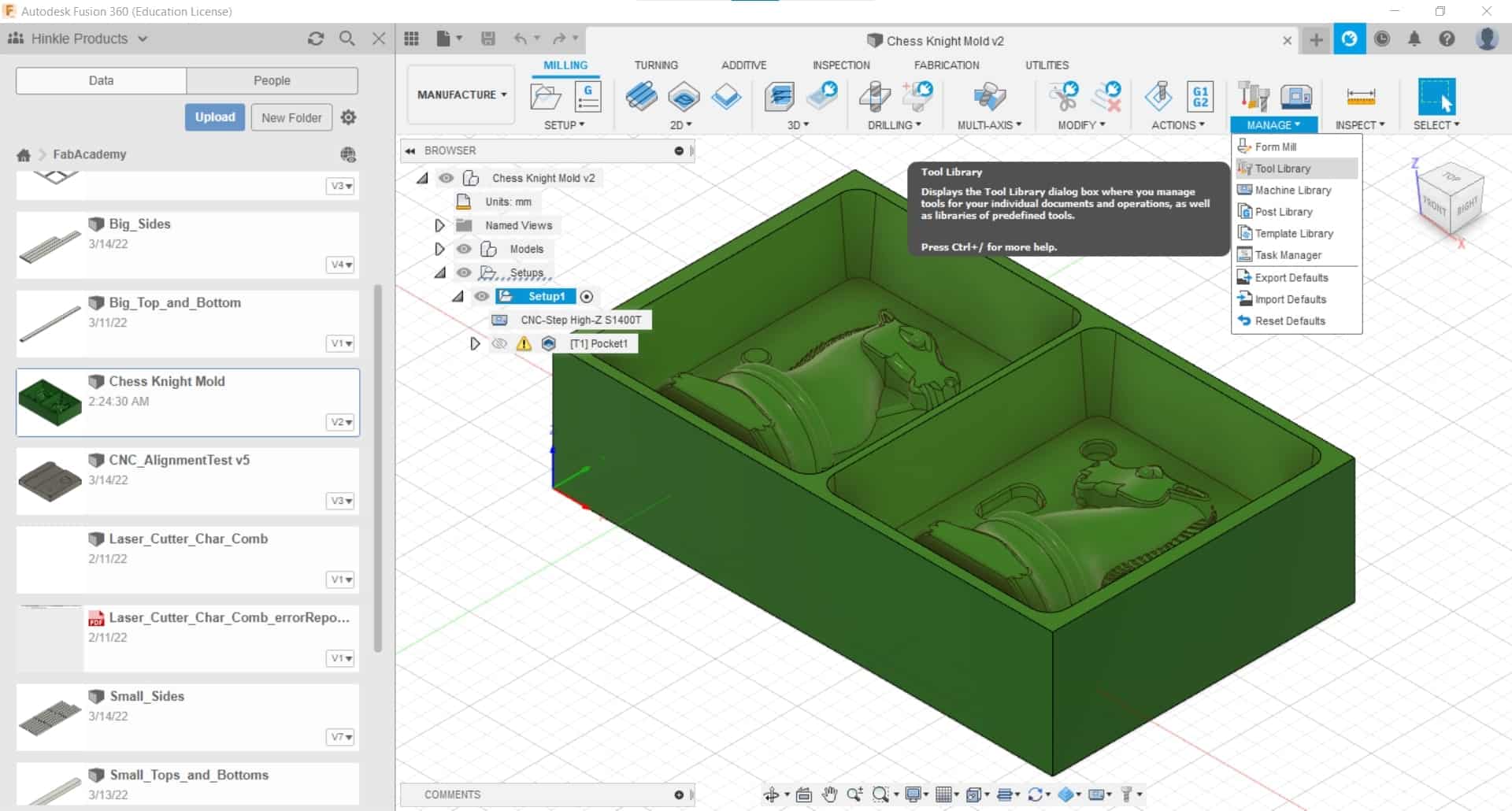
At this point, I could go no further without adding some tools to the library.
Measuring Tools
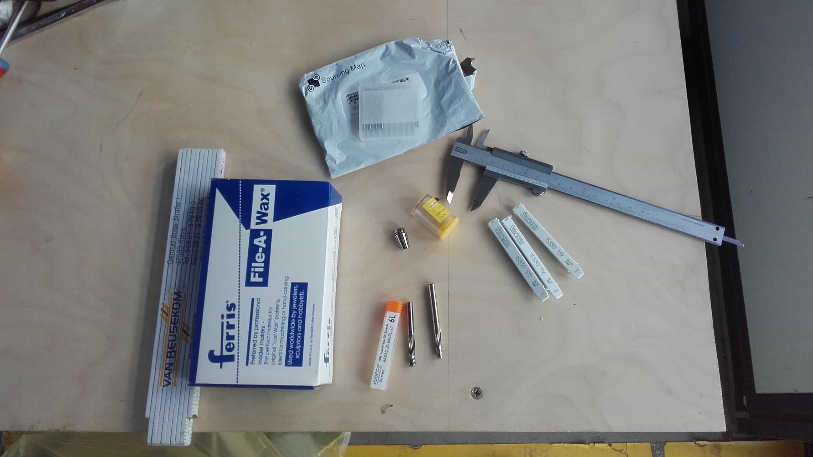
All we had in there were flat end mills >5 mm and I wanted to add some ball nose end mills and some smaller tools, so I got to work measuring and looking up vendors and recommended feeds and speeds for cutting wax.
Flat End Mills
I added 0.8, 1, and 2 mm flat end mills
Ball Nose End Mills
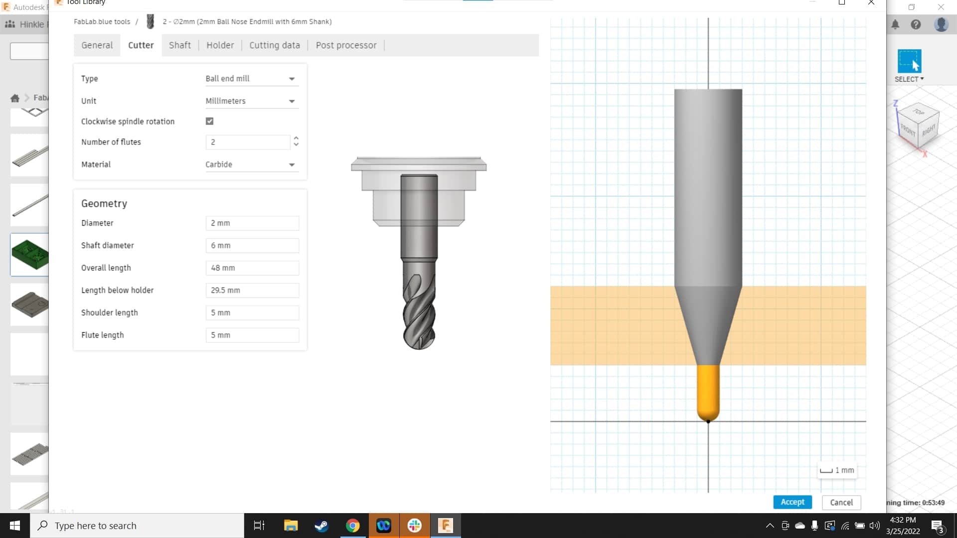
as well as 2, 4 and 6 mm ball nose end mills
Holder
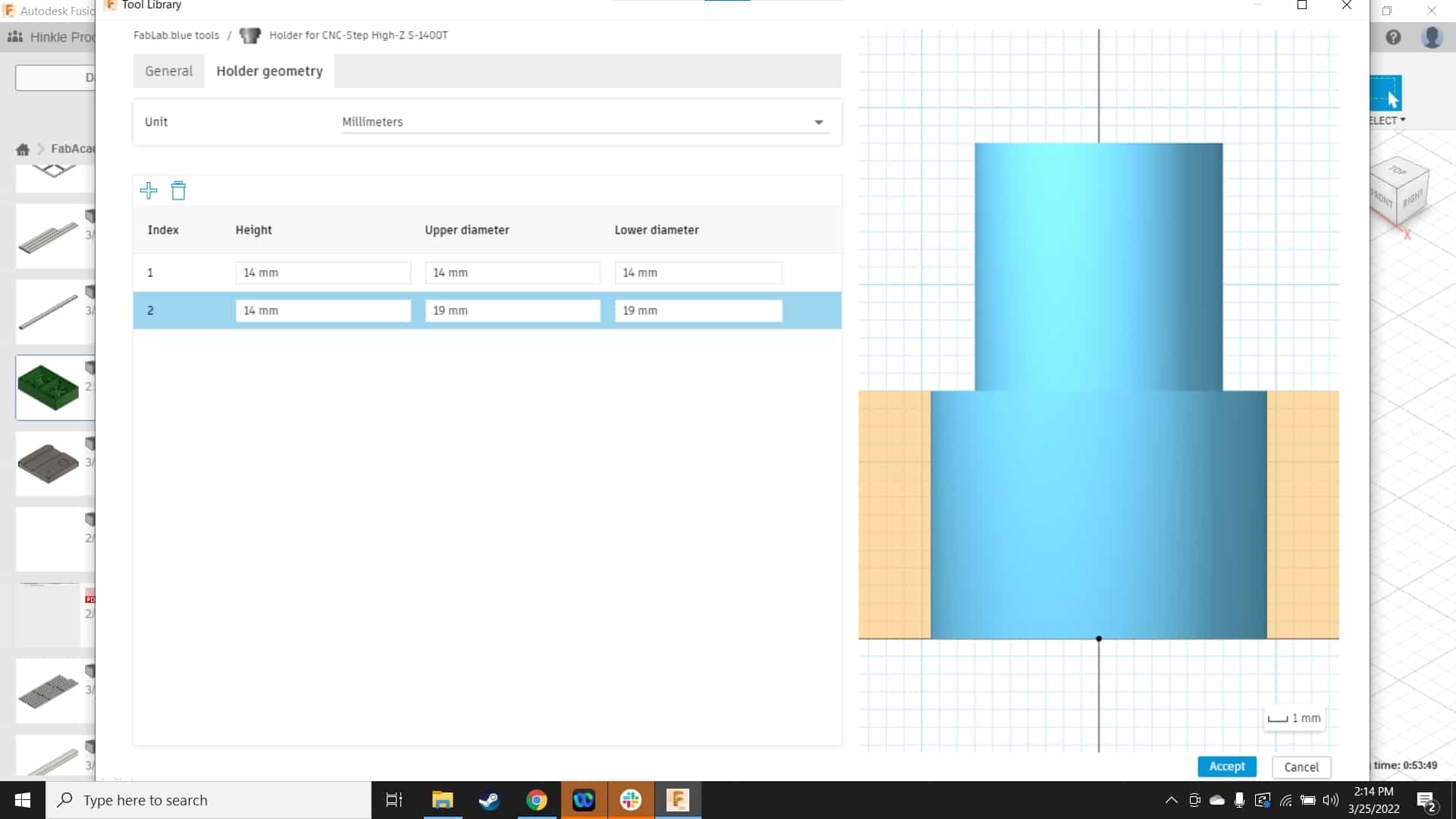
I also measured and modeled our holder and added that to the library as well.
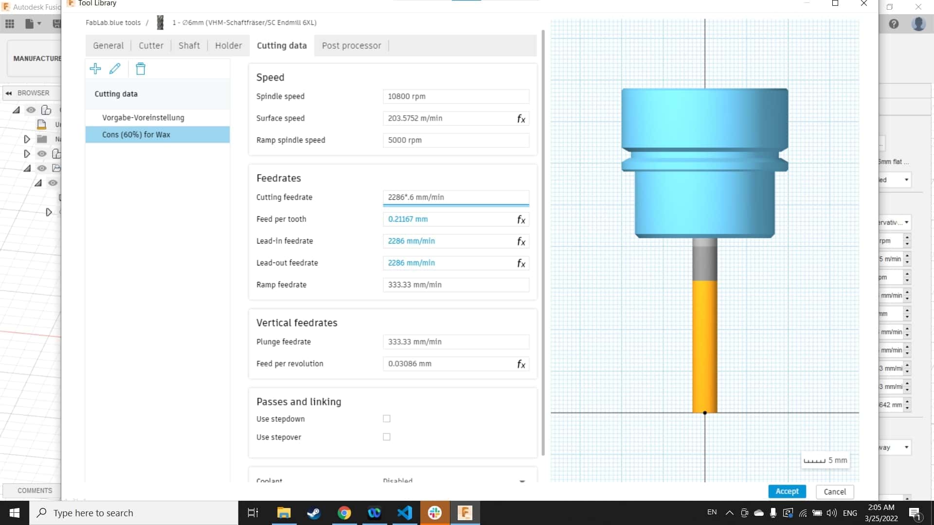
Asking the Experts
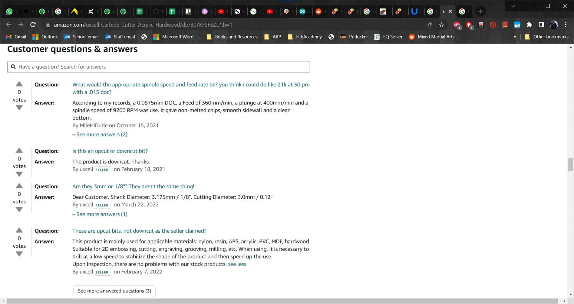
For some of the tools, I had a difficult time finding recommended feeds and speeds from the manufacturers, but fortunately, I found this handy chart with information for all kinds of tools and stock materials. I used it for all the tools I added to the library creating a wax-cutting configuration for each.
Second Roughing Pass
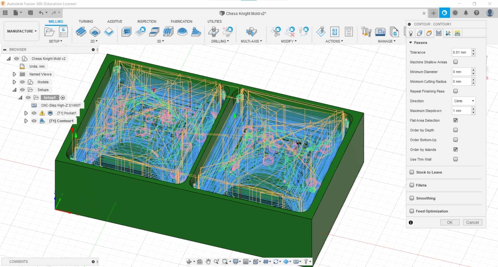
Now that I had the tools I would need, I set up a second roughing cut, this time I went with a 3D Contour Cut using a 6 mm ball nose tool. I chose a 1 mm stepdown and a 1.2 mm step-over, and I used 0.3 mm Stock to Leave in the radial direction.
Simulate
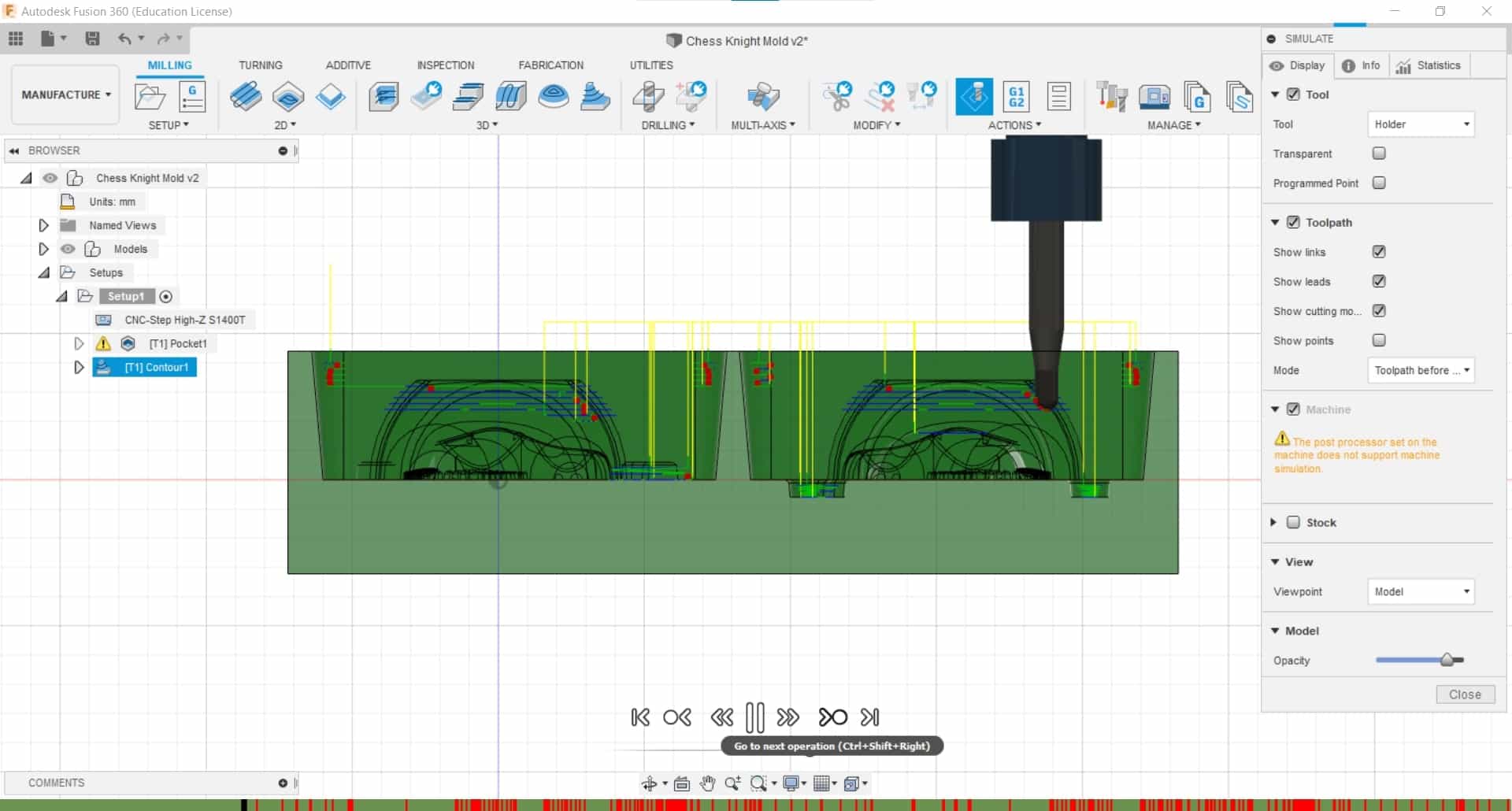
And then I simulated the new operation to make sure everything would go according to plan. This is where I realized that I forgot to turn on Rest Machining, so I popped back into the parameter menu and added it.
More Operations
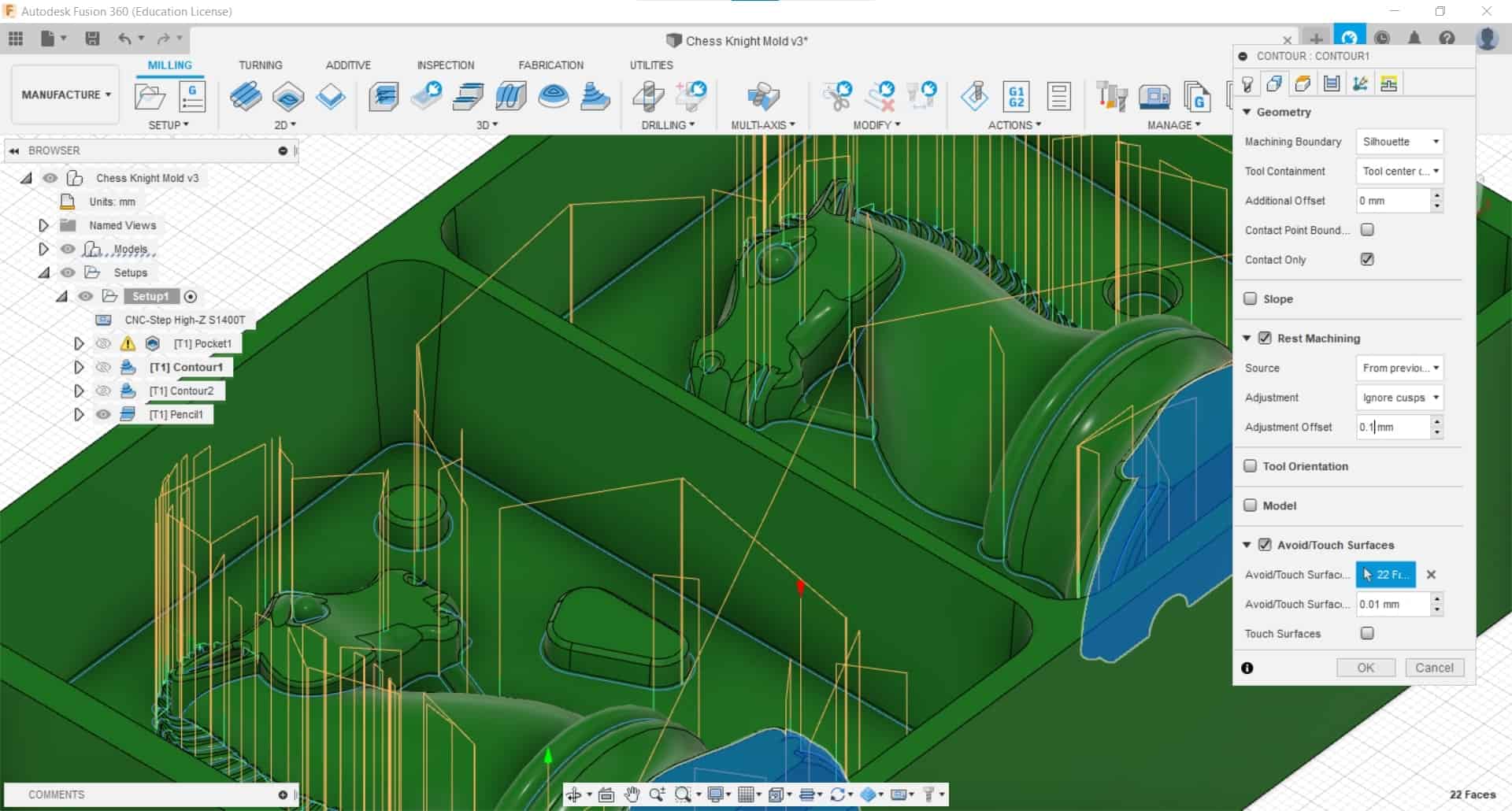
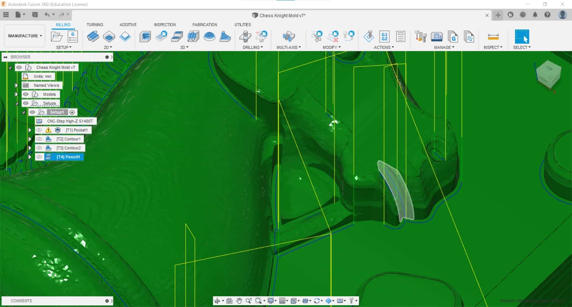
I also added two finishing passes - another Contour Cut with a 2 mm ball nose end mill, 0.1 mm stepdown, and 0.25 mm stepover; and a Pencil Cut with a 0.8 mm flat end mill to make sure the excess material around the outline was adequately removed.
Multi-Axis Tilting
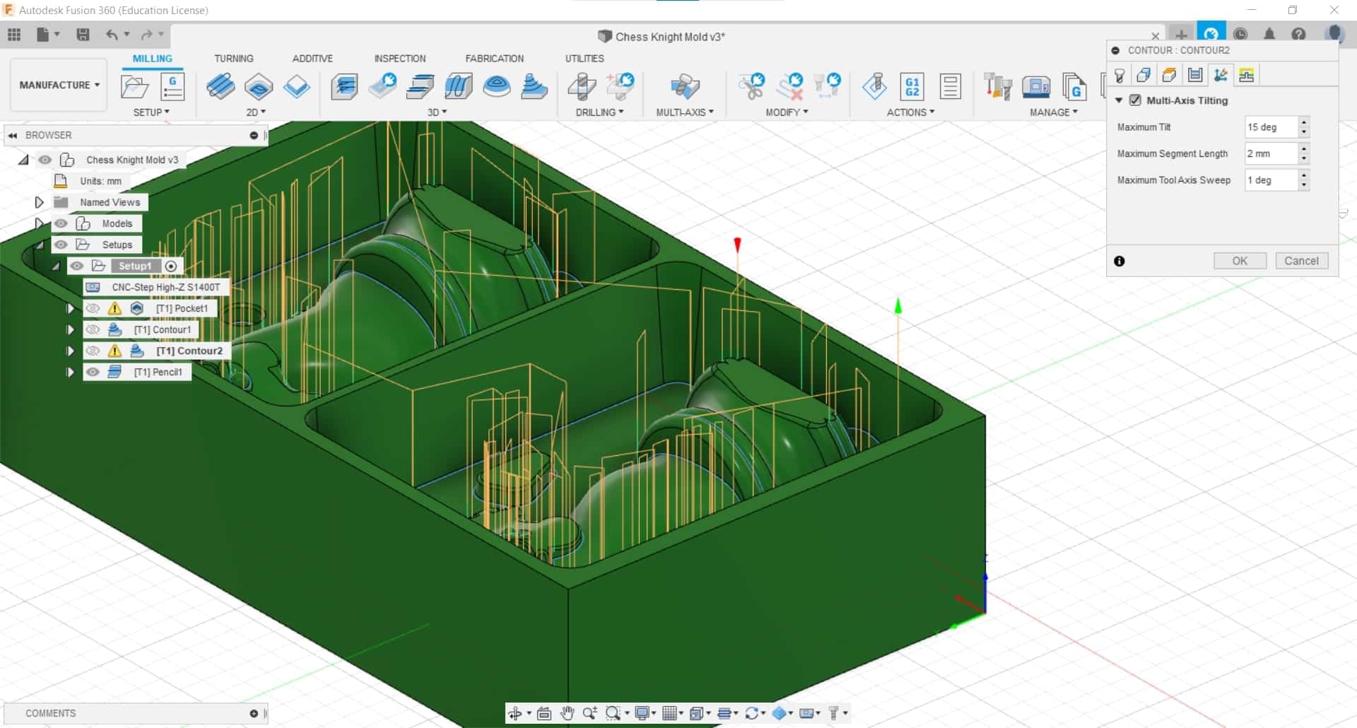
In the second Contour Cut, I experimented with using the Multi-Axis Tilting option, but the operation took almost two hours to generate...
Computer Says No
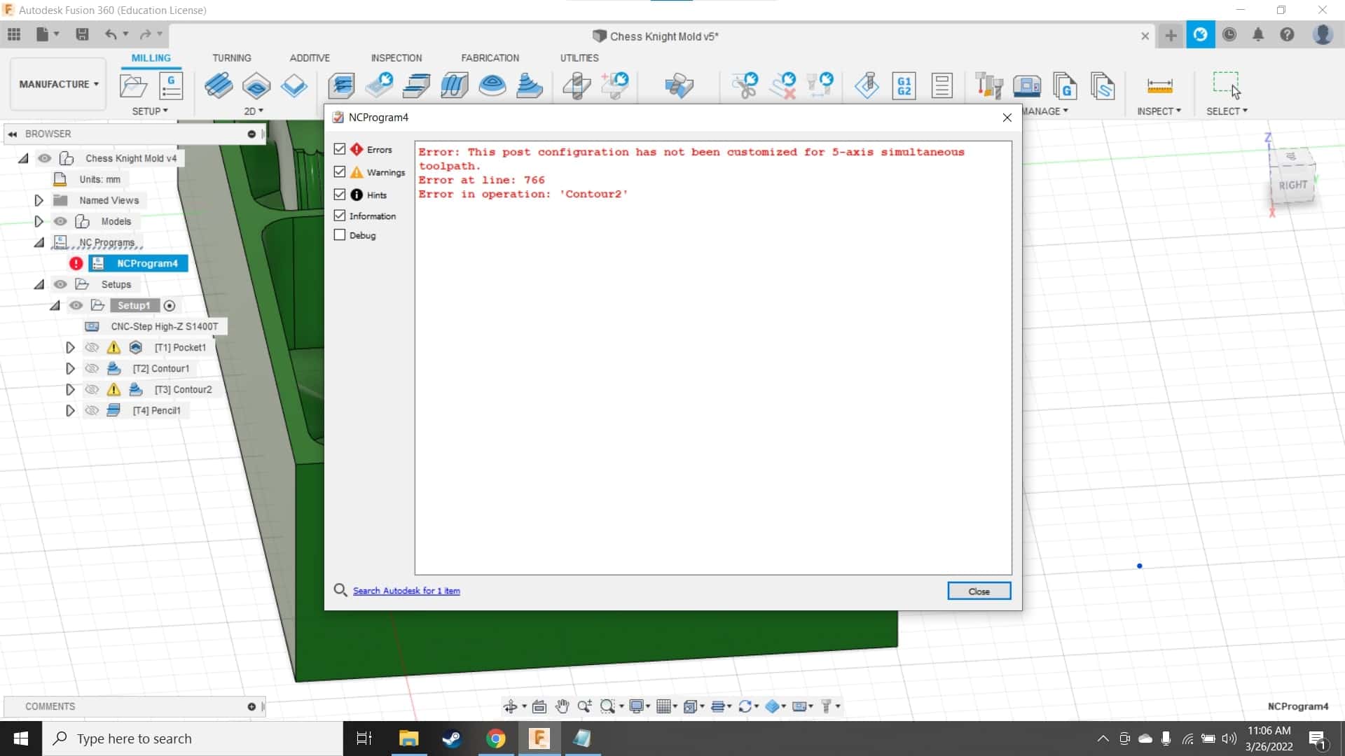
...and later when I went to generate the g-code, I found out that our machine can't even support this type of operation so I am not sure why it's even available to select.
False Advertisement
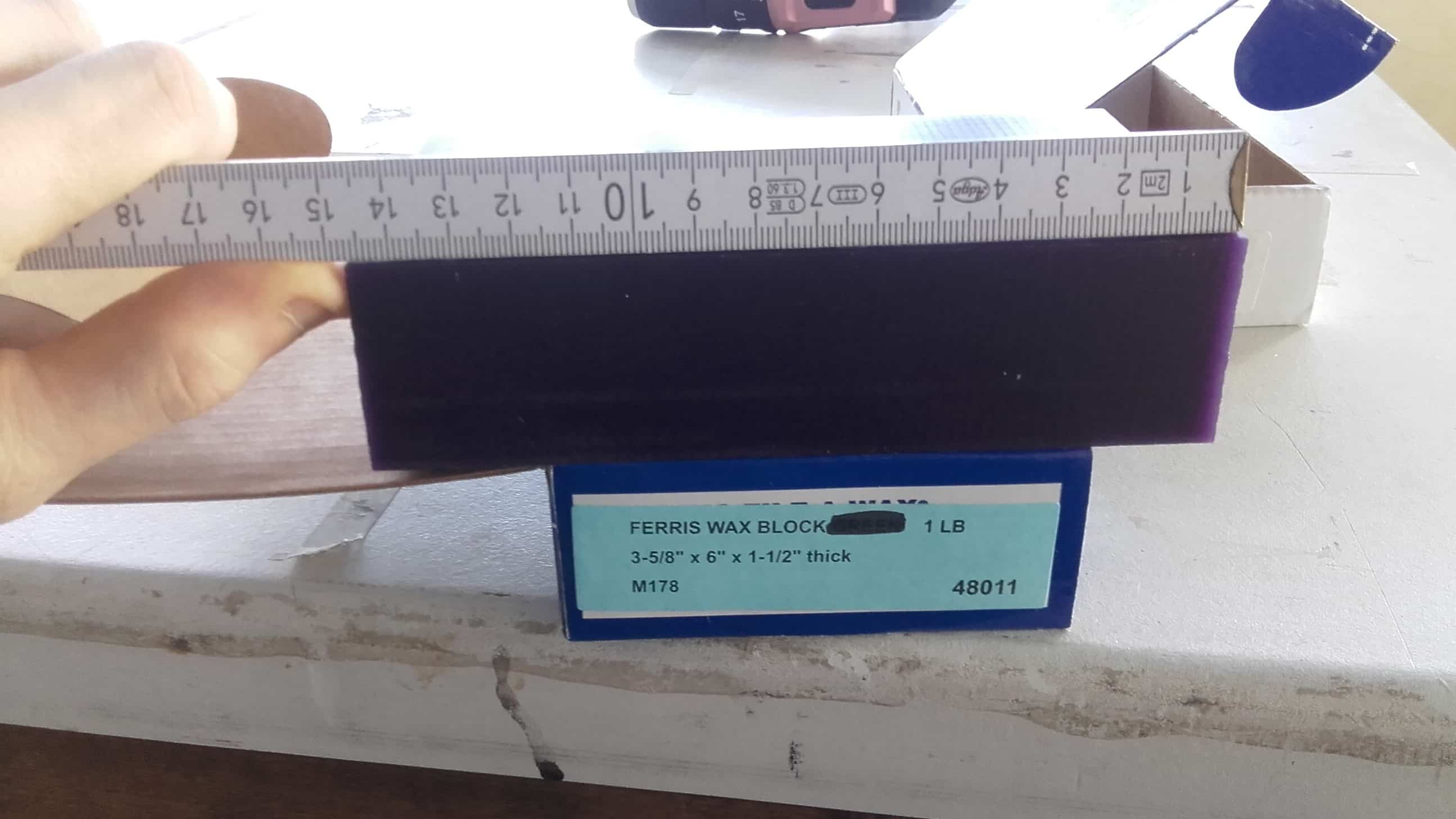
I finished the CAM and headed to the lab the next day to start milling. This was when I decided to measure the actual stock, instead of just looking at the dimensions on the box. And of course, the dimensions of the stock did not match the description. The block was 10 mm shorter in one axis and 5 mm shorter in another axis. So I had to head back into Fusion.
Solution
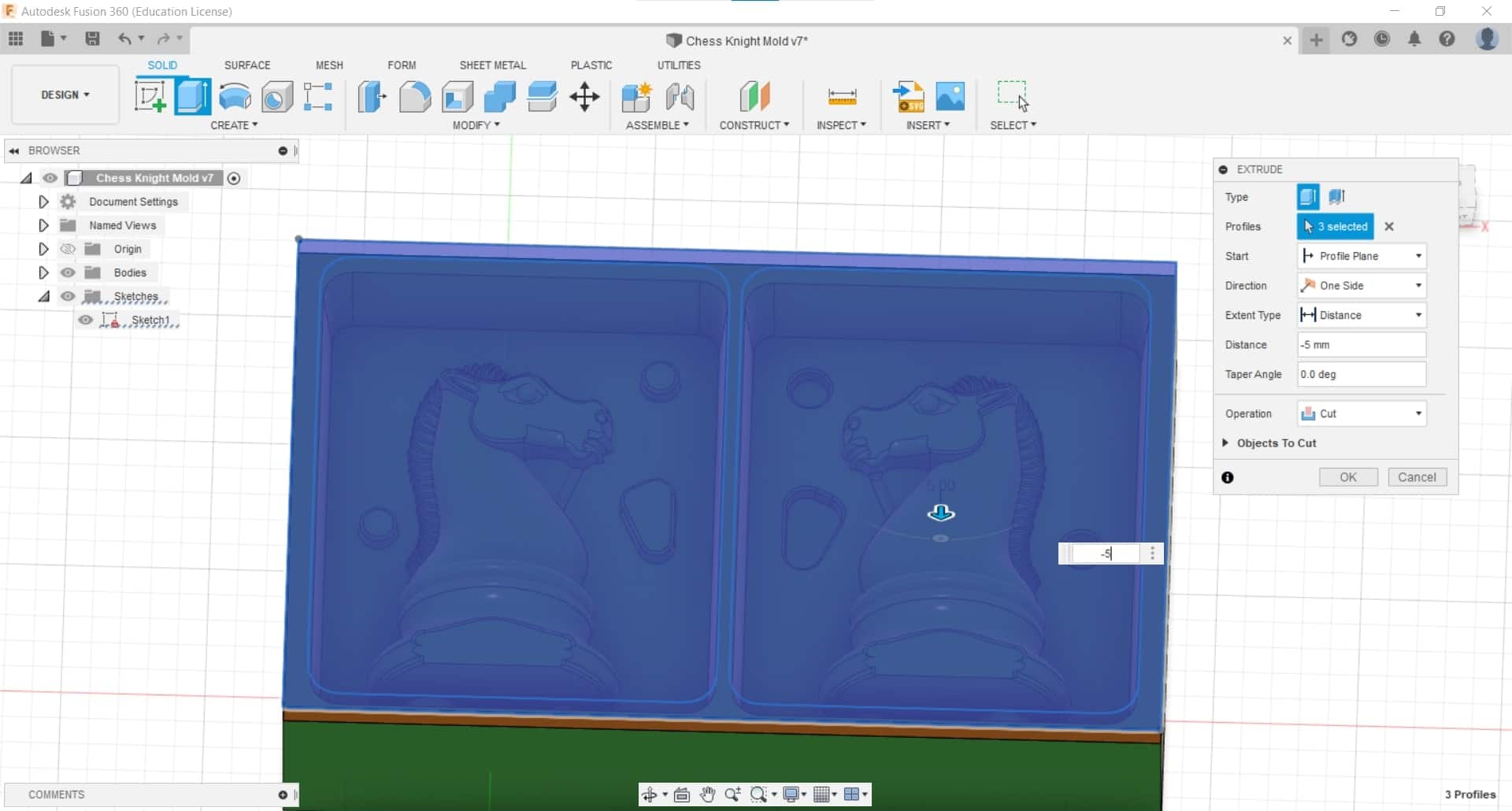
The walls of my mold were already thin so I had to change strategies. I decided to change my draft angle to 5° and then to remove all the material above the top of my knight. This would mean I would have to build a small box around my mold to meet the 1.3 cm minimum required thickness for the silicone, but at least it would be millable.
Extruding Away the Excess
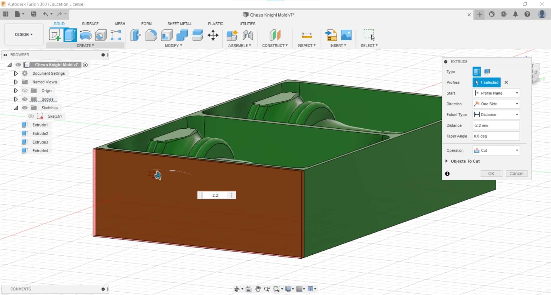
Once I took down the face, I shortened the ends as needed to fit the actual dimensions of the wax.
Updating Setup
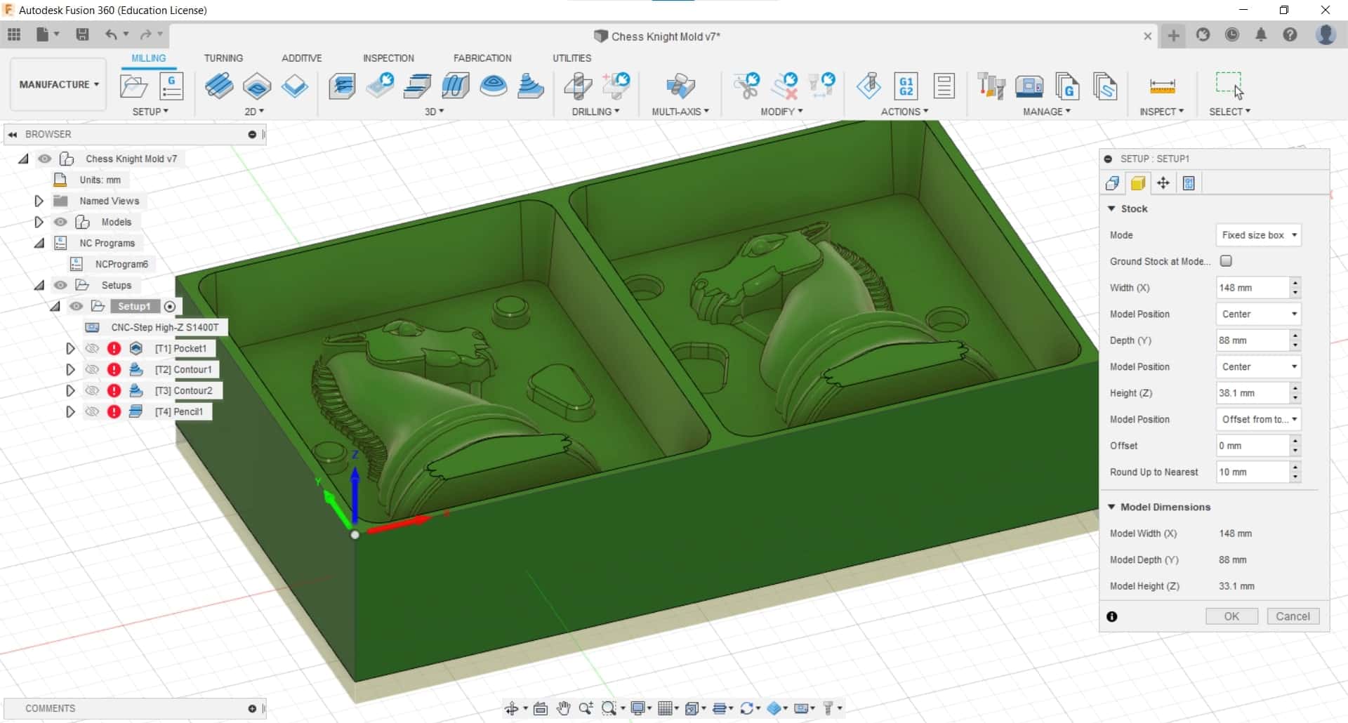
And then updated the Stock in the Setup with the new information as well.
Good Enough
I updated all the operations once more and, although it still clearly wasn't perfect (especially in this one frustrating area around the neck), any other operations I tried just resulted in empty tool paths so I thought this was the best I could do with my tool set. If I was planning to cast metal, I would have tried a little harder for perfection...but the materials I intend to cast with are soft and easy to clean up manually if necessary.
G-code
Then I simulated and simulated. I watched every second of every operation to make sure that the tool only went where I wanted it. Once satisfied, I generated the g-code using the Post Process tool from the Action Menu.
Double Checking G-code
Simulating
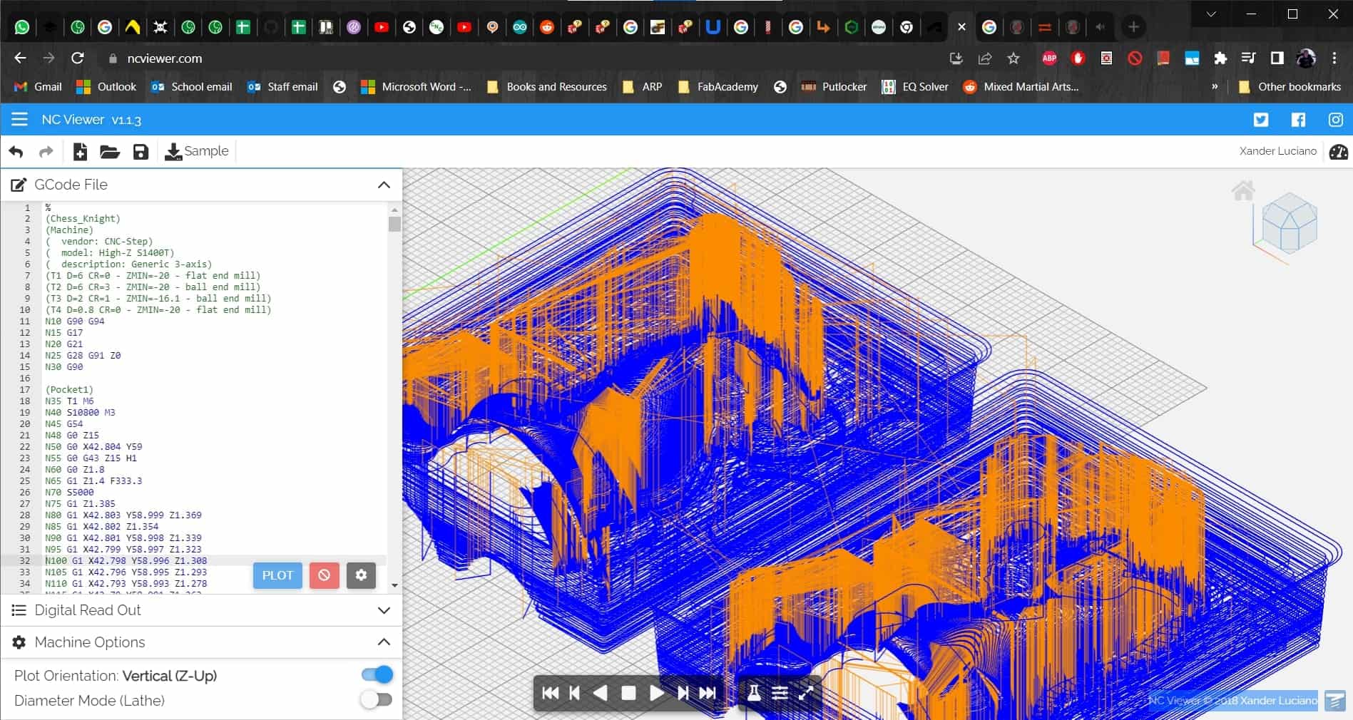
And then took it immediately over to NCViewer to simulate the results of the post processing. Once again, our machine is disconcertingly suicidal. It added commands to run the tool directly through the workpiece at the onset of each operation.
Translating and Replacing
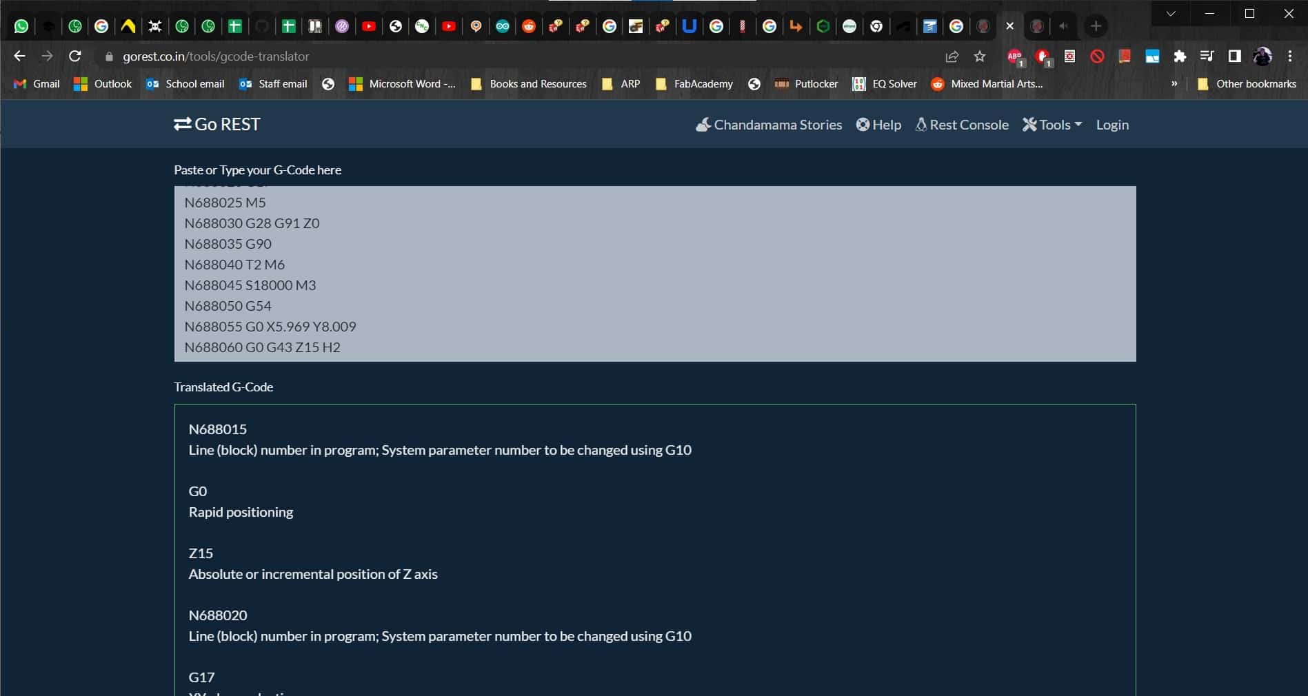
I removed the suicidal commands and added a few to ensure the spindle only traveled in x and y axes when the z axis was at a safe height. I also used the g-code translator to add a command for the machine to travel to the tool change position each time an operation ended and a tool change was required to go on cutting.
CNC Cutting the Wax
Milling the Origin
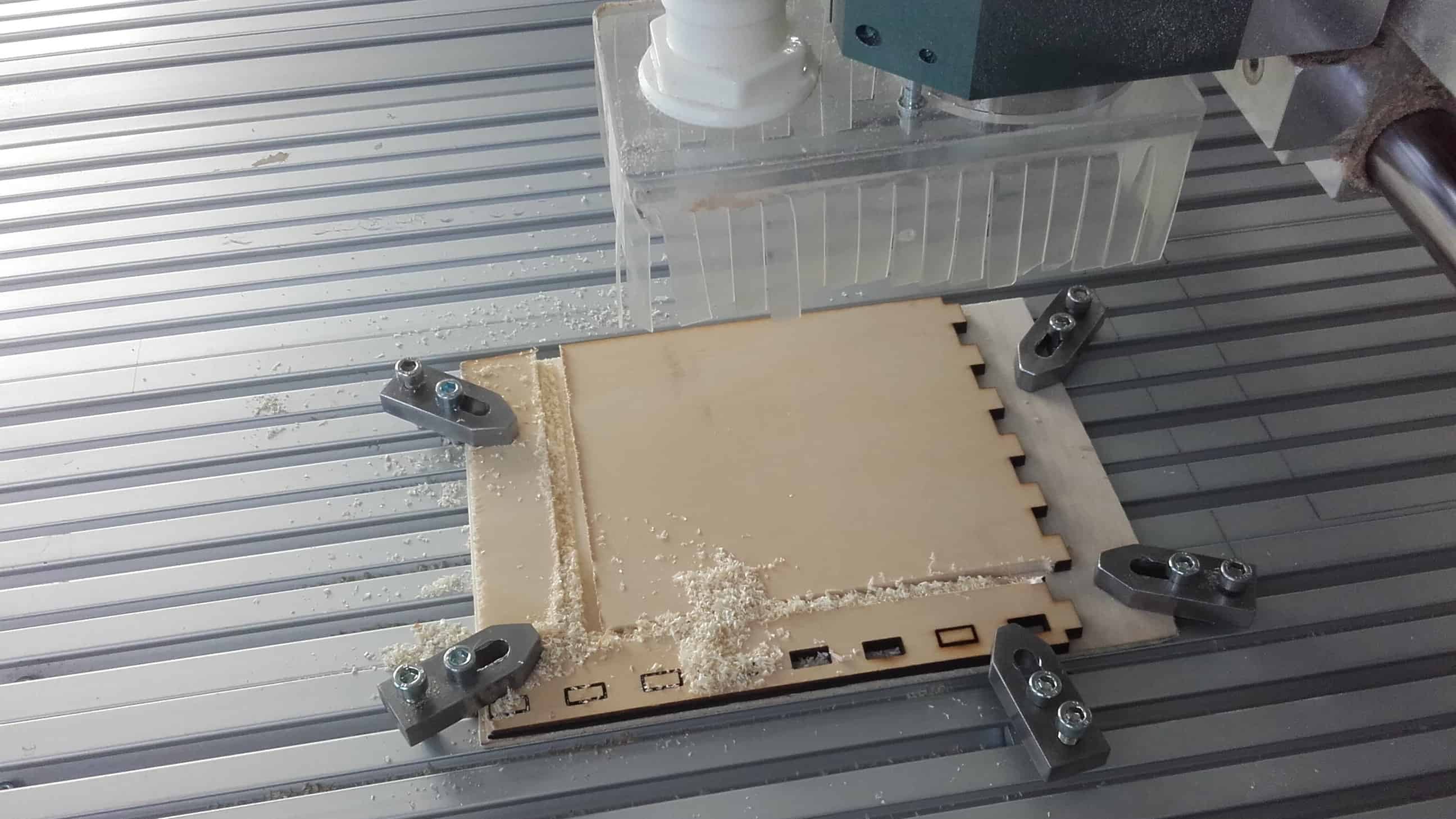
I started by finding a couple pieces of scrap to use as sacrificial material and carefully clamped them to the bed of the CNC machine. Since it worked out so well during my Something Big project, I decided to mill my origin again.
Cleaning and Adding Stock
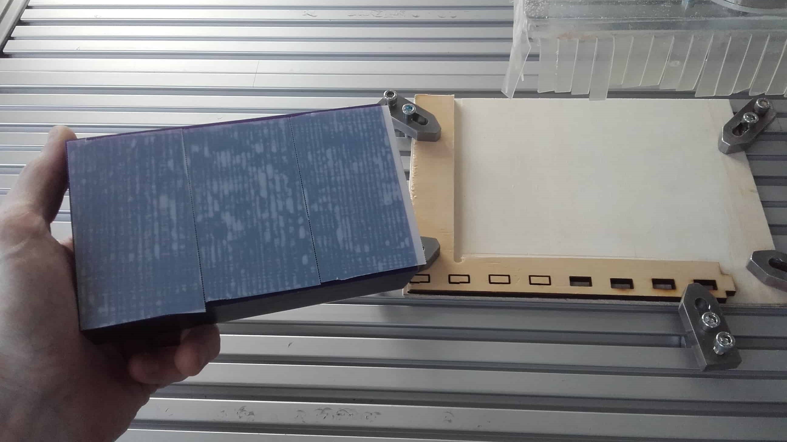
I carefully cleaned all of the sawdust and dirt out of the bed and emptied the shop vac before cutting. I doubt the wax chips will be clean enough to reuse, but I gave it my best effort. I used double sided tape to secure the wax stock to the sacrificial layer.
Preview Buffer Limit
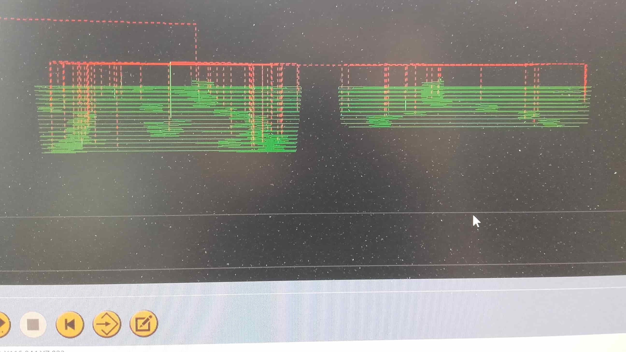
KineticNC gave me a scare since this is the first time I have run into its buffer limit on the preview window. I spent a half an hour trying to figure out where the rest of my tool paths went before realizing what was going on. I'm not a big fan of KineticNC.
Ready, Set, Go!
But once I figured out that all the g-code was in fact present and accounted for, I used the paper method to set my z-0, put my hand on the E-stop, pressed play and watched the action commence.
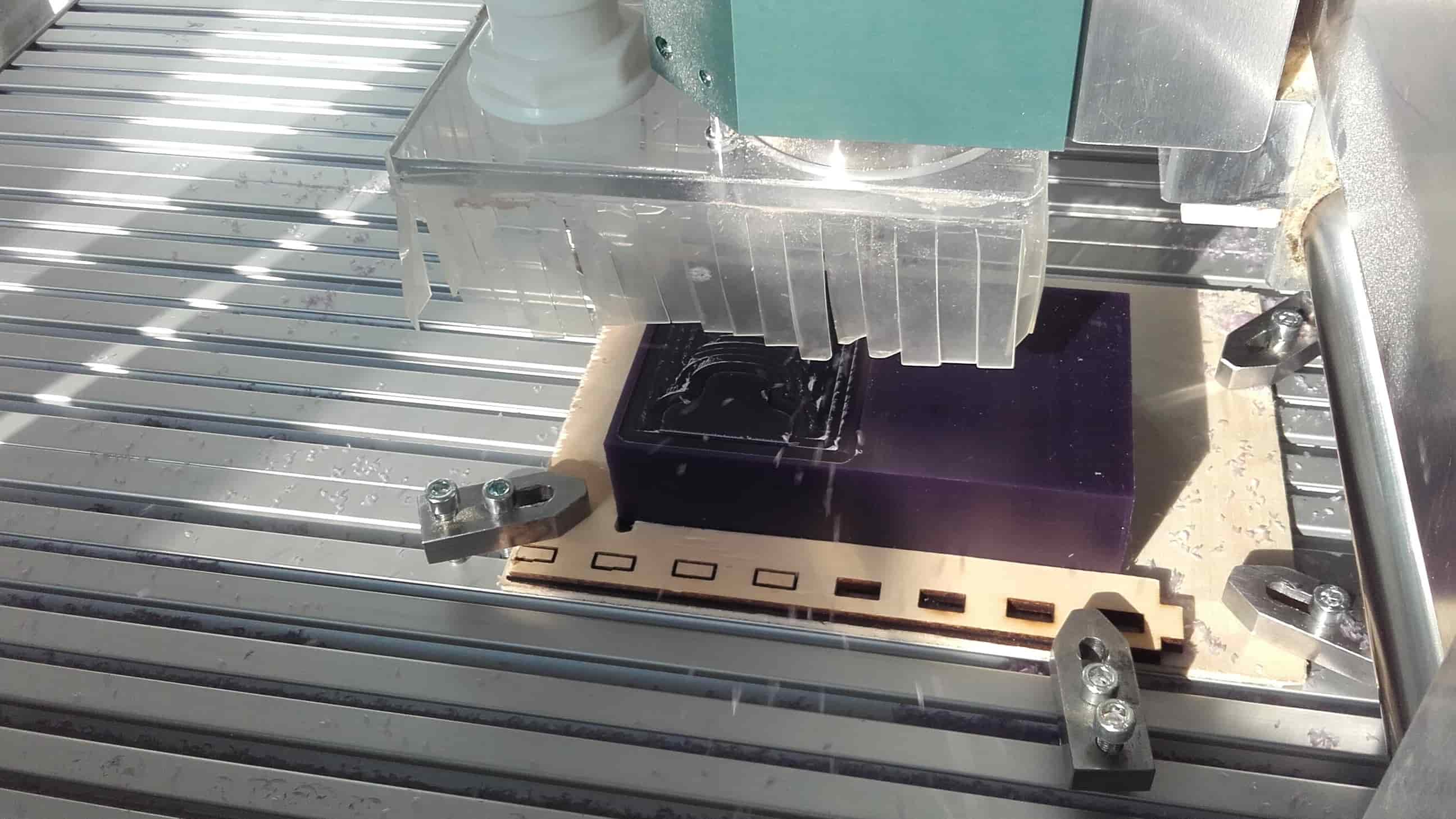
Roughing Cut
It was clear what I was making even after the first roughing cut.
Second Roughing Cut
And it was already looking pretty nice after the second roughing cut.
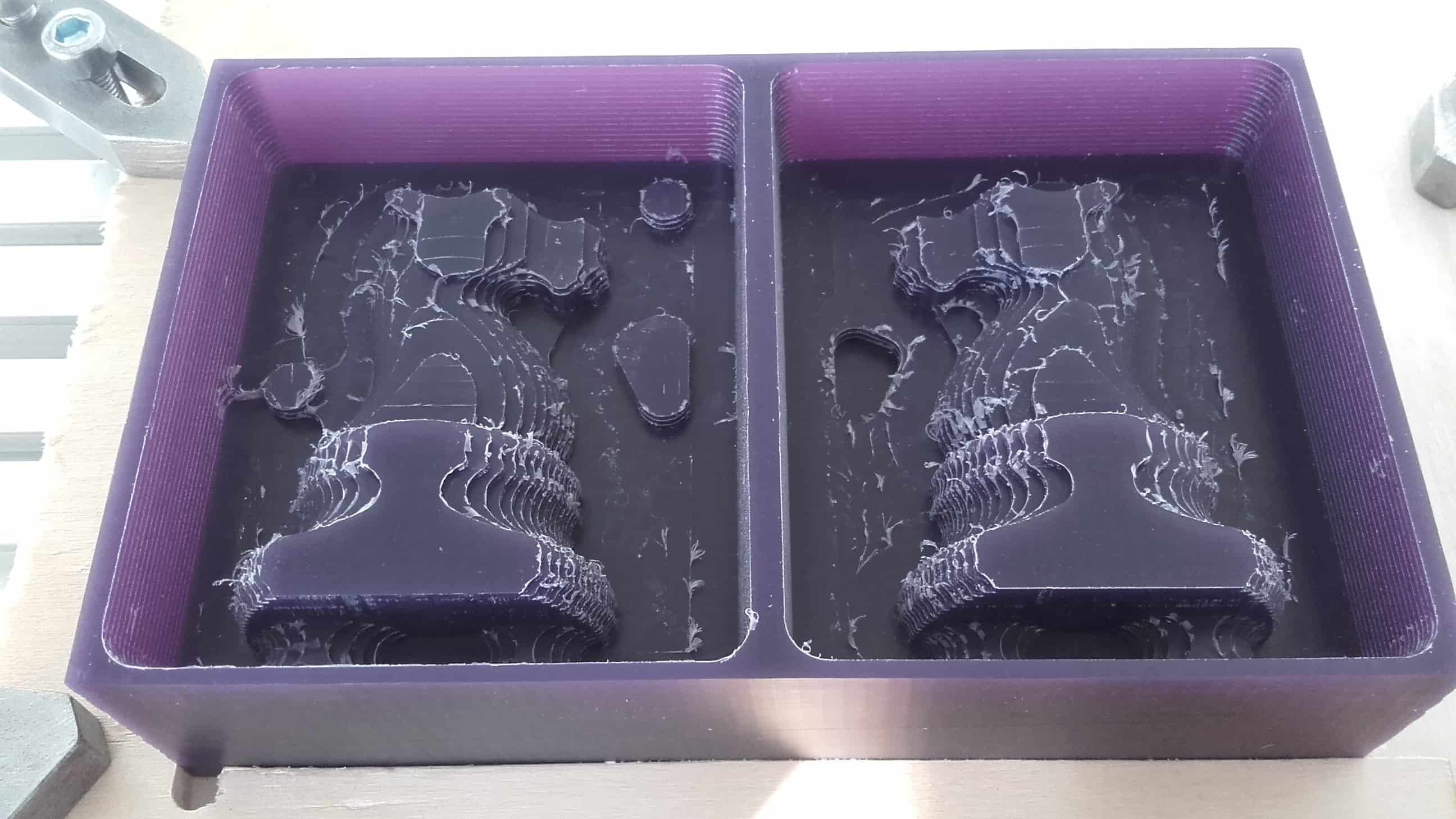
Finished
After the finishing passes, the part was looking really good.
Not Perfect
I still had the anticipated trouble areas near the neck and around the sprues...
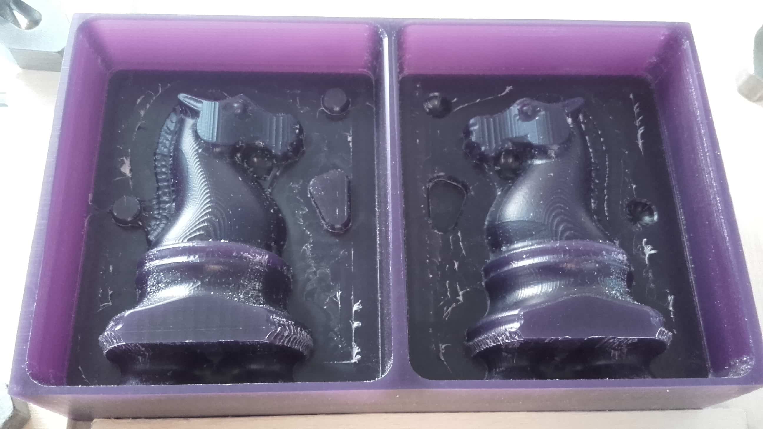
Cleaning Up the Mold
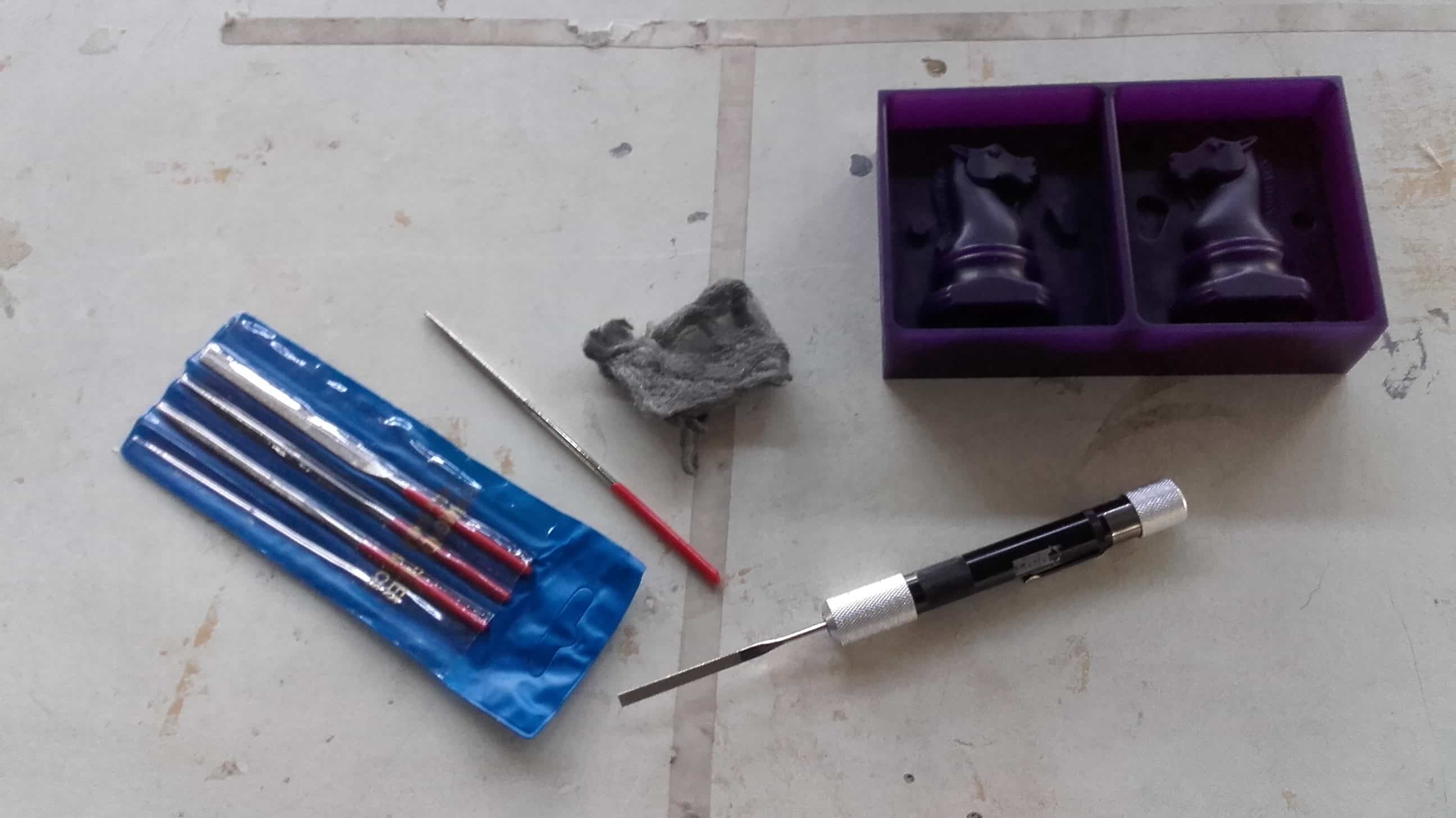
So I got to work with some small wax hand files and some steel wool.
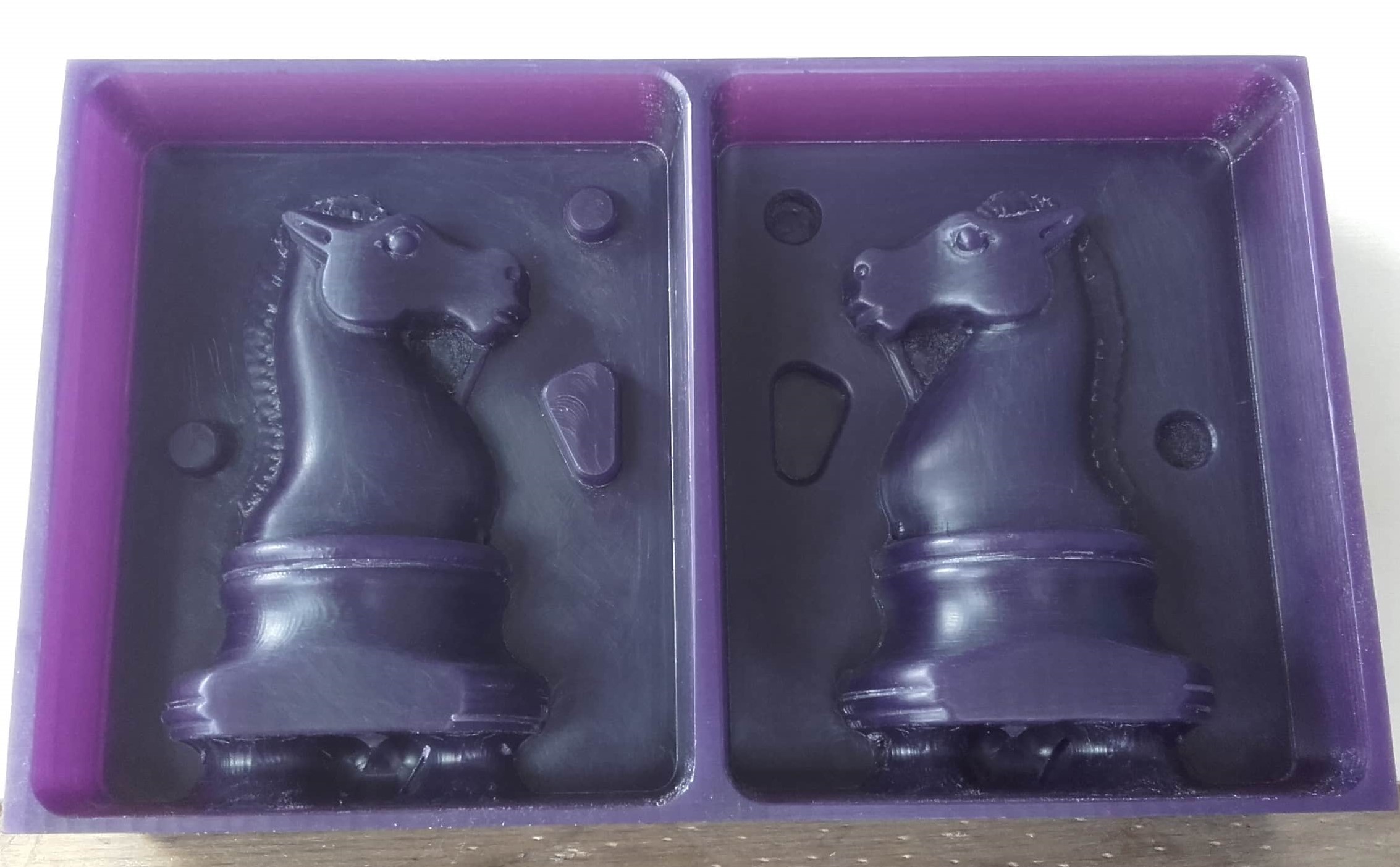
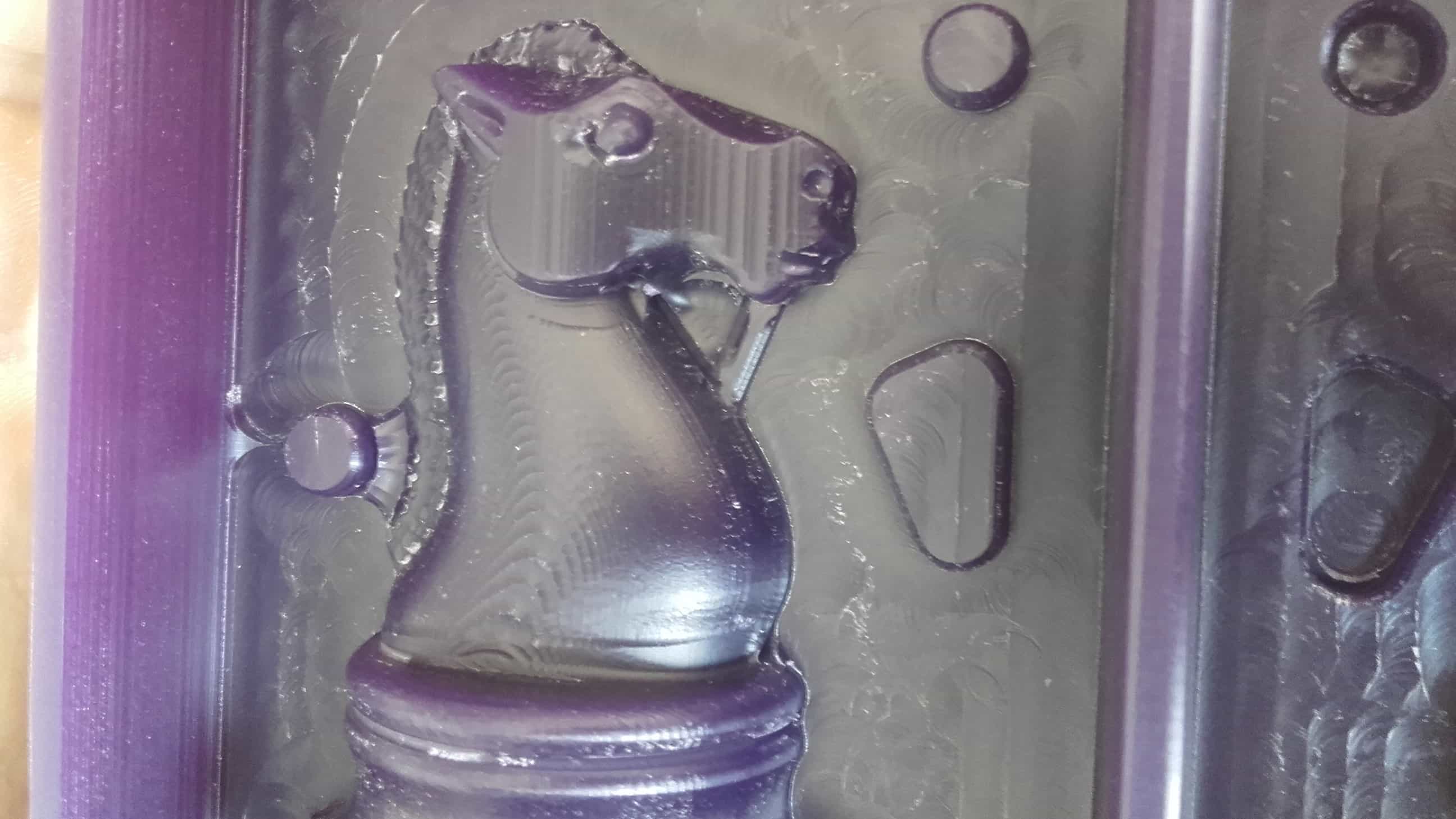
Success!
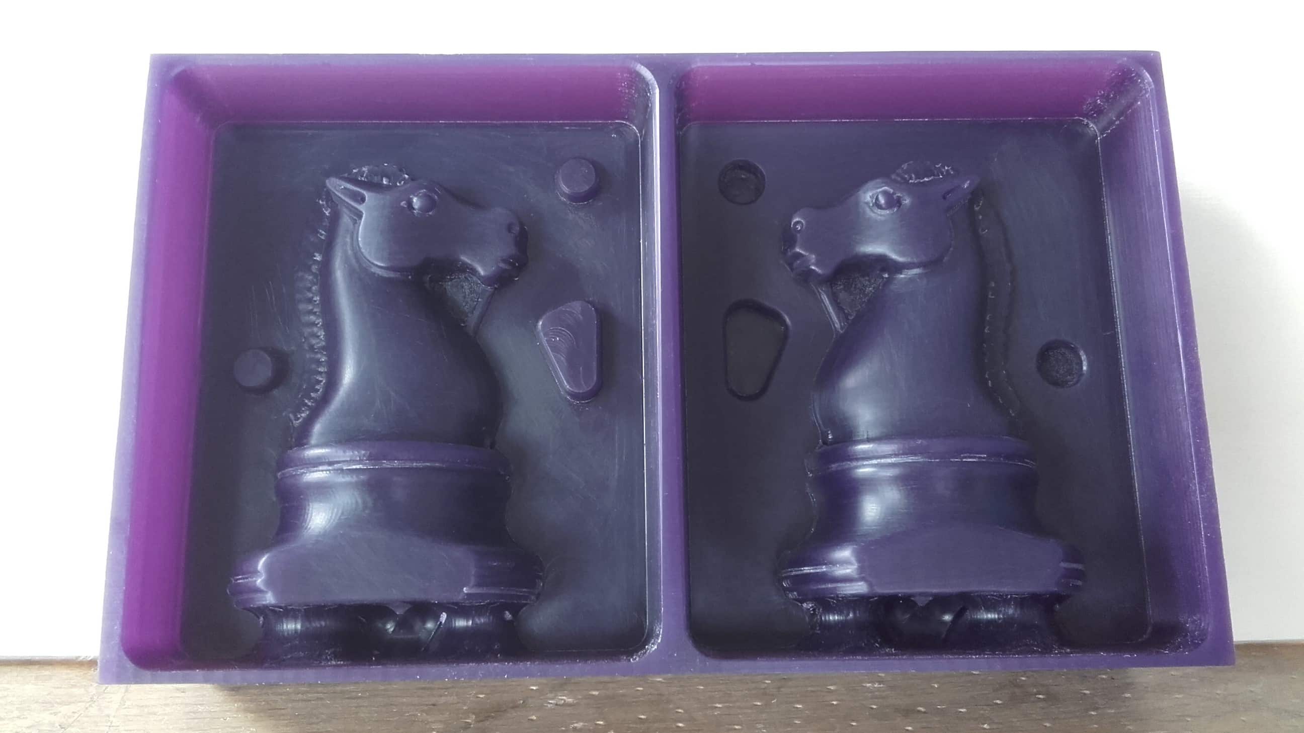
And after about an hour, the mold was looking all shiny and ready for casting.
Casting the Silicon Mold
The Pour
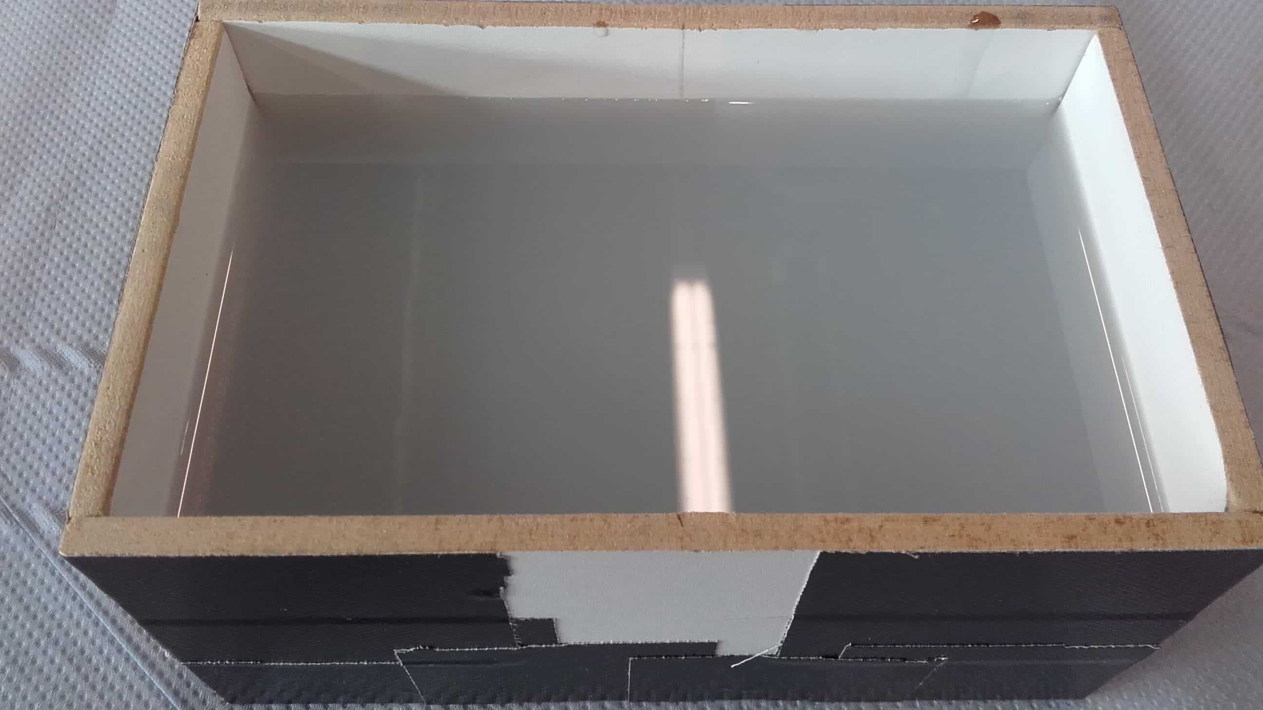
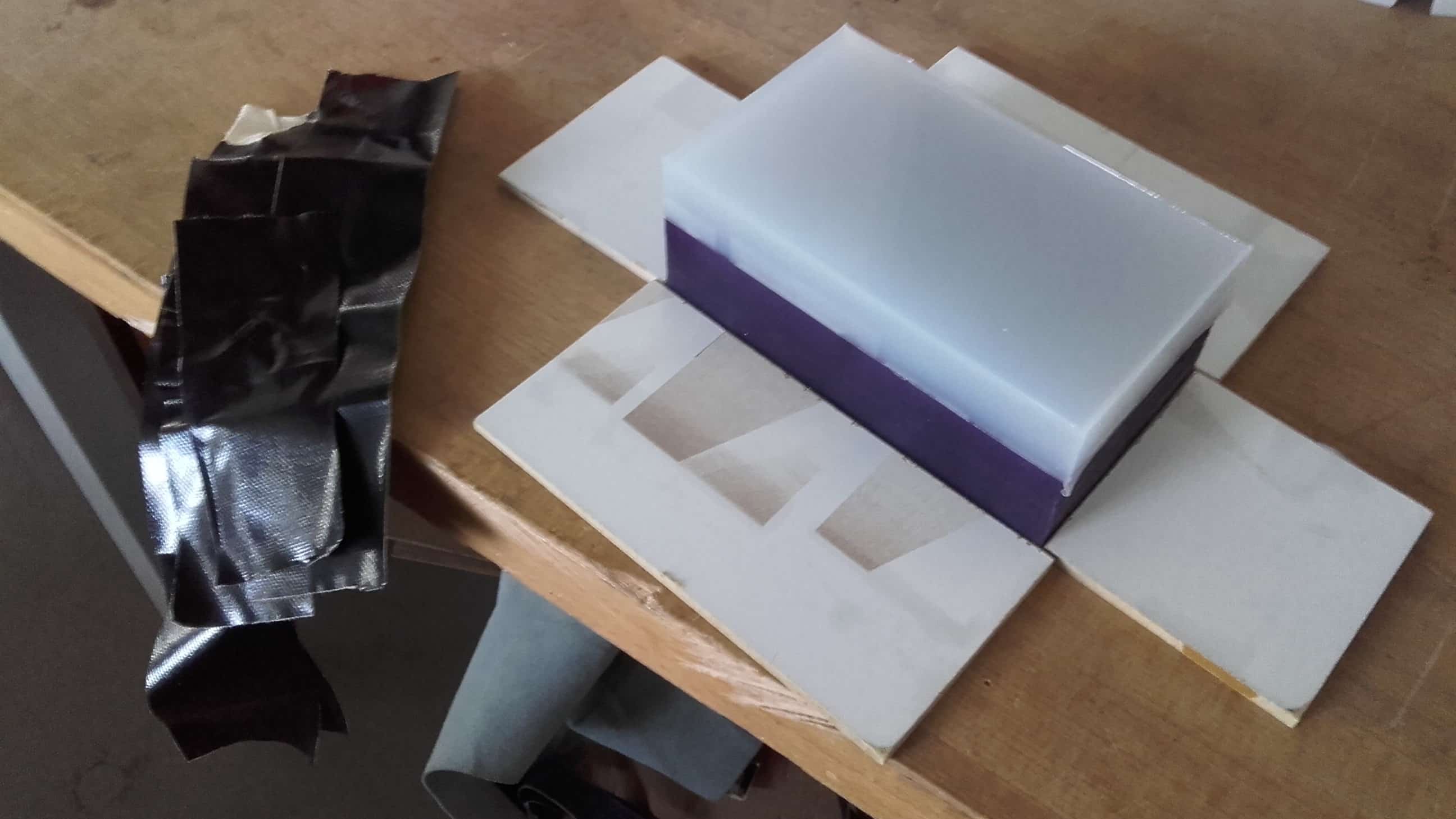
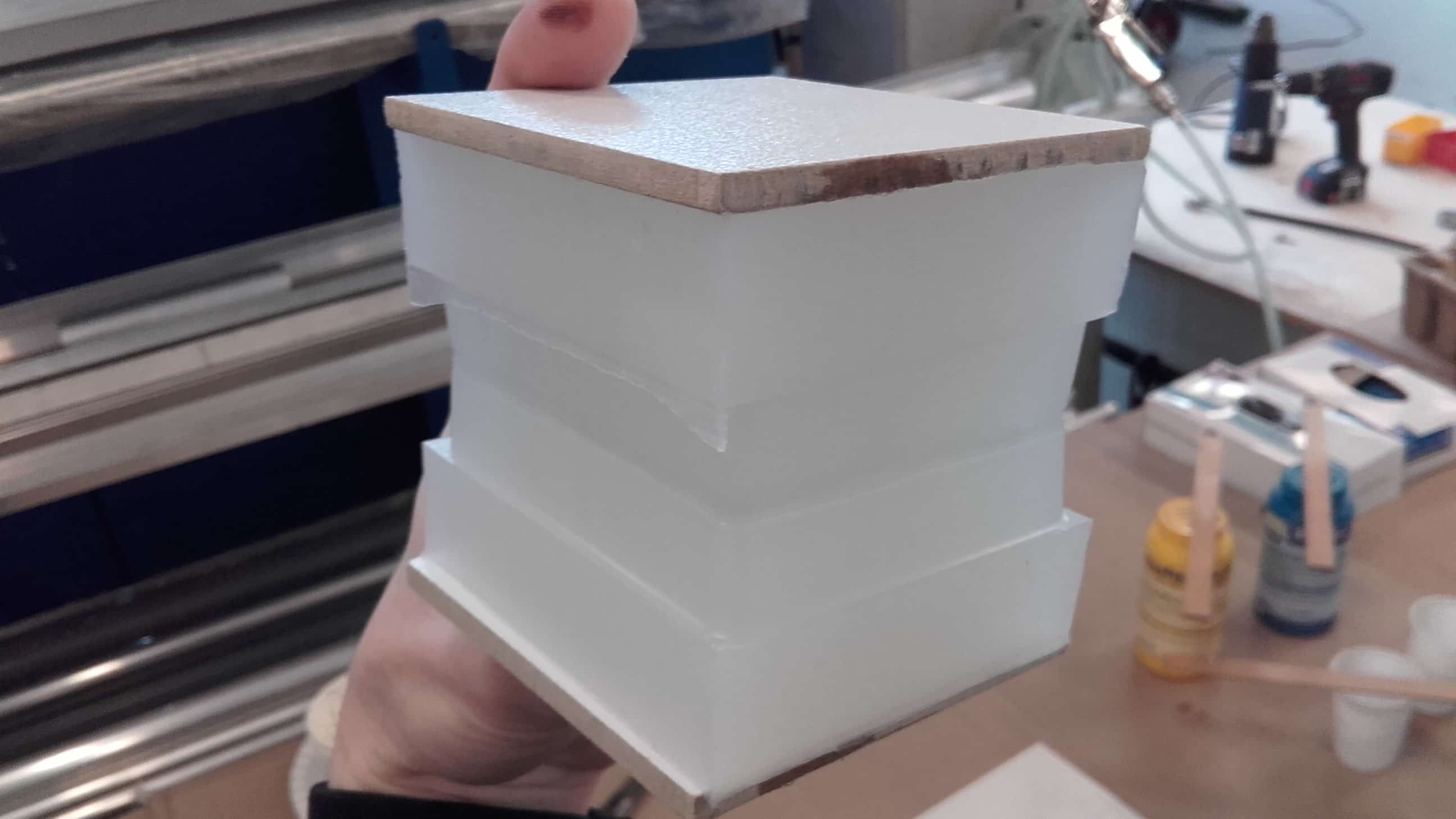
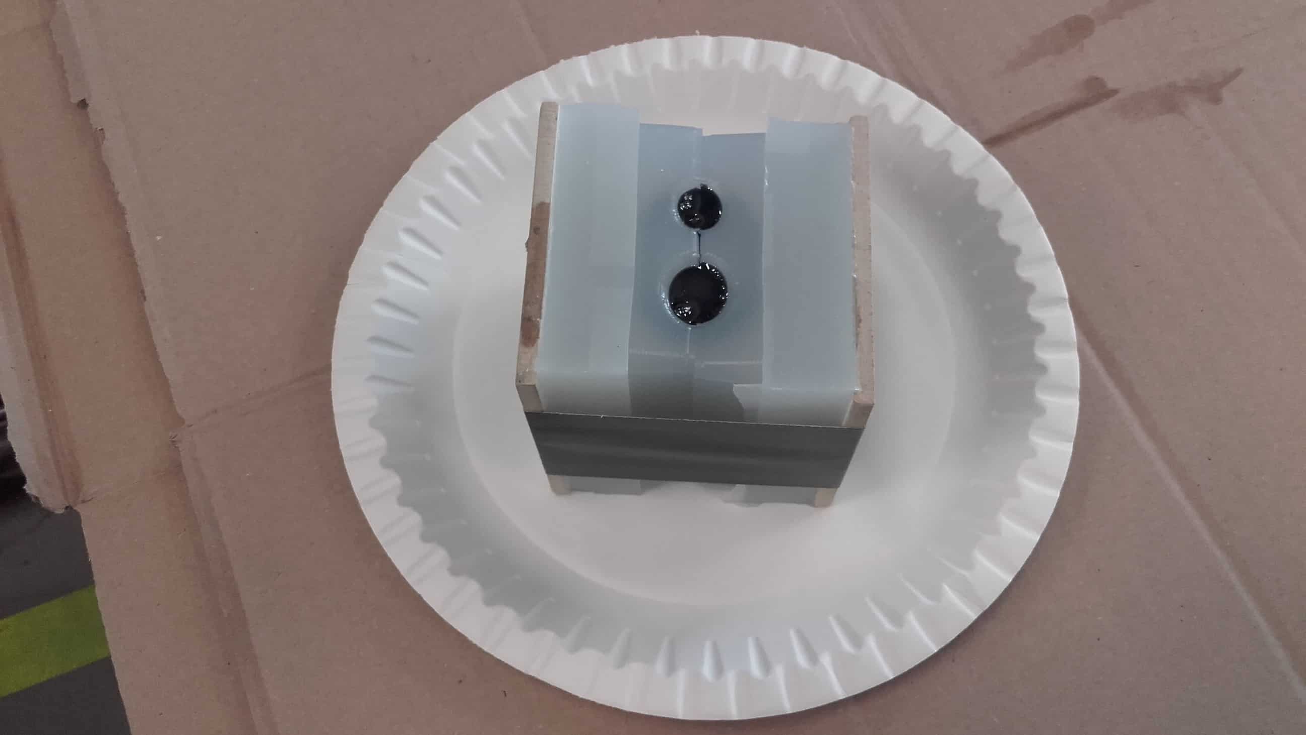
Making a Box
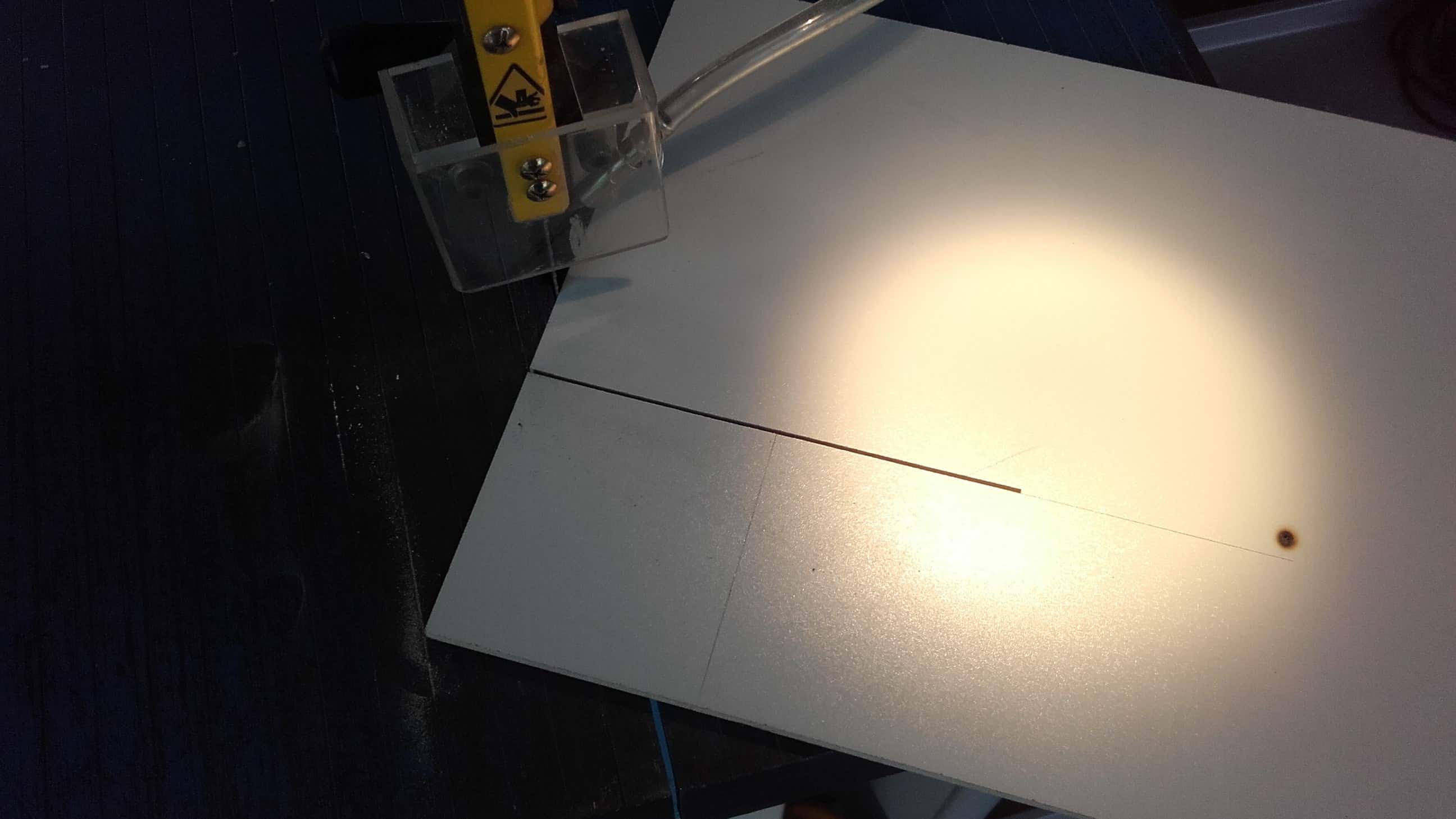
I started by making the box for my mold. We had some scrap dibond material with MDF sandwiched between two thin layers of plastic. It seems very low stick so that's why I chose it.
Box Made
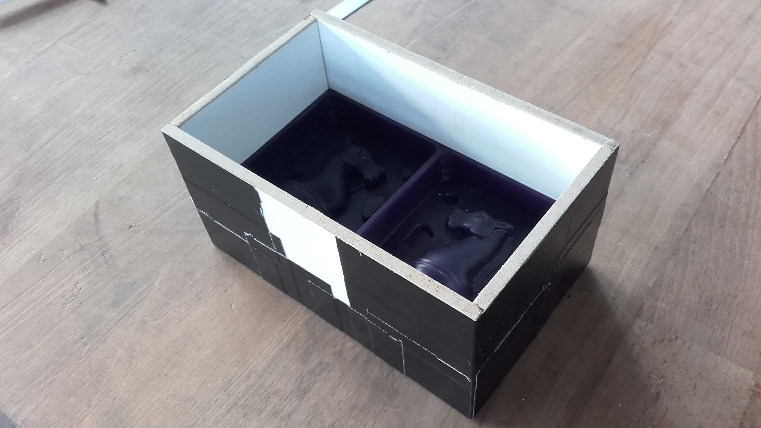
Then I used the handyman's secret weapon to put the pieces together and to seal the bottom. The silicone is not very viscous and I was confident it would be sufficient.
Mixing Station
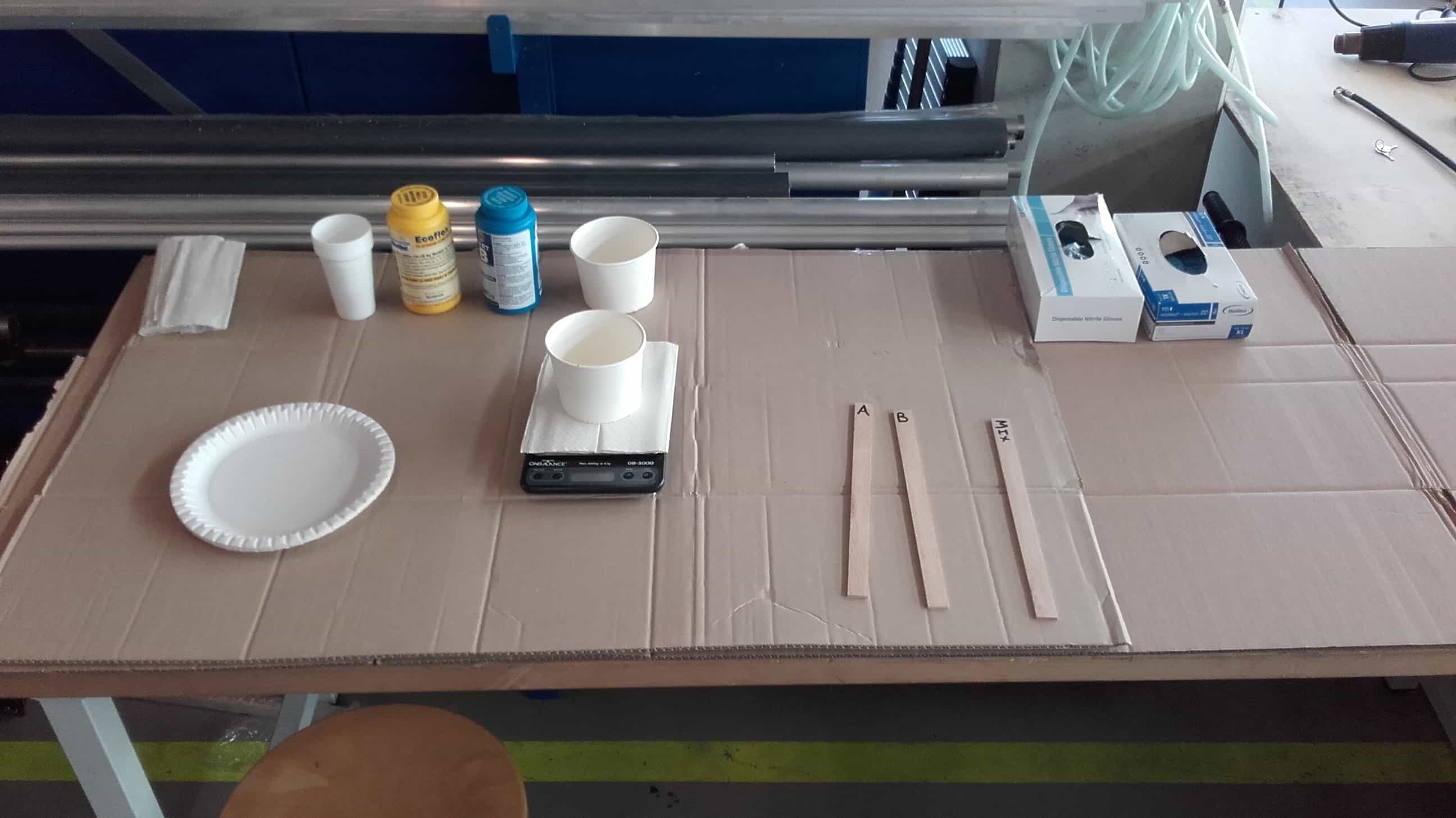
We set up a mixing station on one side of us...
Casting Station
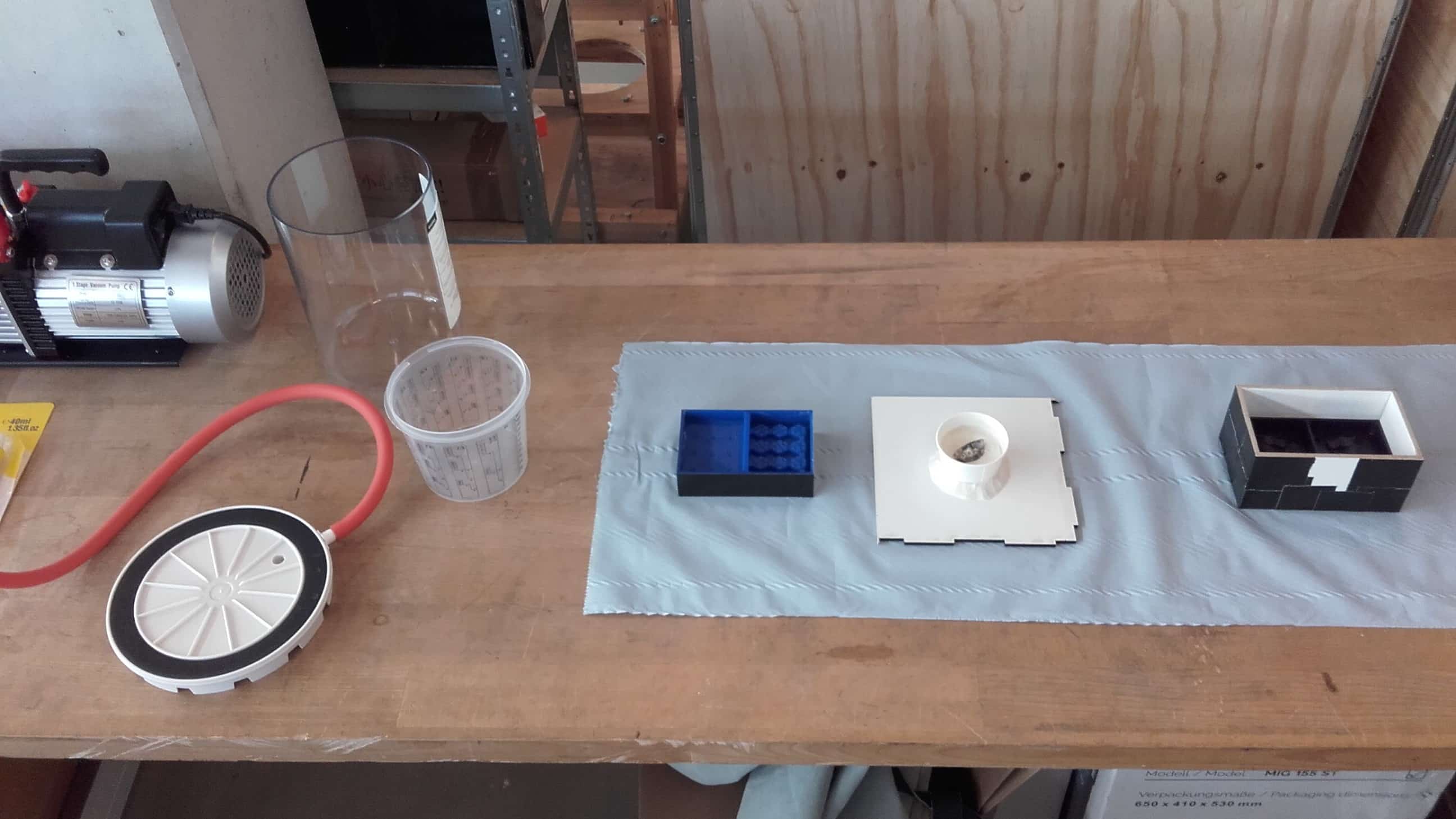
...and a vacuuming and casting station on the other side of us.
Oooh Chemicals 🤩
We carefully prepared for casting by reading the datasheet together and watching the how-to video from the website.
Stirring
And then we opened up the components and started mixing.
Blubbs
This silicone was very old so they were kind of chunky at first.
More Stirring
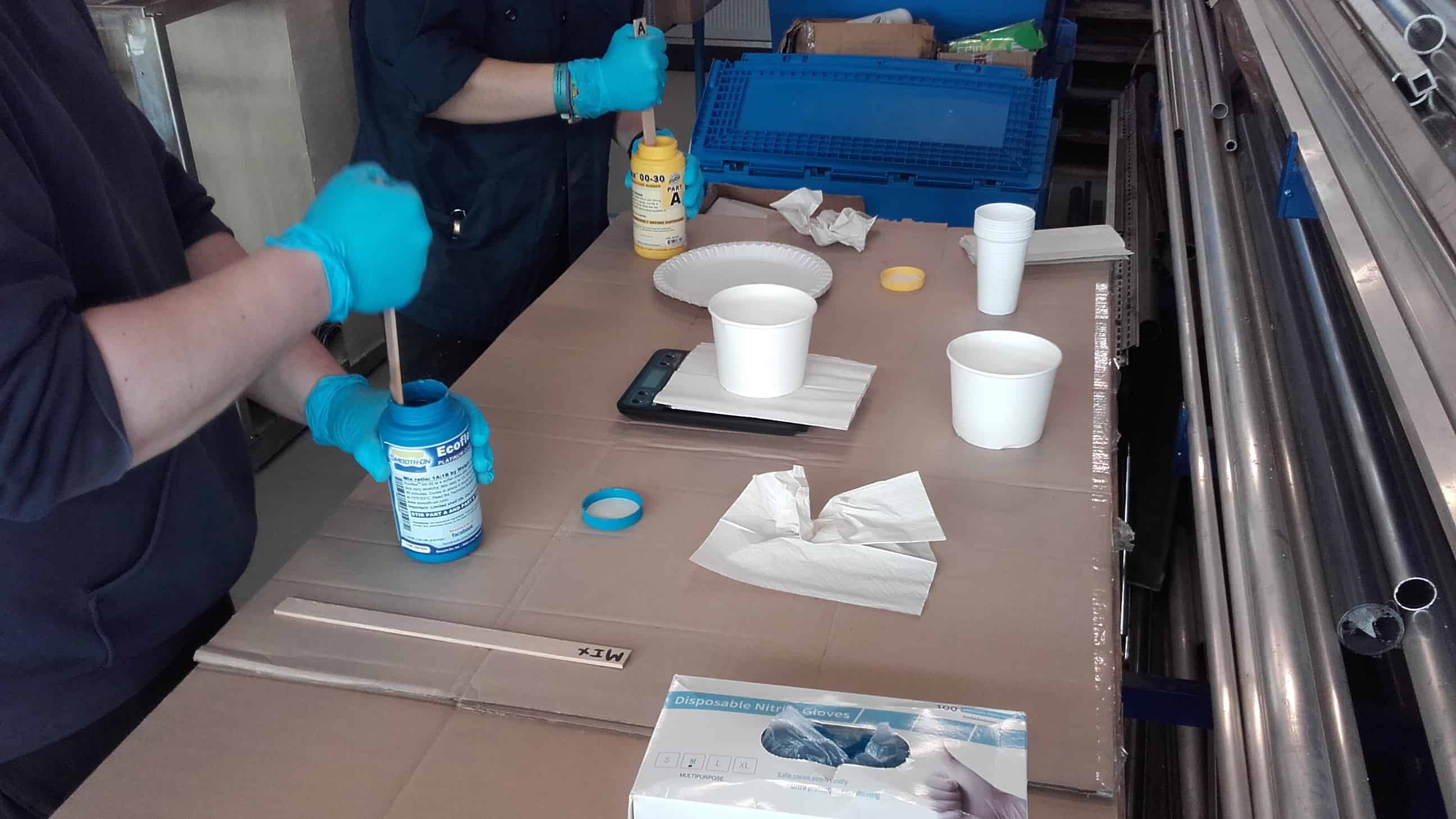
So we stirred and stirred some more until they were smooth and homogeneous.
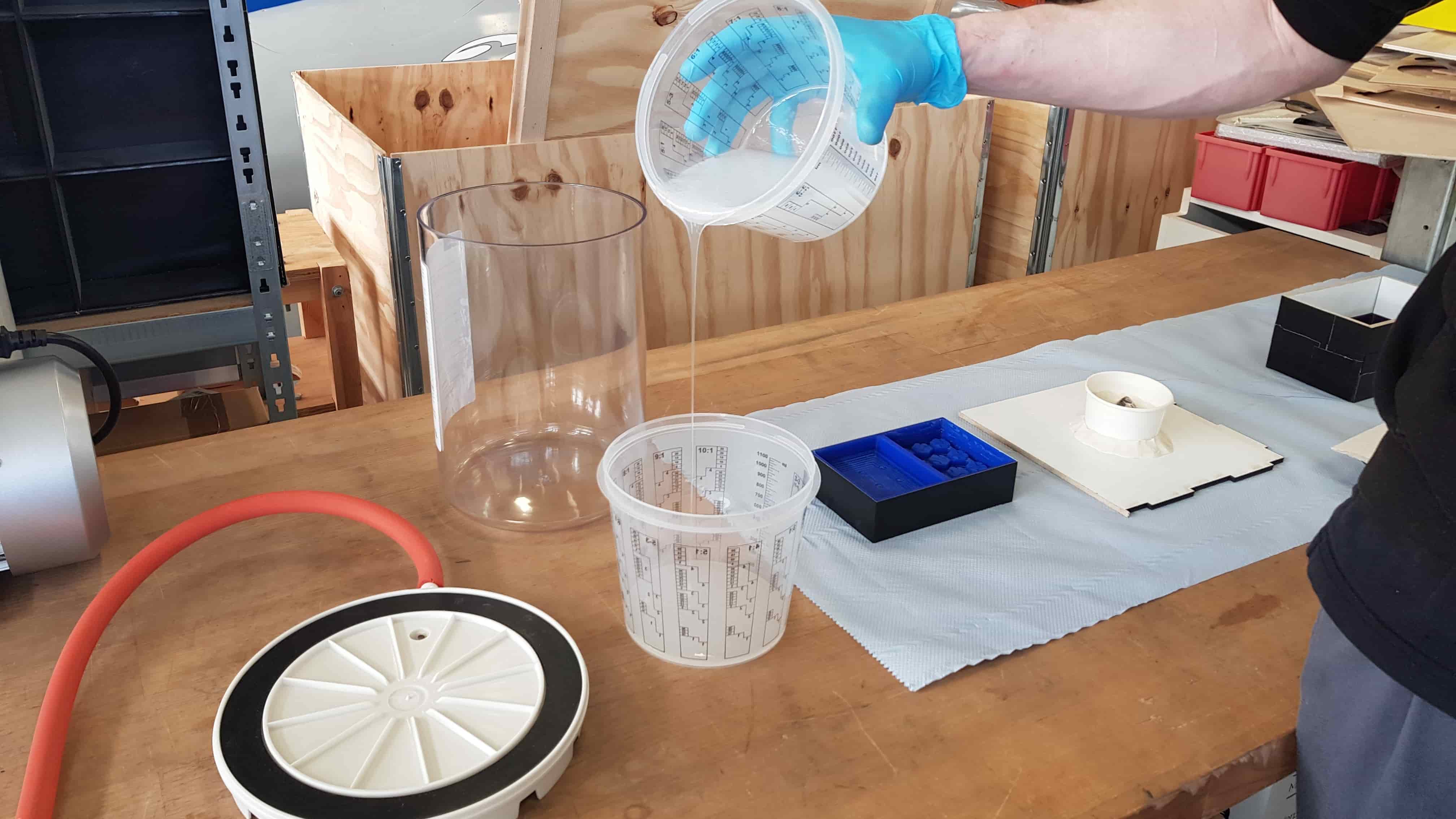
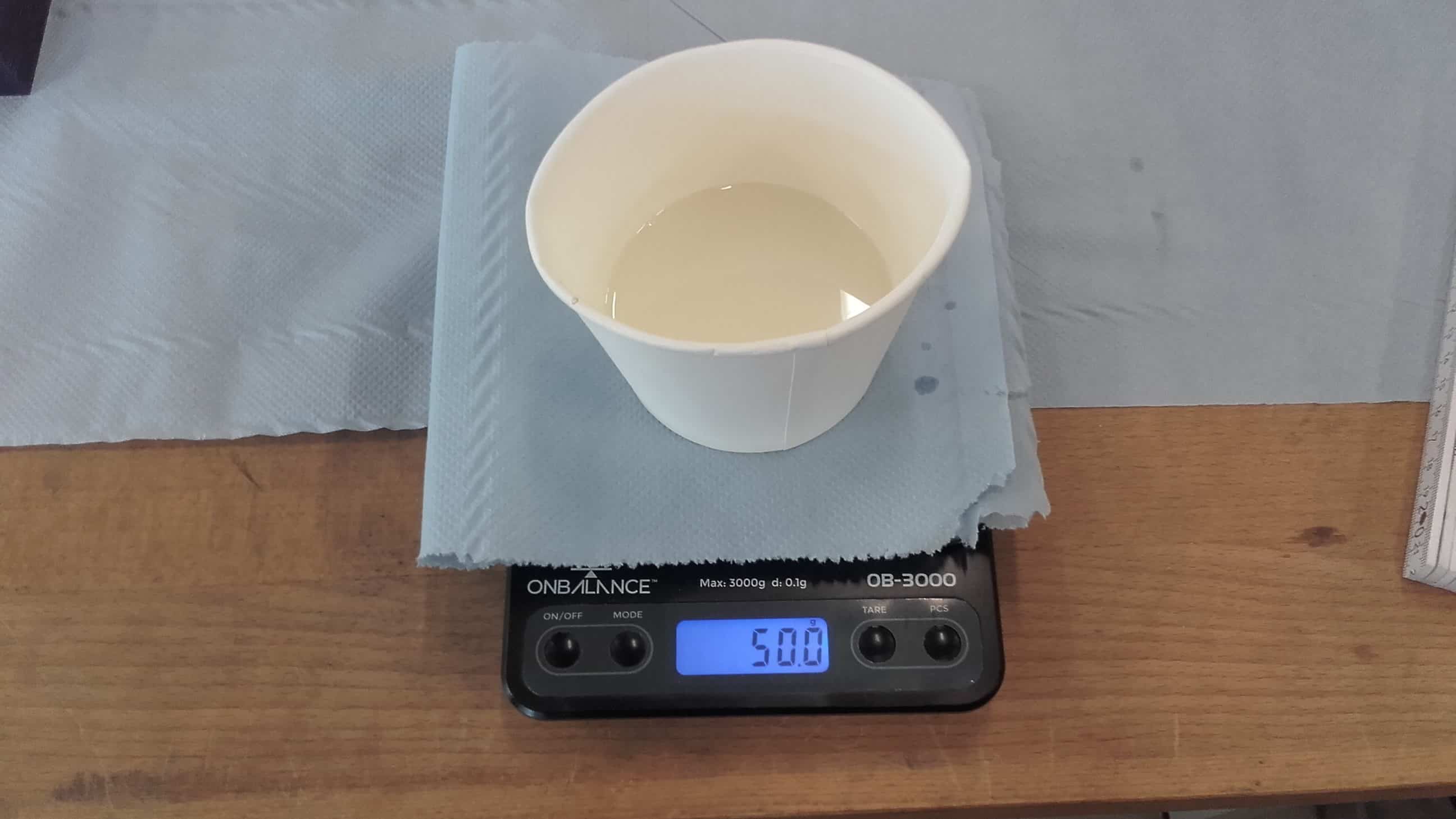
Weighing the Components
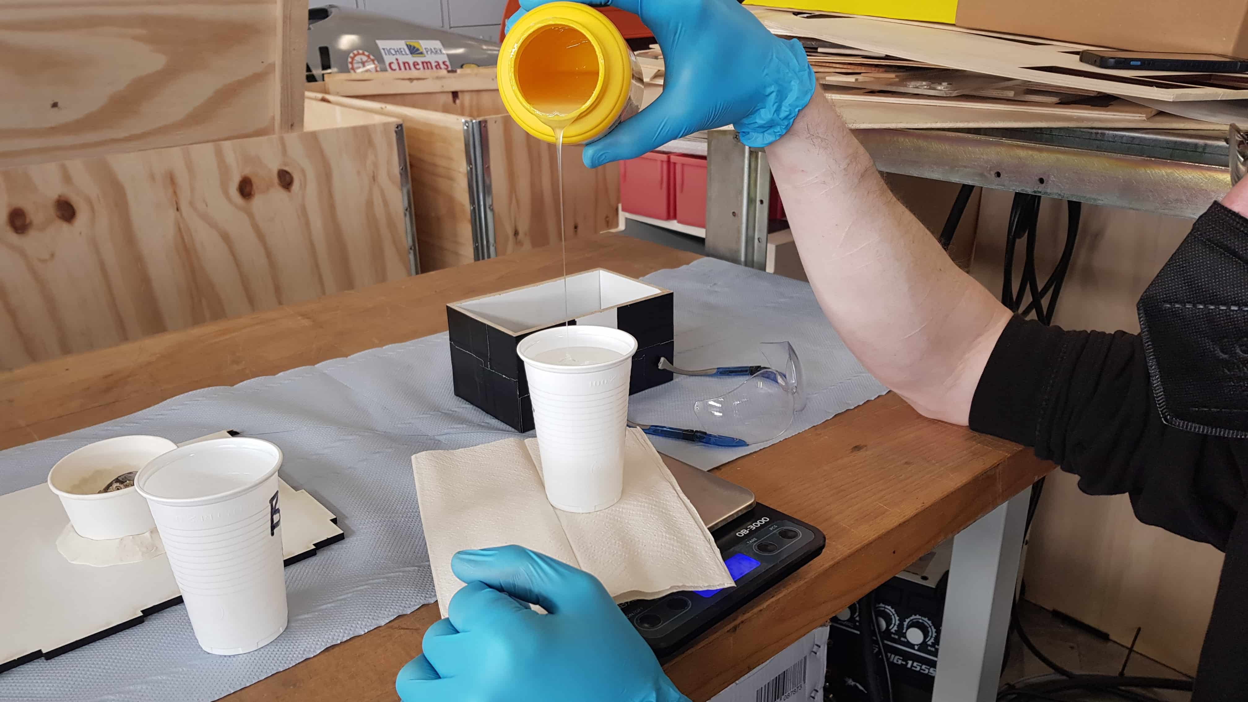
Then I carefully poured the first component into a disposable cup on the scale...
Exactly 200 ml
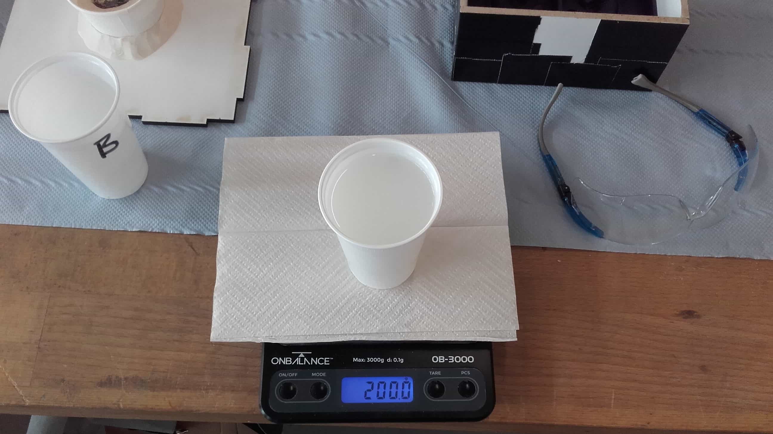
...until I got to exactly 200 ml. Technically this was only half what we needed for our three molds, but our new vacuum chamber is not large so we were afraid of spilling over with the bubbles while degassing.
Exactly 200 ml Again!
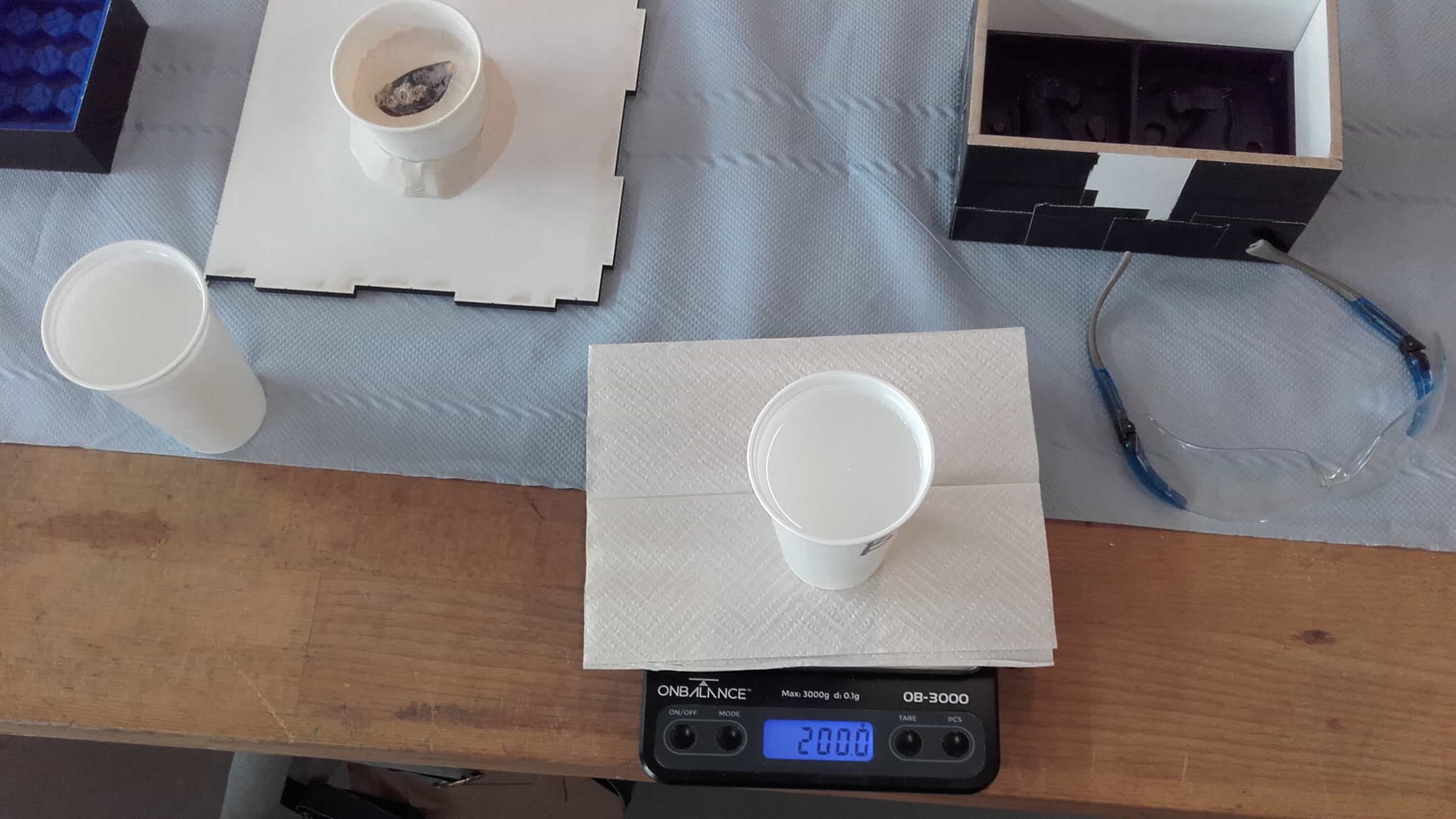
I repeated the process for the second component to meet the required 1:1 ratio. All three of our OCD's were seriously twitching during this pour. 😂
Combining the Components
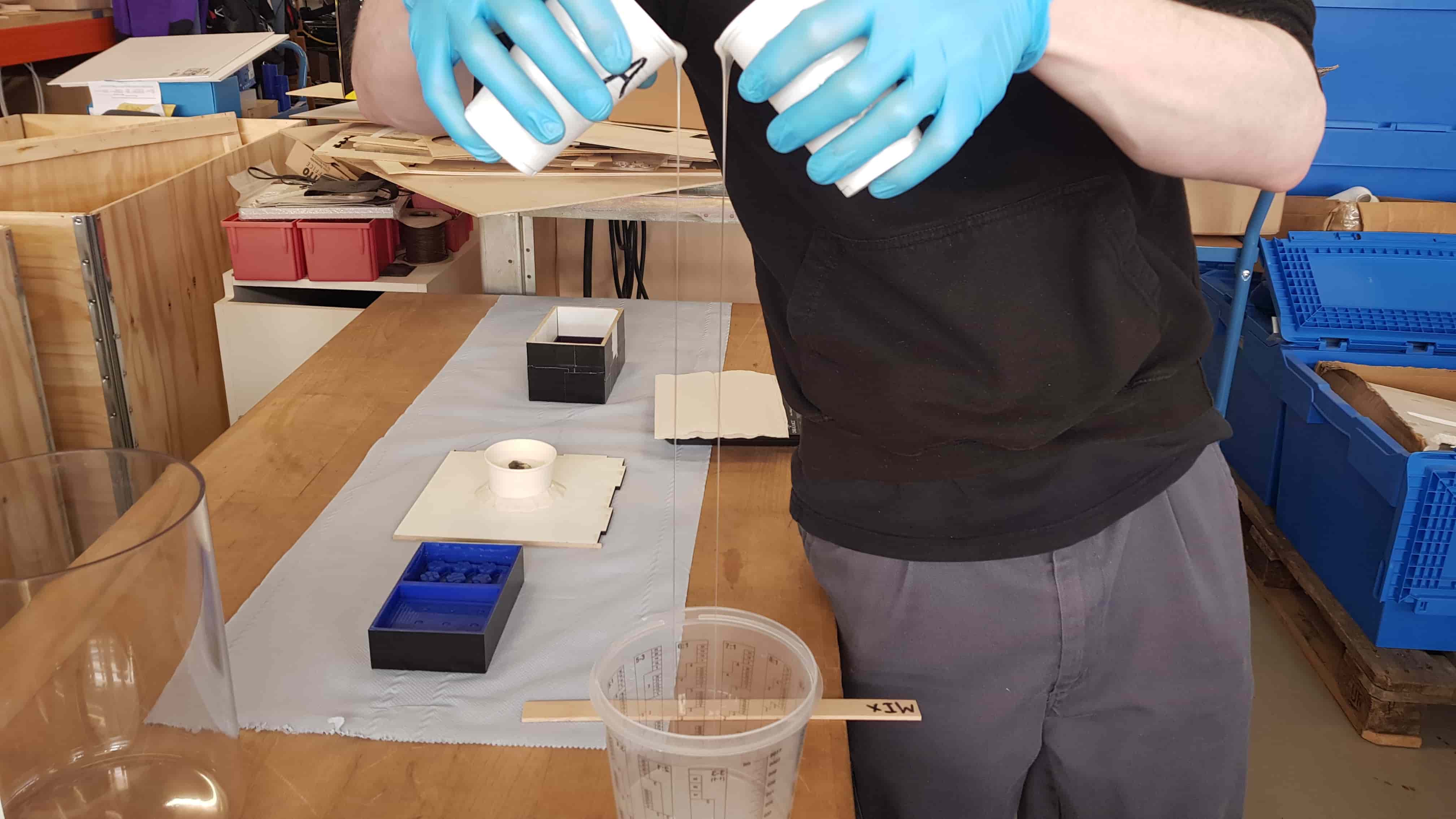
Then I poured both components into a new container for mixing. Degassing was the next step, so the long bead here is unnecessary, but it was more fun to do.
Every Last Drop
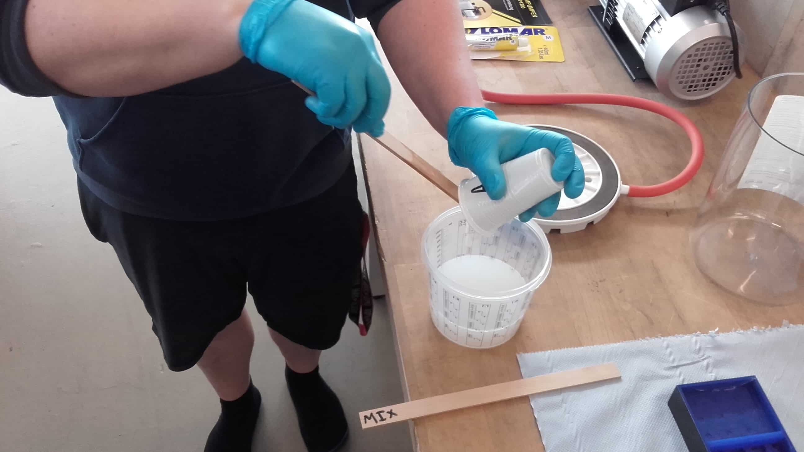
We carefully scraped everything we could get out of the cups...
Even More Stirring
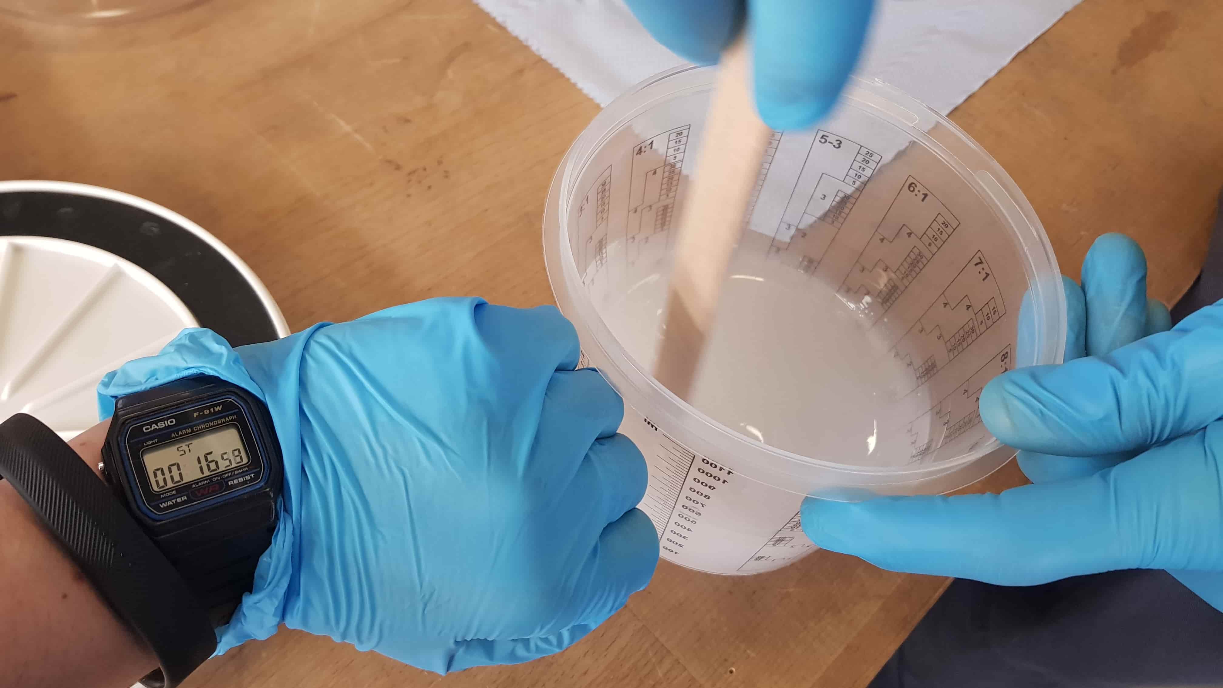
...and then started stirring once again, this time for three minutes per the instructions.
One More Container
We transferred the mixture one more time to leave behind any unmixed material that may have been clinging to the sides of the first mixing container.
Degassing
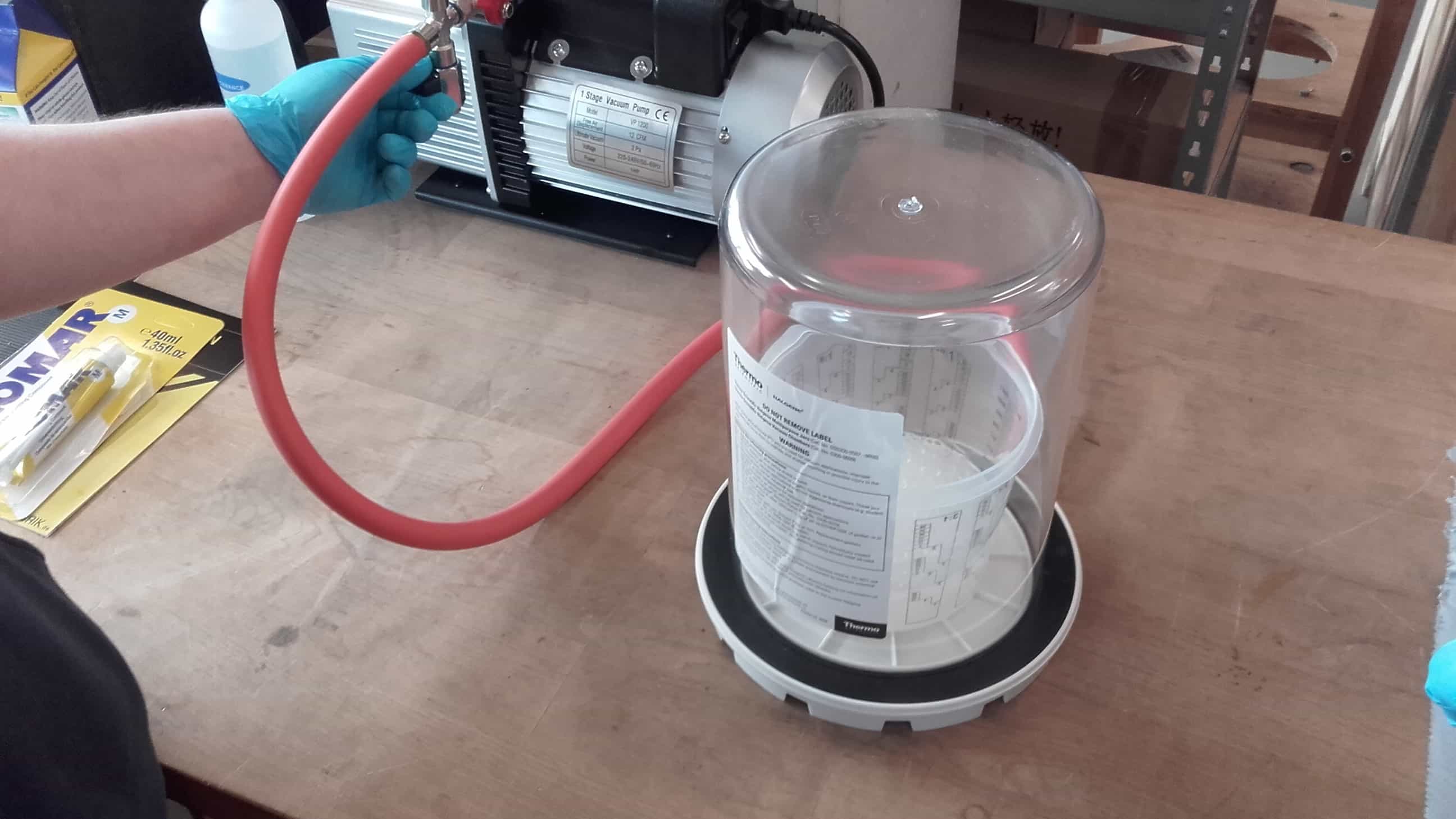
And then we were into the vacuum chamber to degass the mixture for three minutes.
Finally Casting!

Once degassed, it was time for the real deal.
But Slowly
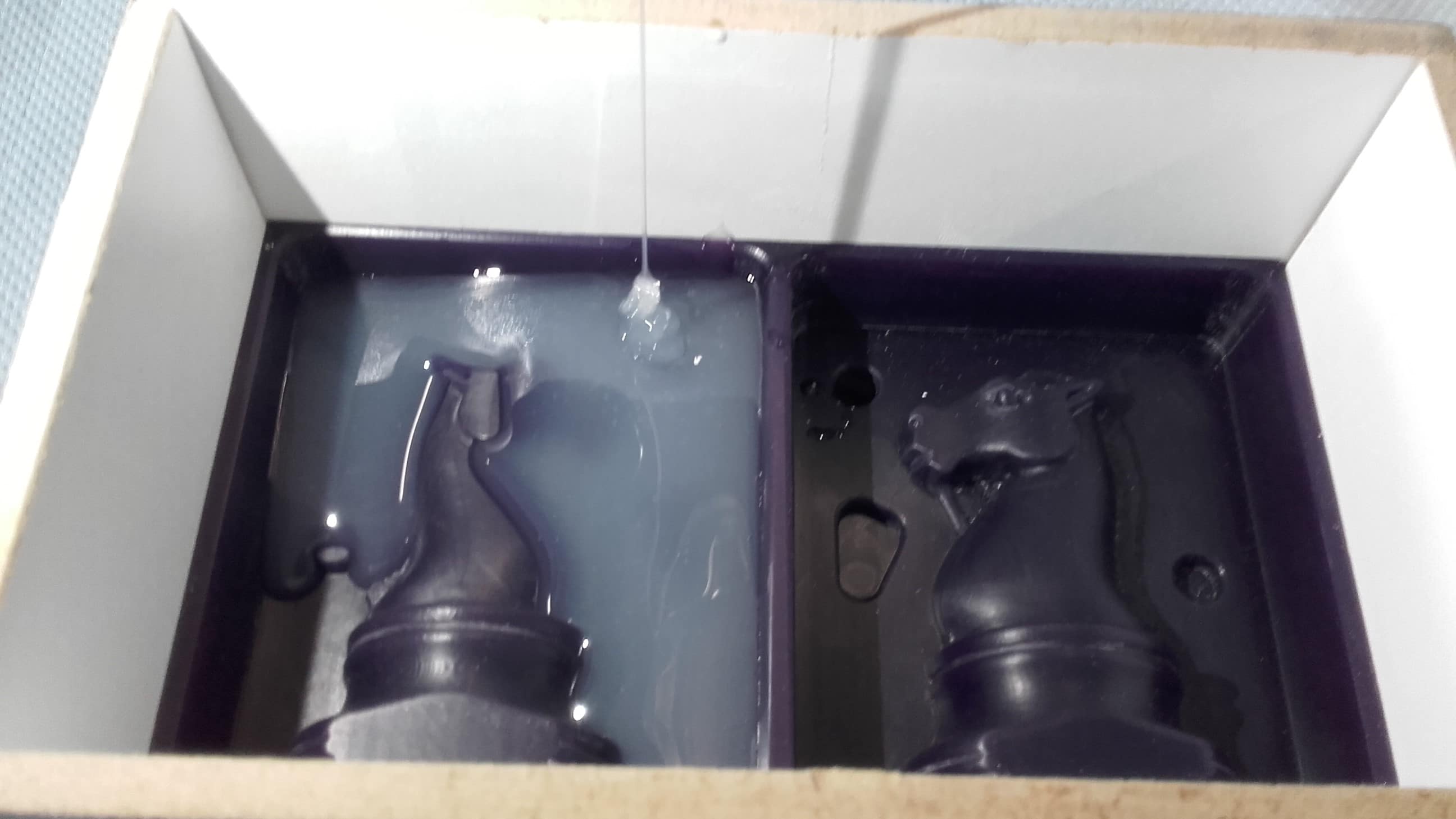
I poured the silicone into the deepest part of the mold as carefully as I could and let it slowly make its own way into all the other details.
Batch No. 2
With the first batch, I only had enough silicone to barely cover my model, so we mixed up another 400 ml using the exact same process. Fortunately this stuff has a 45 minute pot life so there was no big rush or anxiety.
So Far, So, Good
At this point, everything was looking good. Now we just had to wait four hours for it to cure.
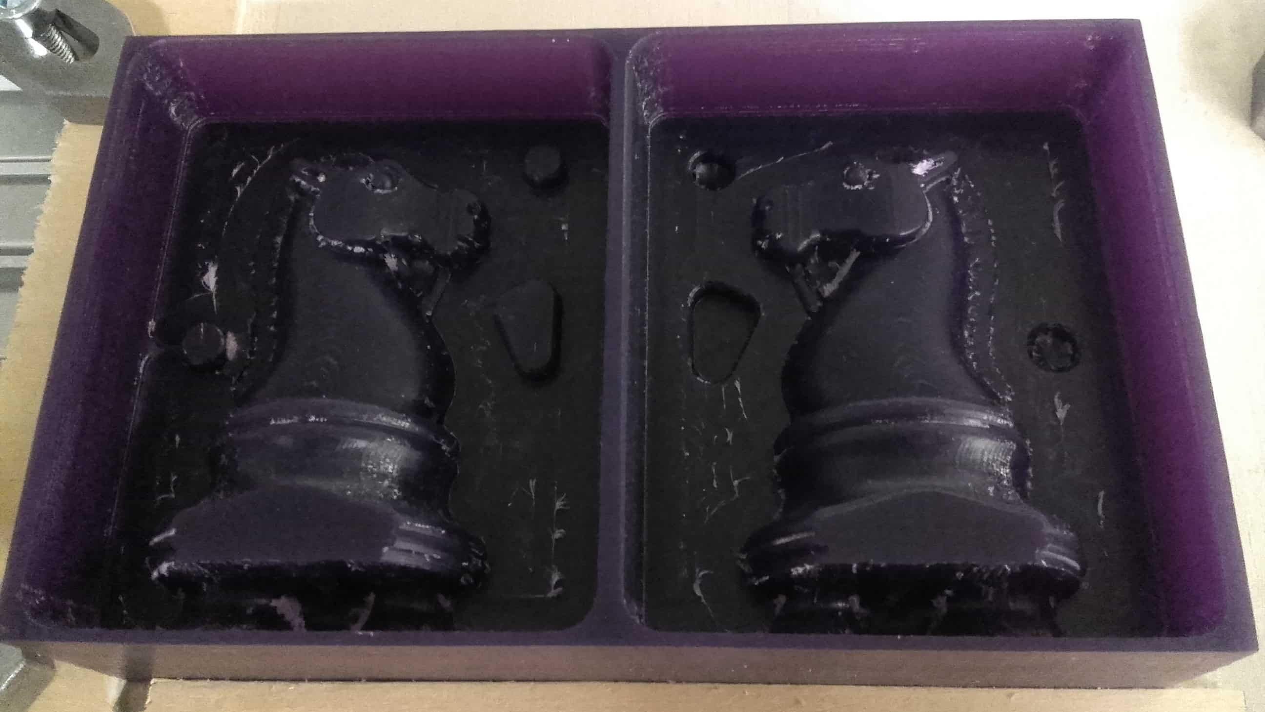
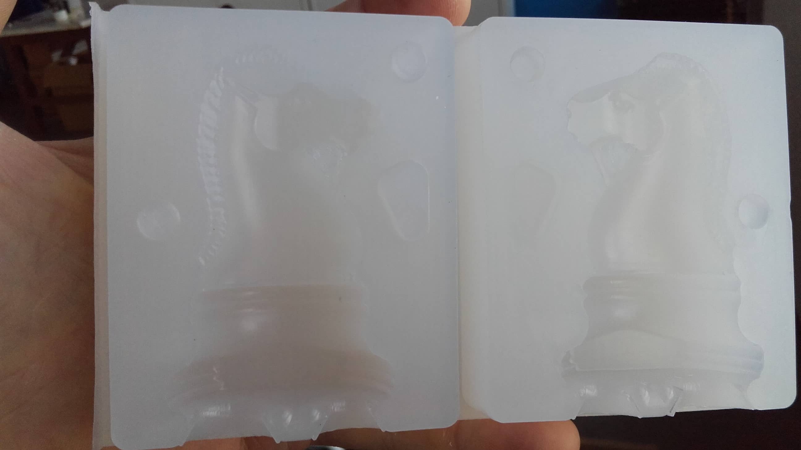
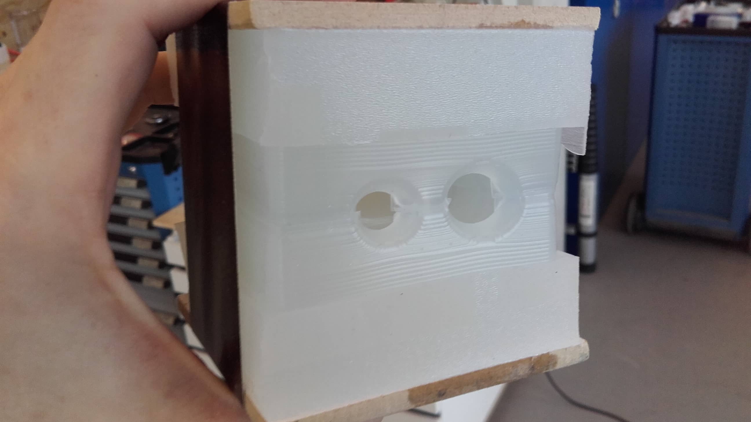
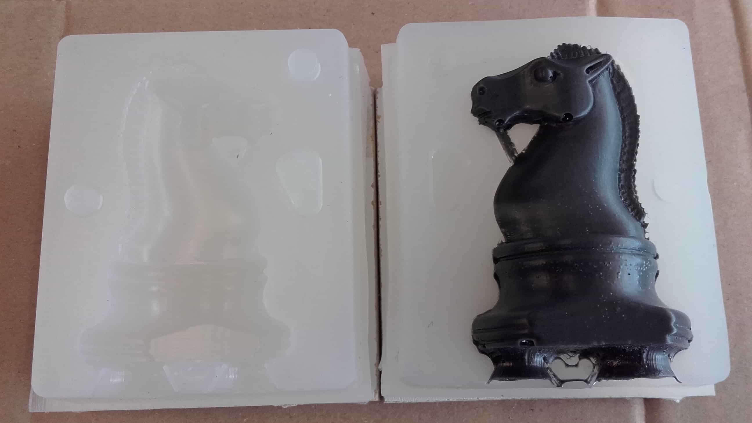
De-Molding
Taking the Mold Apart
The mold came apart easily.
Looking Good
And the finished parts were looking great.
Casting the Resin
Splitting the Halves
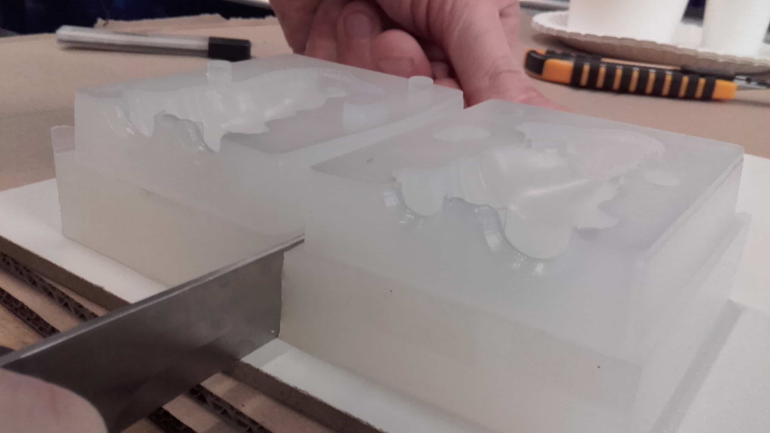
I separated the two halves with a kitchen knife.
Fitting Them Together
And then fitted them together the best that I could. The silicon is very flexible, but it also kind of sticks to itself so it was difficult to get a good alignment.
Finished Mold
Unfortunately, I could only gage the alignment of the mold based on the alignment of the sprue holes, but I taped the parts together.
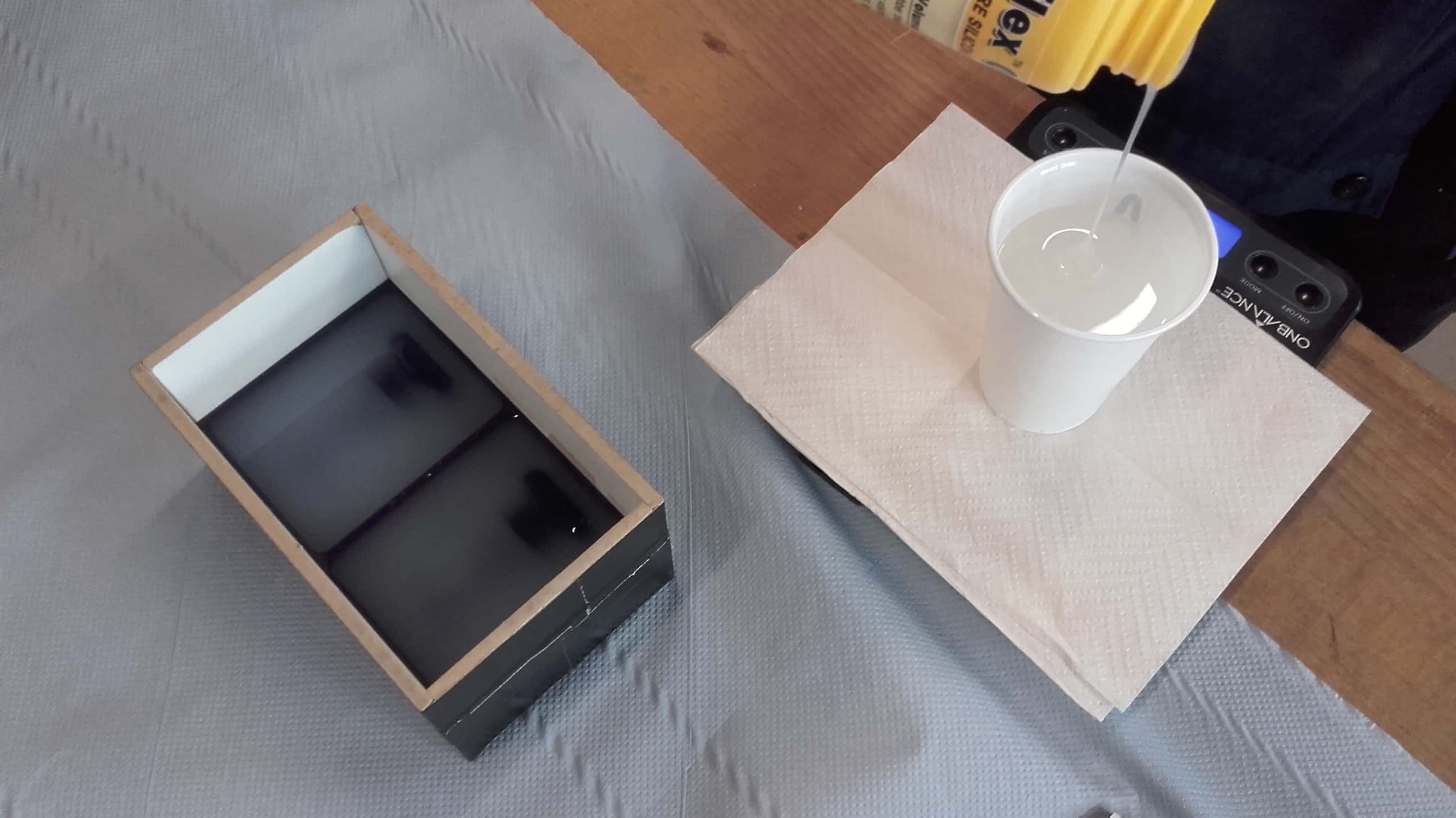
Supplies
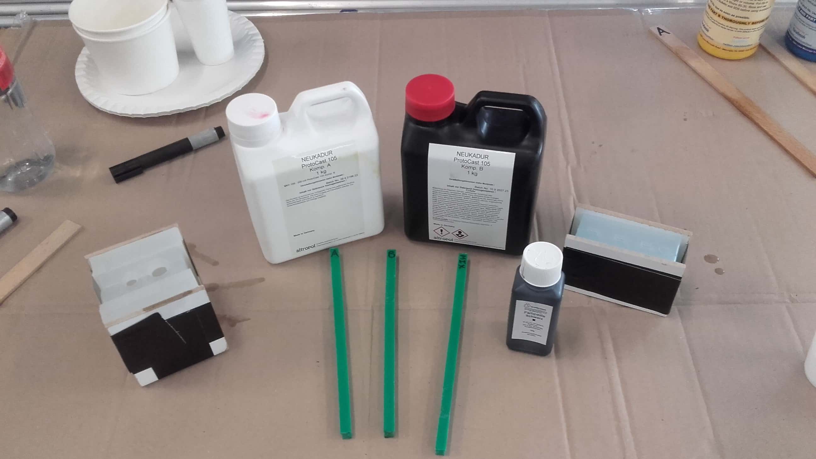
And then collected all of the materials that would be needed for casting the resin.
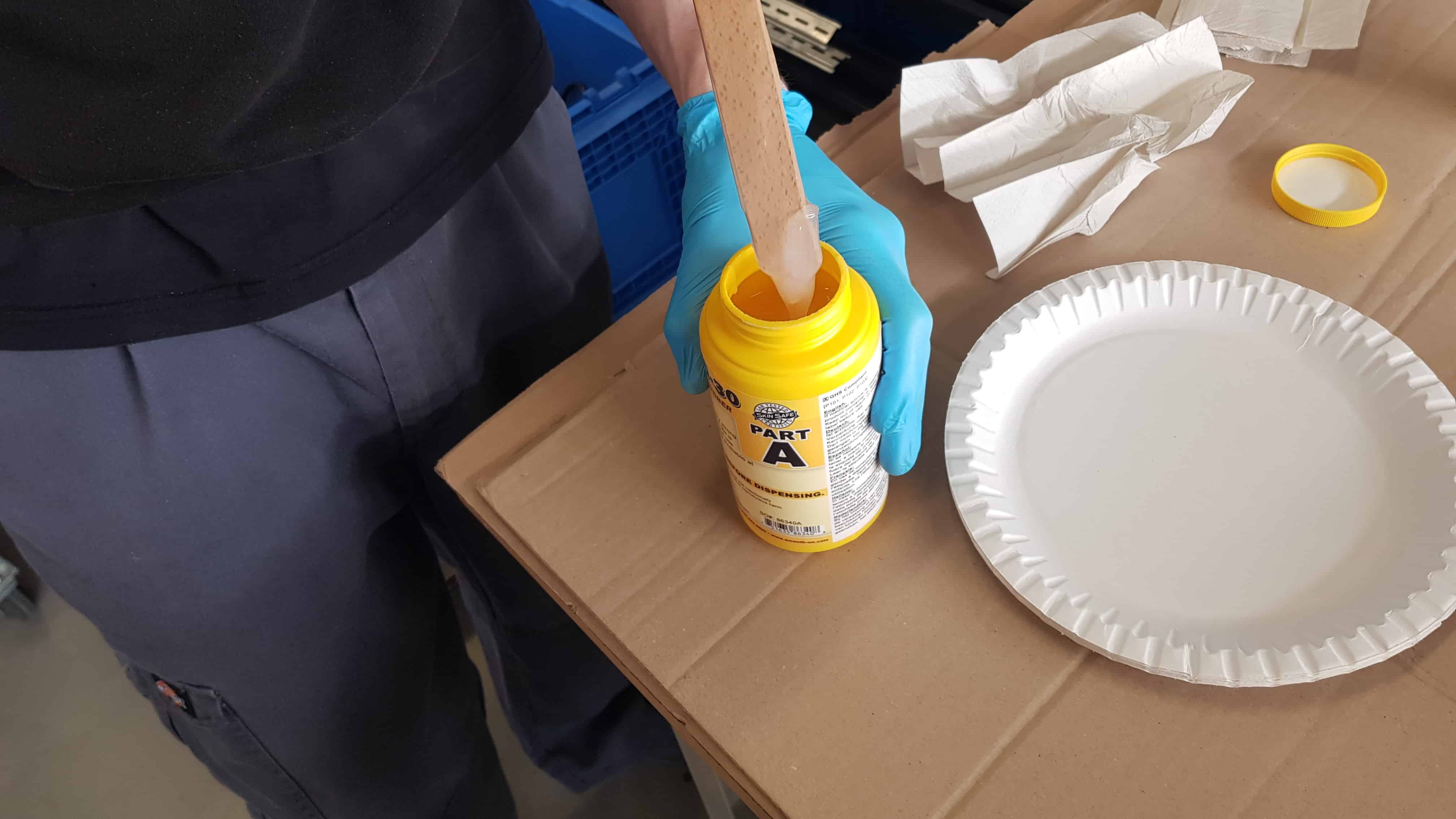
Measuring and Mixing
I carefully measured and mixed the epoxy, also adding a bit of black pigment.
Degassing
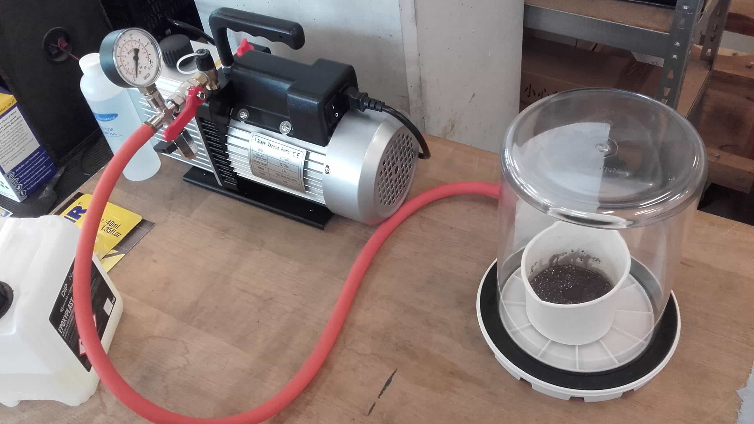
Then I degassed the mix according to the instructions on the datasheet,
Casting
and poured the resin until the mold was full.
Taking a Look at the Results
The resin cured quickly so I didn't have too long to wait, and the two halves of the mold separated easily.
Slightly Misaligned
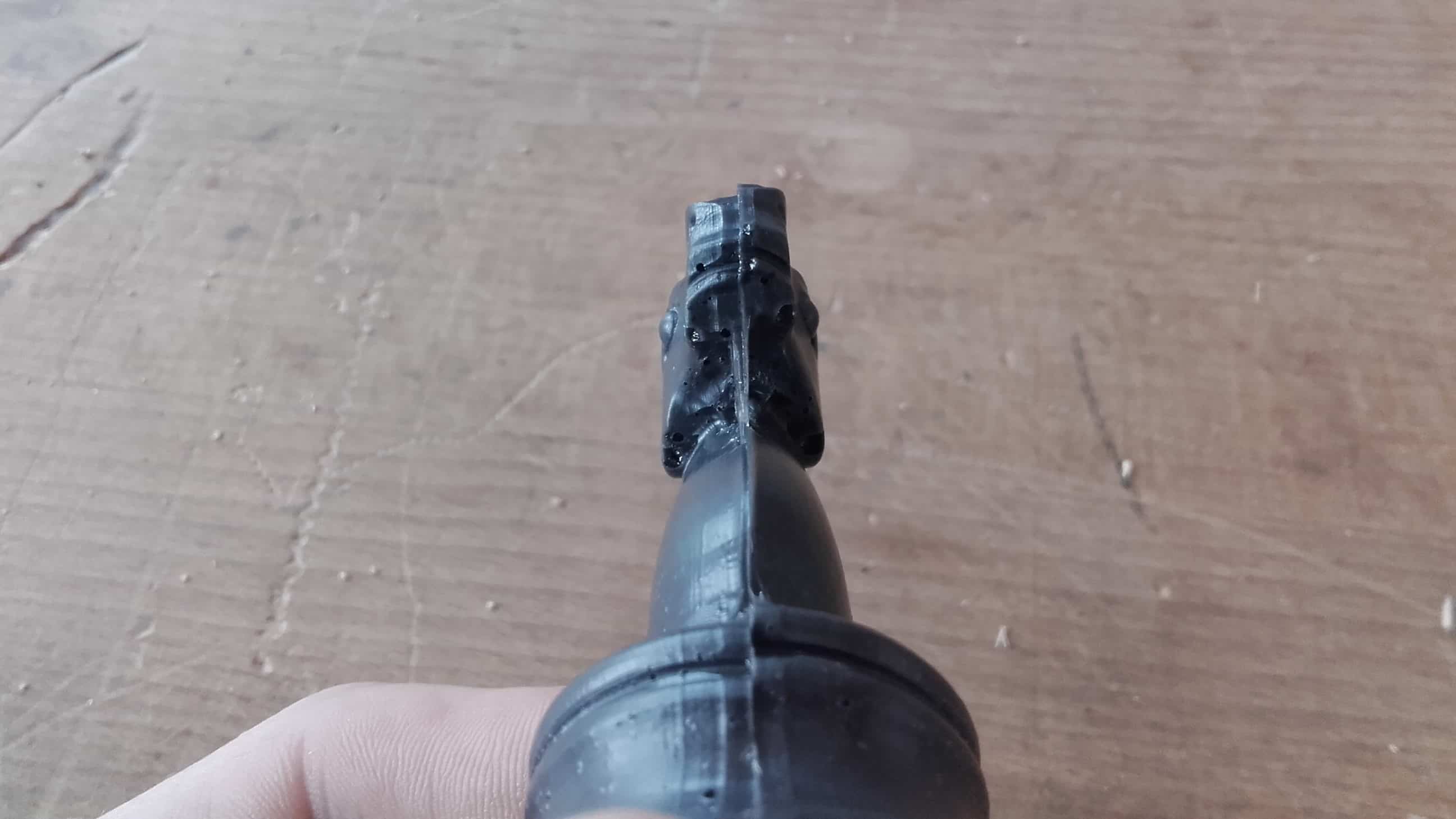
Unfortunately the two halves were slightly misaligned, but the extra air channels worked perfectly.
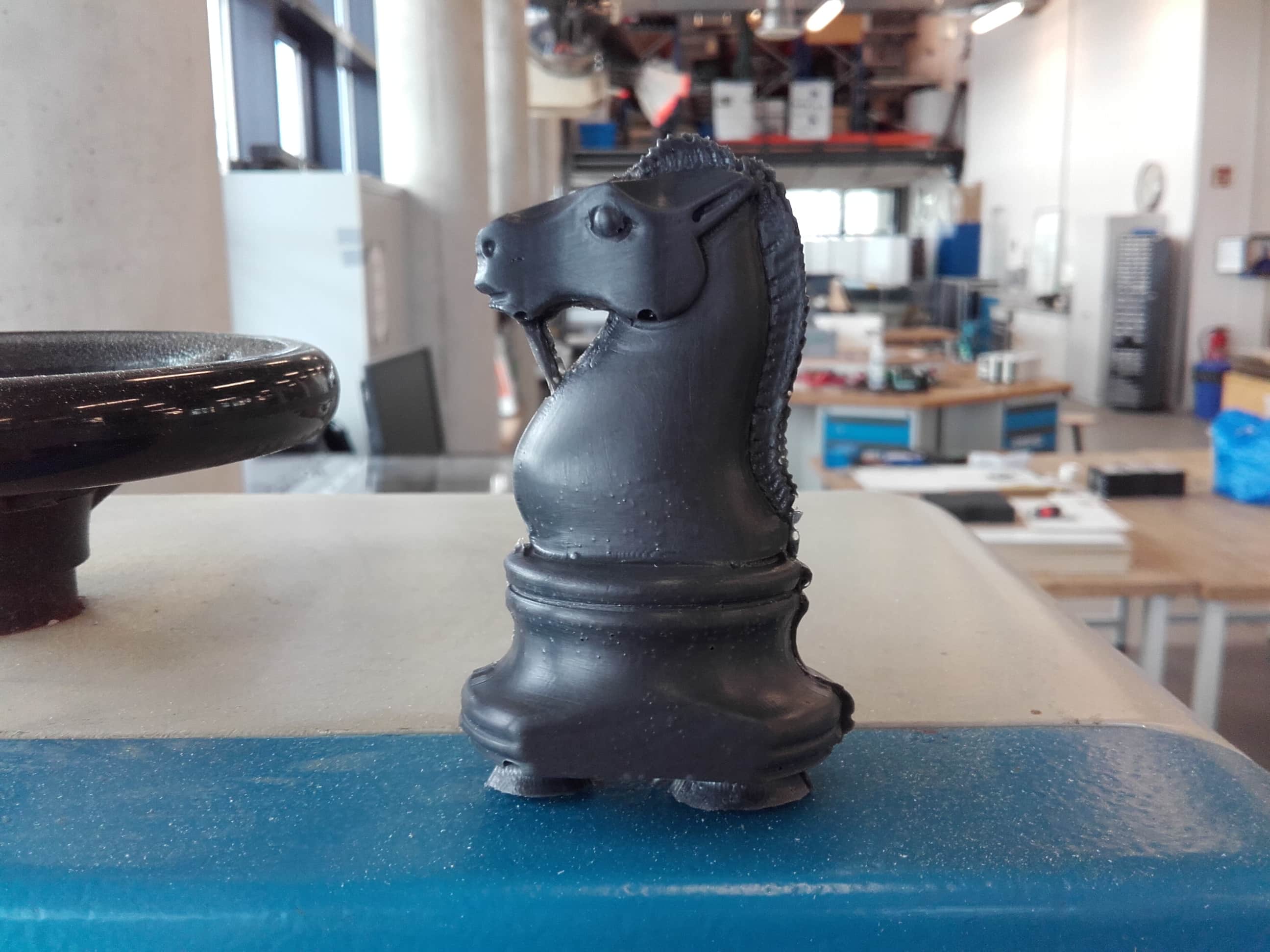
Overall Success
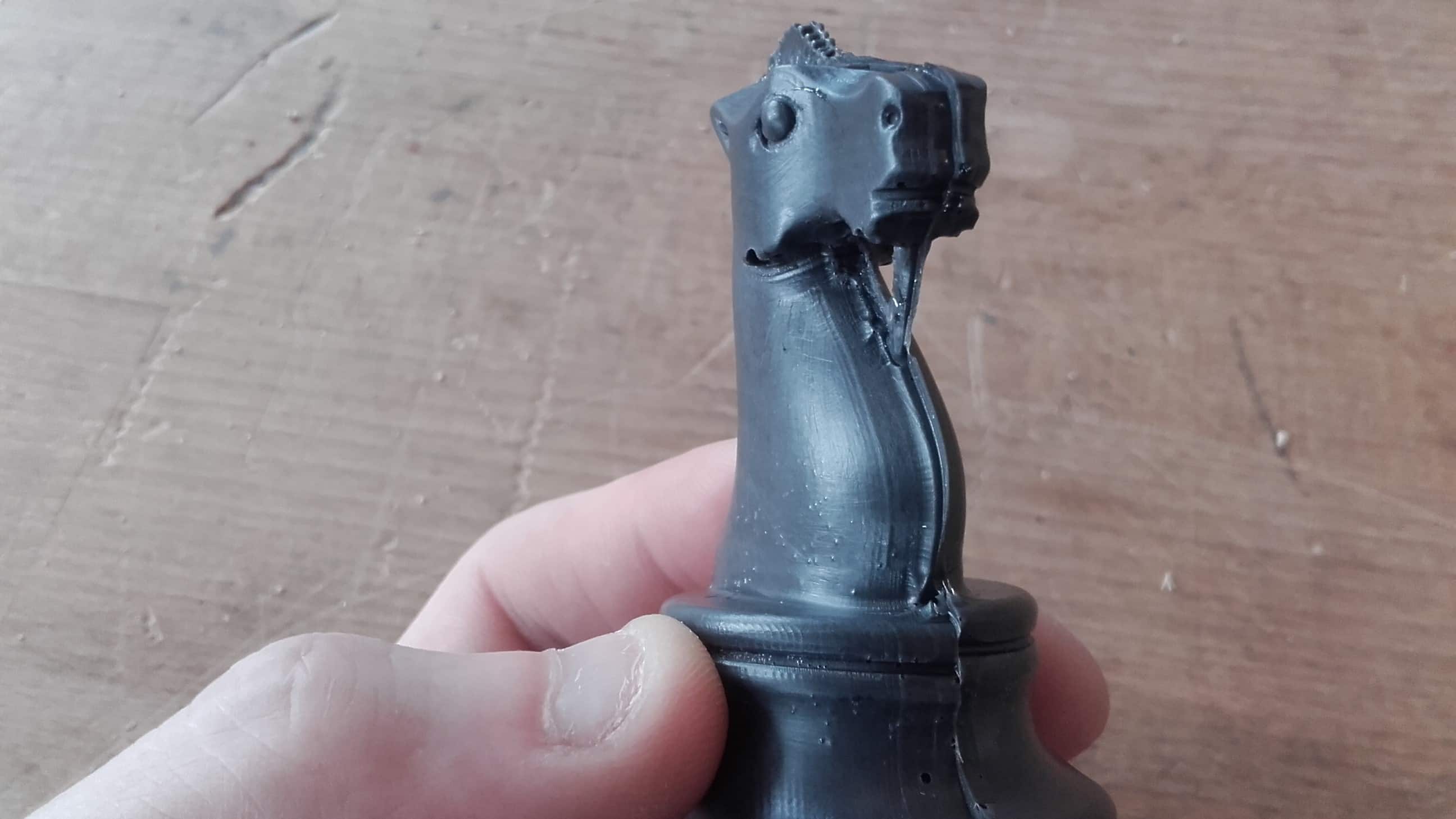
The resin did flow into all of the parts of the mold so I think the casting was a success despite the slight misalignment.
Final Result
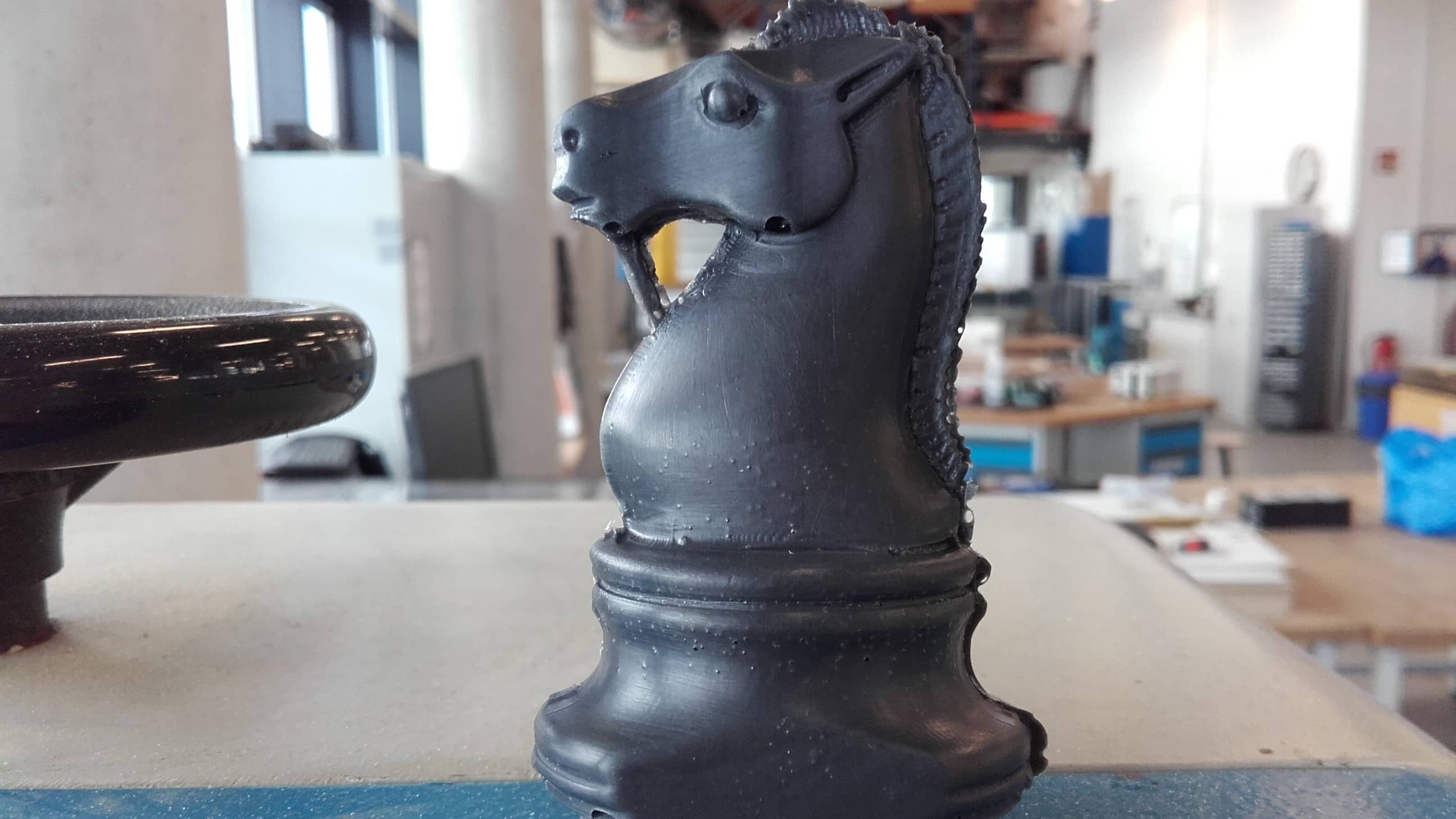
And I think the final result came out looking pretty good as well.