Applications and Implications
Concept Questions
What Will It Do?
Description
Who's Done What Beforehand?
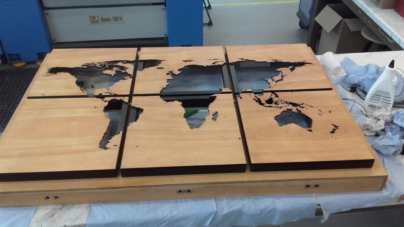
CNC Milled World Map
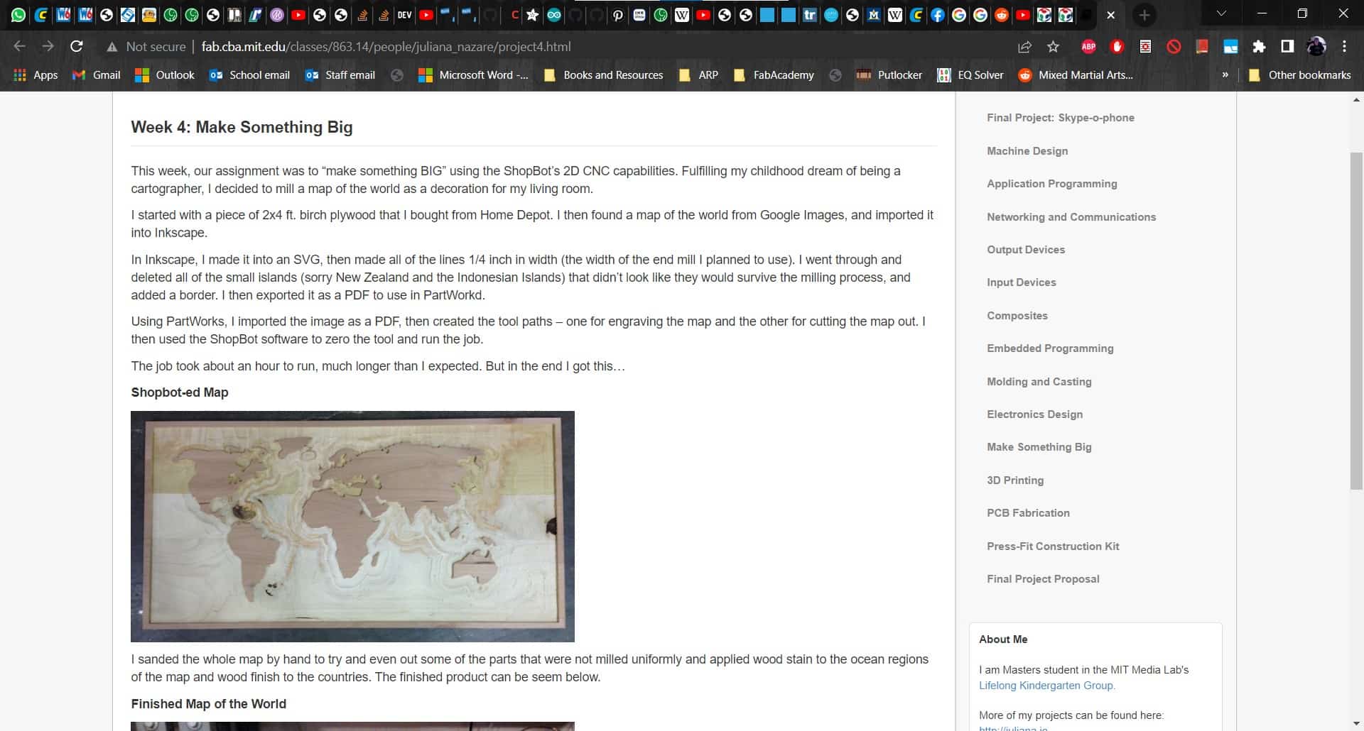
Juliana Nazare made a world map on a ShopBot for her something big project. I used the something big project for making the frame for my world map, but unlike mine, Juliana's project was not interactive at all, nor did it contain any electronics.
Capacitive Touch Map with GUI
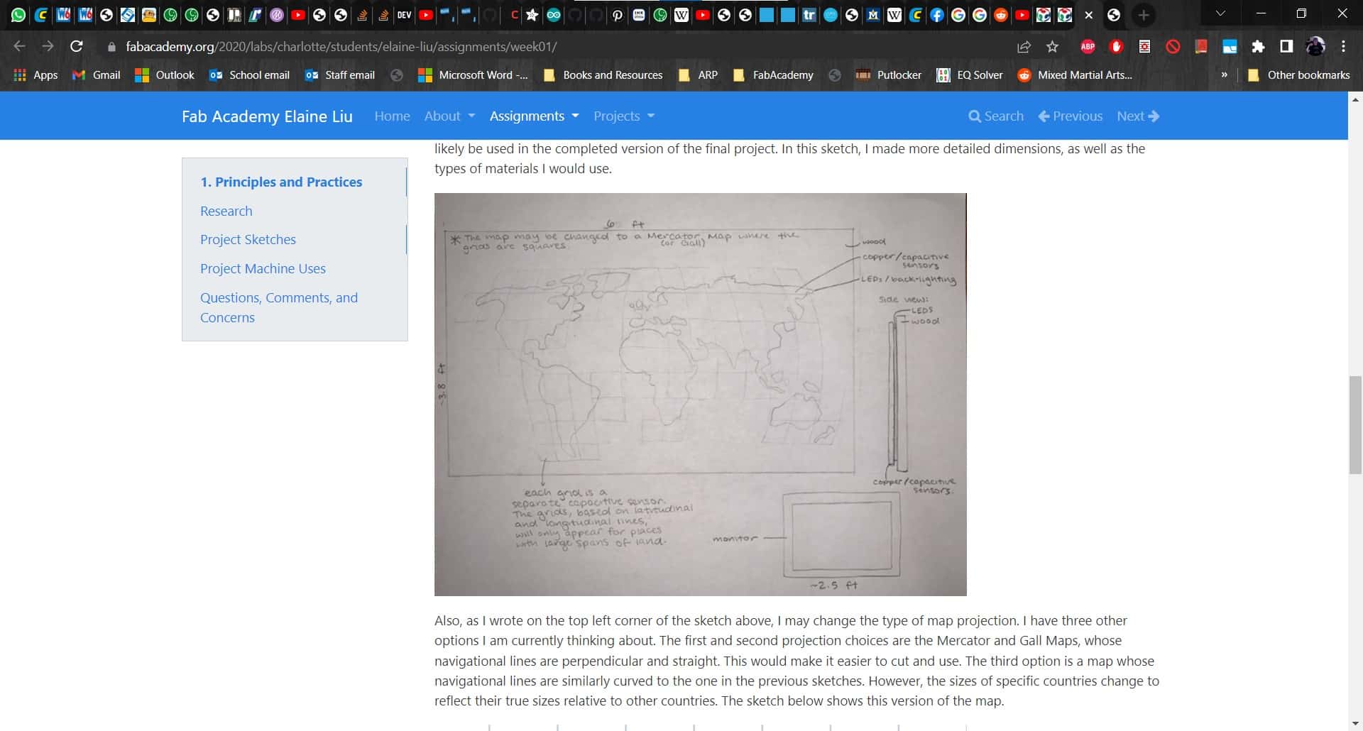
Elaine Liu made an interactive world map for her final project. This was an interesting idea to use capacitive touch to interact with the continents and pull up information about them on a GUI. Her project is much smaller than mine, and more interactive. Mine is more a piece of artwork that also provides ambient lighting.
Educational Arab World Map
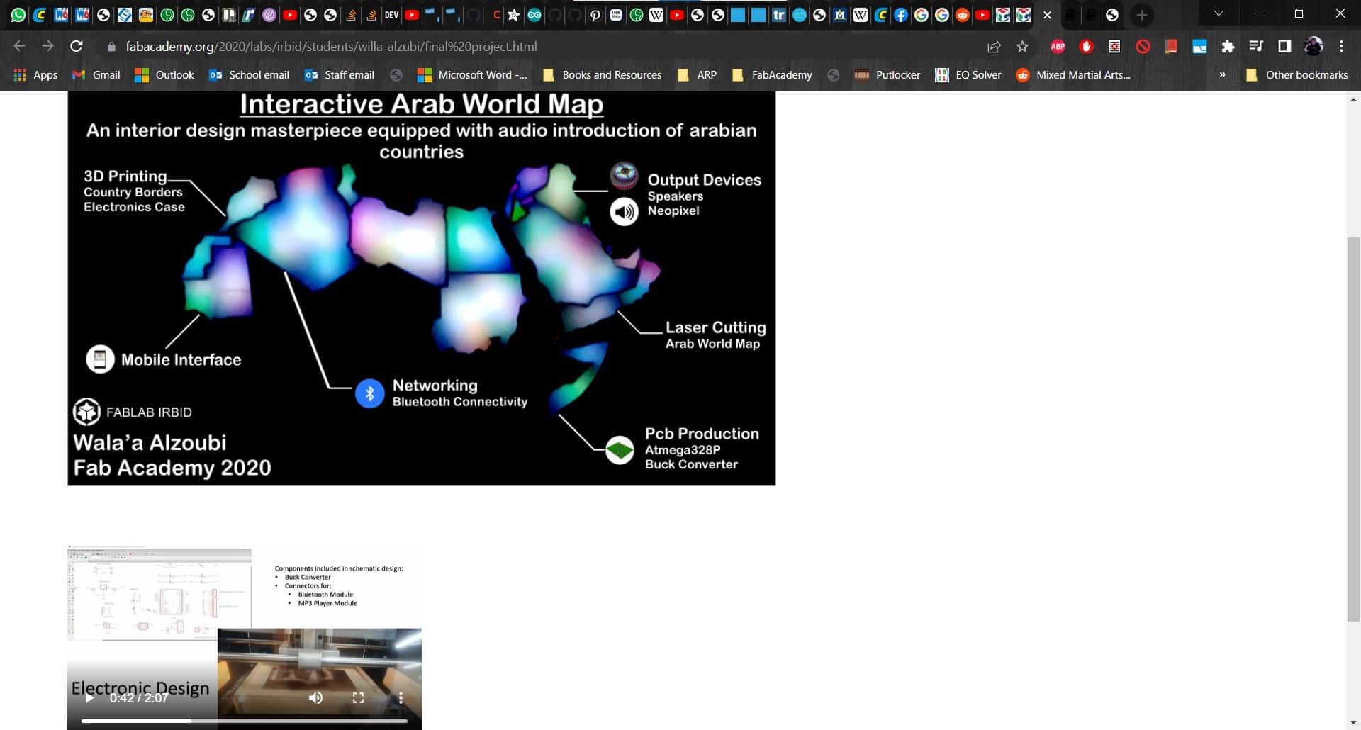
Willa Alzubi also did a final project involving a map. This was a very nice project showing the Arabic countries. The map lights up and presents information about each country. This seems like it could be a useful educational tool.
What Will I Design?
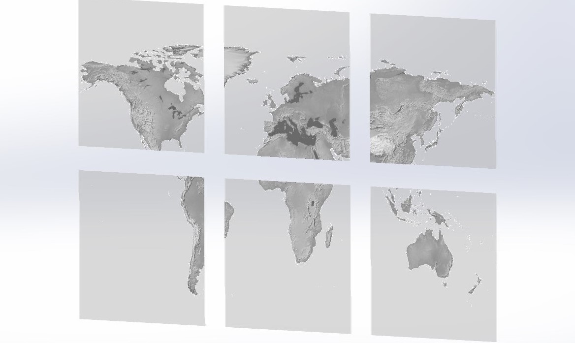
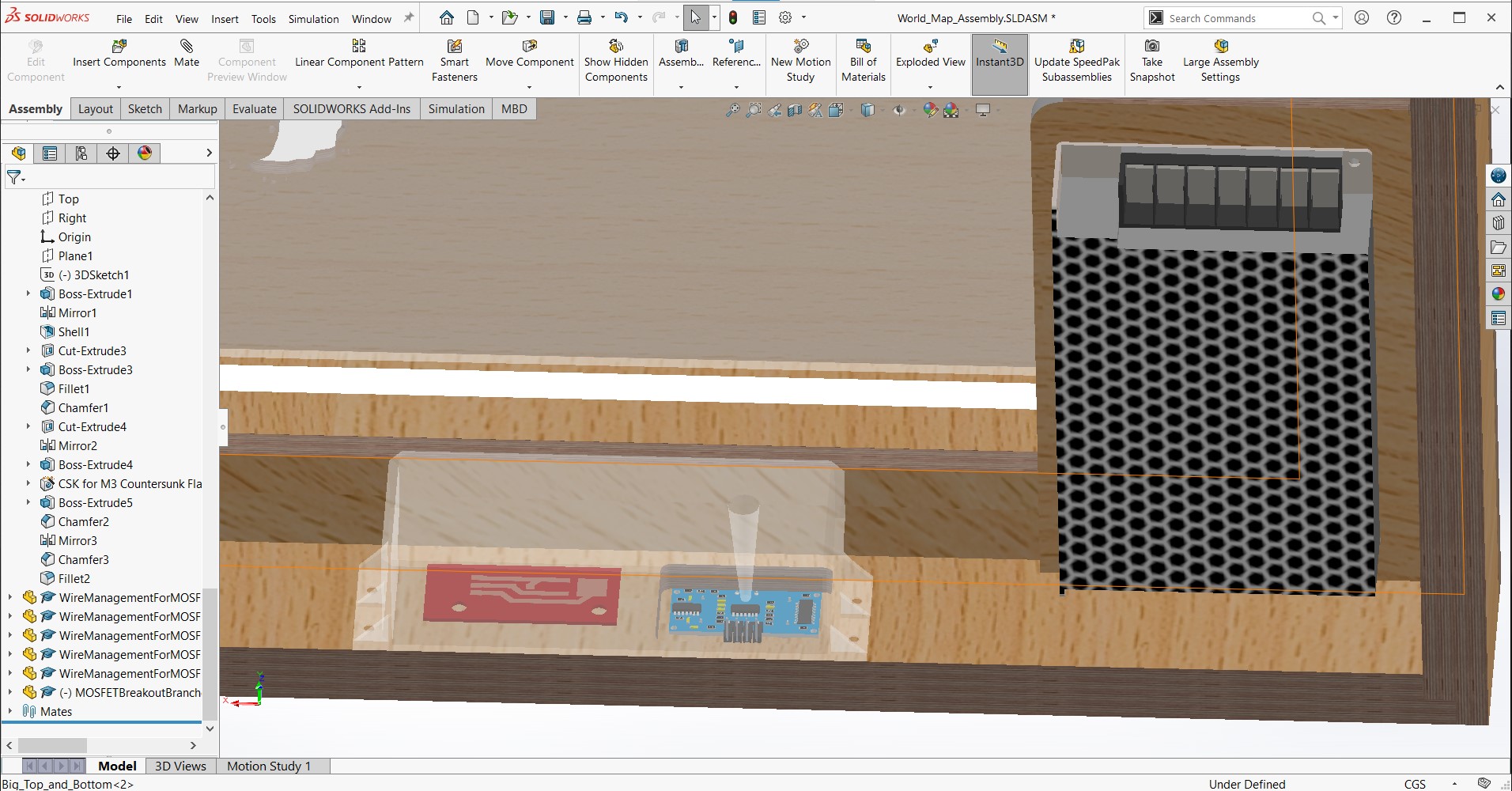
CAD
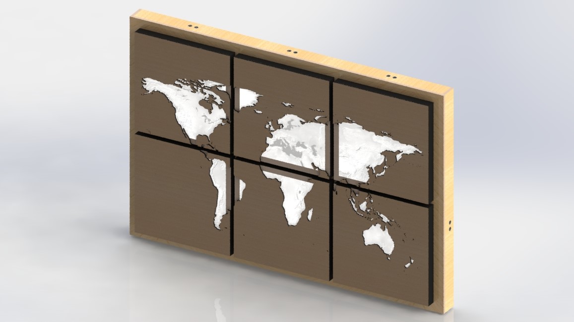
The CAD model will be made in SolidWorks 2021 Student Edition. Once complete, it will also be the source of any digital renders of the project. I will have to figure out how to make the individual parts and I will have to design based on the intended manufacturing technology.
Electronics
The design for the main board is not entirely my own. It is my own version, but the original Satshakit was created by Daniele Ingrassia. The rest of the electronics and the main circuitry will be designed from scratch. I will need to consider the voltage drop over different lengths of the wire I will be using to avoid different amounts of power going to different panels as well as how to create the full circuit with all of the electronics and components.
Embedded Microcontroller Interfacing and Programming
The ATMega 328P microcontroller will be interfaced with seven MOSFETs, seven ultrasonic sensors and six LED strips. The sensors will act as inputs and the LEDs will act as outputs. This world is new to me so I have a lot to learn. There are example sketches available for the individual components, but I will have to write the code that interfaces them with each other via the embedded microcontroller.
Wooden Panels
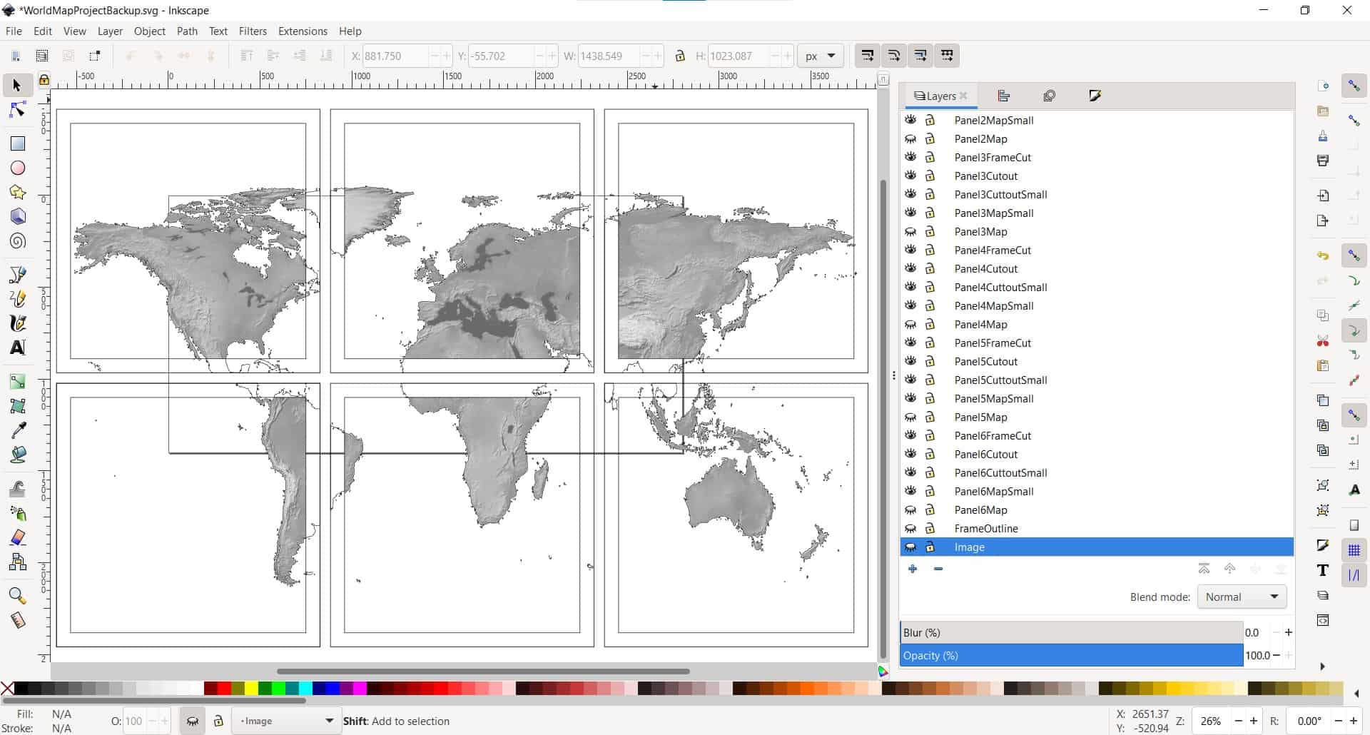
I will start with a source image. I will use Adobe Photoshop to clean up a few areas and to remove the background. Then in Inkscape, I will create vector layers for laser cutting the map silhouette onto the wood panels. I will have to figure out how to separate the layers of vector files into what I need. I will need to work on the map as a whole so I can maintain control over all of my panels at once.
Acrylic Panels
Also in Inkscape, I will create layers with inverted raster images for engraving the acrylic panels on the laser cutter. I need to figure out the optimal settings for laser engraving acrylic sheets. I also need to figure out how to engrave the high resolution images.
System Integration
The wire management and system integration will be designed from scratch. All cables will be properly routed and protected at every step of the design process. I will need to sort out what wires go where so I can design these parts to route and protect them. I need to find a good balance of print quality and print duration so as to avoid needing too much time to make the necessary parts.
What Materials and Components Will Be Used, and Where Will They Come From?
Bill of Materials: Make Parts
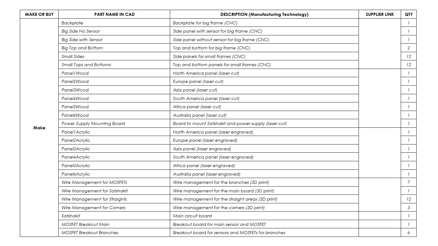
I decided to split the Bill of Materials into two parts: Make parts and Buy parts. The materials for the Make parts can be found under the Supplies heading in the table for the Buy parts.
Bill of Materials: Buy Parts
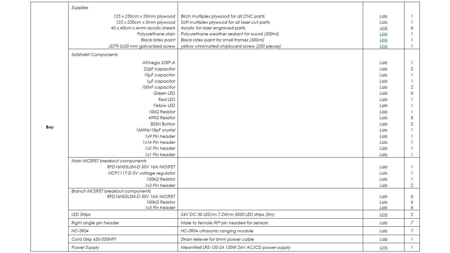
The suppliers for the Buy parts can also be found in the table. The components that came from the lab are clearly marked, and those that came from other suppliers have included links.
How Much Will They Cost?

The total cost for the project (not including the time investment) is approximately 391 euros. Most of that cost (about 245 euros) comes from the local prices of the lumber. The other bigger ticket items are the acrylic panels, the power supply and the LED strips. The rest of the components can easily be purchased for a few euros each. This project could be made less expensively and with less total weight in the end, if thinner plywood was used for the frame.
What Parts and Systems Will Be Made?
Frame
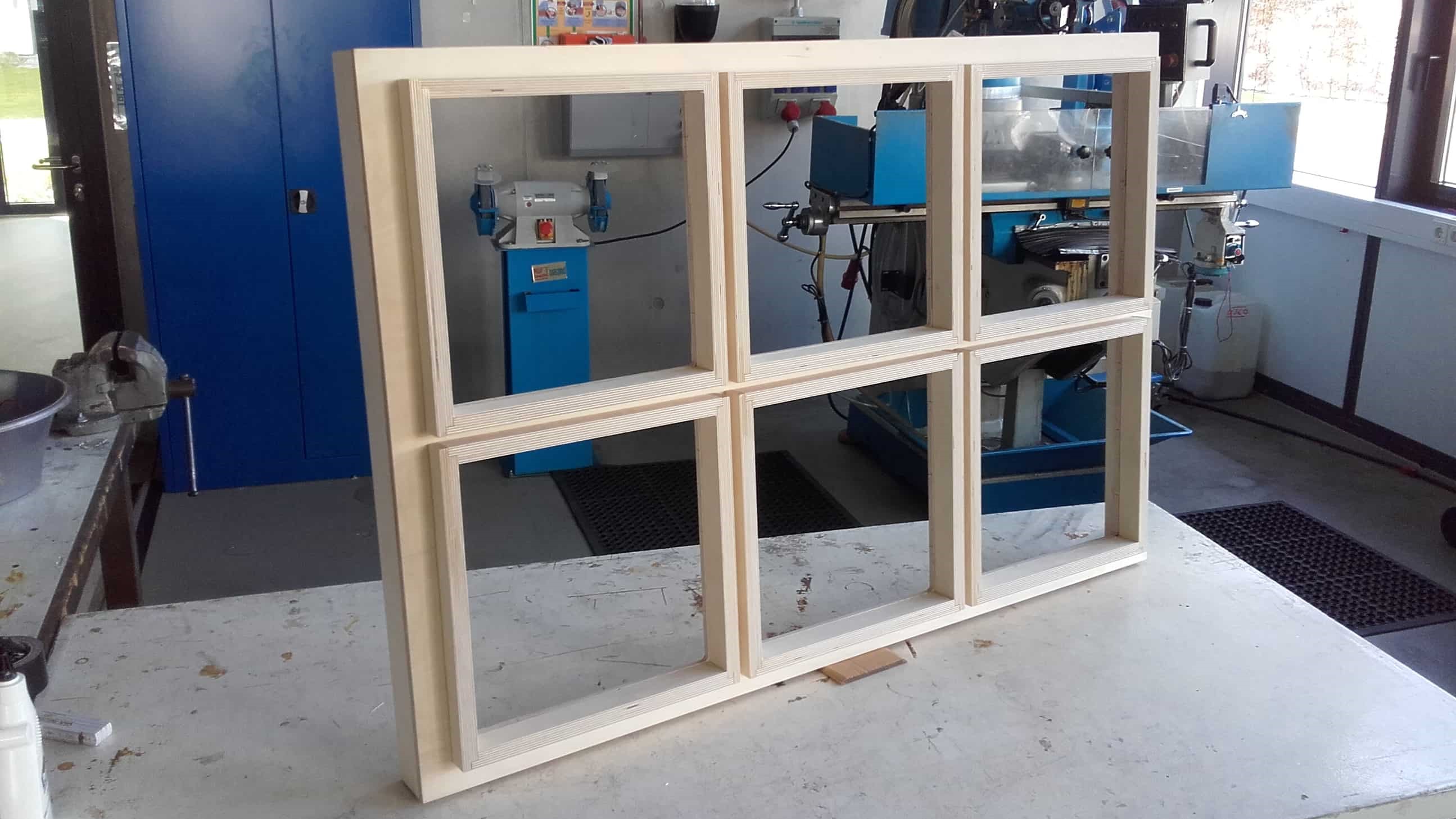
I will build the physical frame using plywood parts cut using 2D milling operations on the CNC machine. The CAM will be made in Fusion 360. The parts will fit together with no visible dog-bones and no visible seams when viewed from the front. I will need to figure out how to clean up the parts after milling, and I need to work out a proper order of assembly so everything fits together.
Wooden Panels
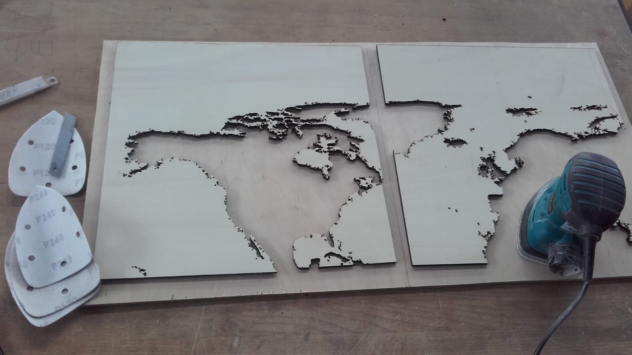
I will also build the wooden panels. From Inkscape, I will open them in Visicut to create the laser cutting gcode, and then I will use UGS Platform to stream it to the Fabulaser Mini. I will have to figure out what speed and power are ideal for laser cutting my plywood. I need a complete cut since many of the map feature are fragile and may break while trying to separate uncut "tabs", but I also need to avoid burning and excessive smoke, and of course, time is a factor. I need to figure out how to cut these panels without monopolizing the laser cutter for an entire week.
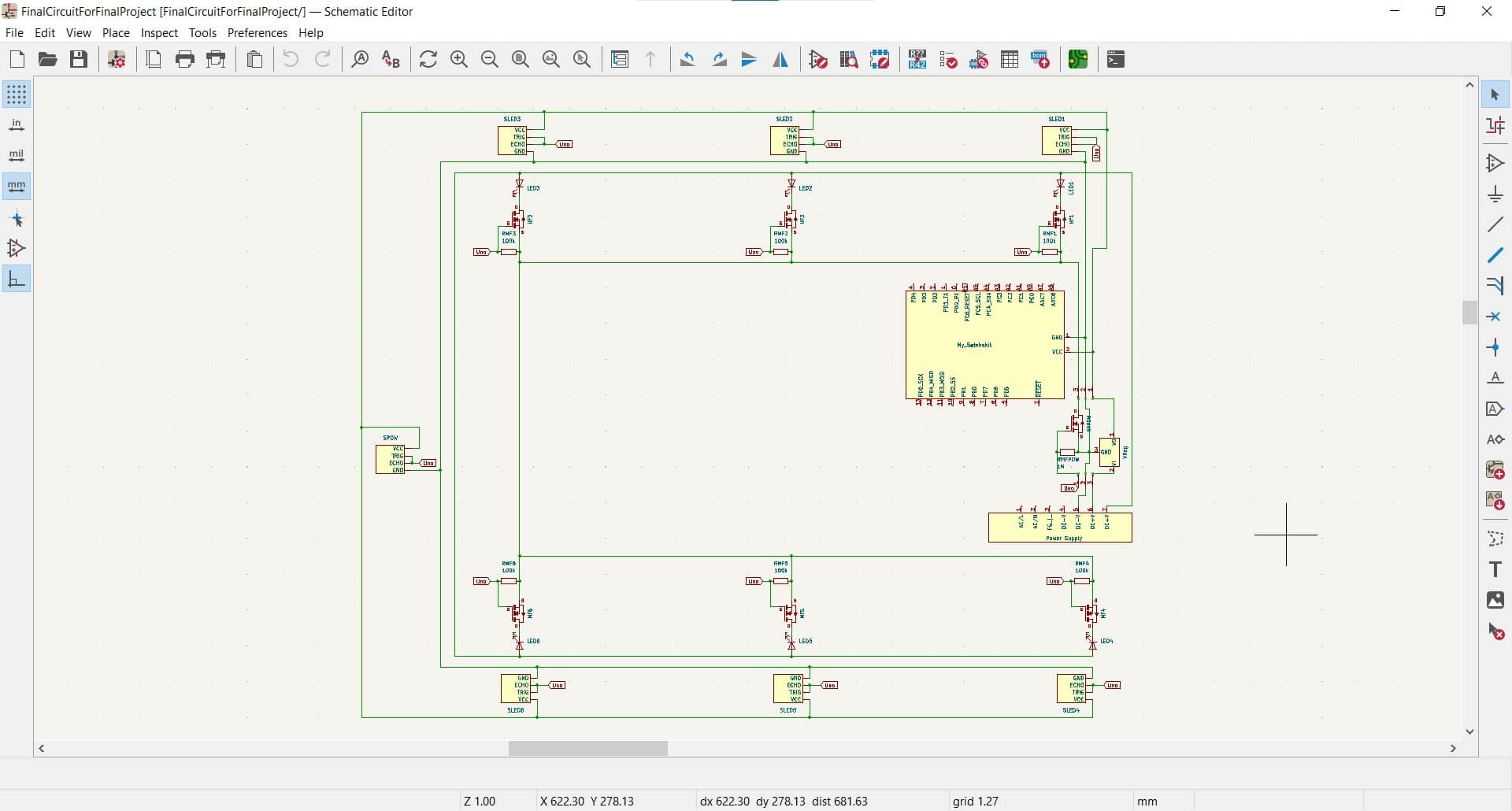
Main Board
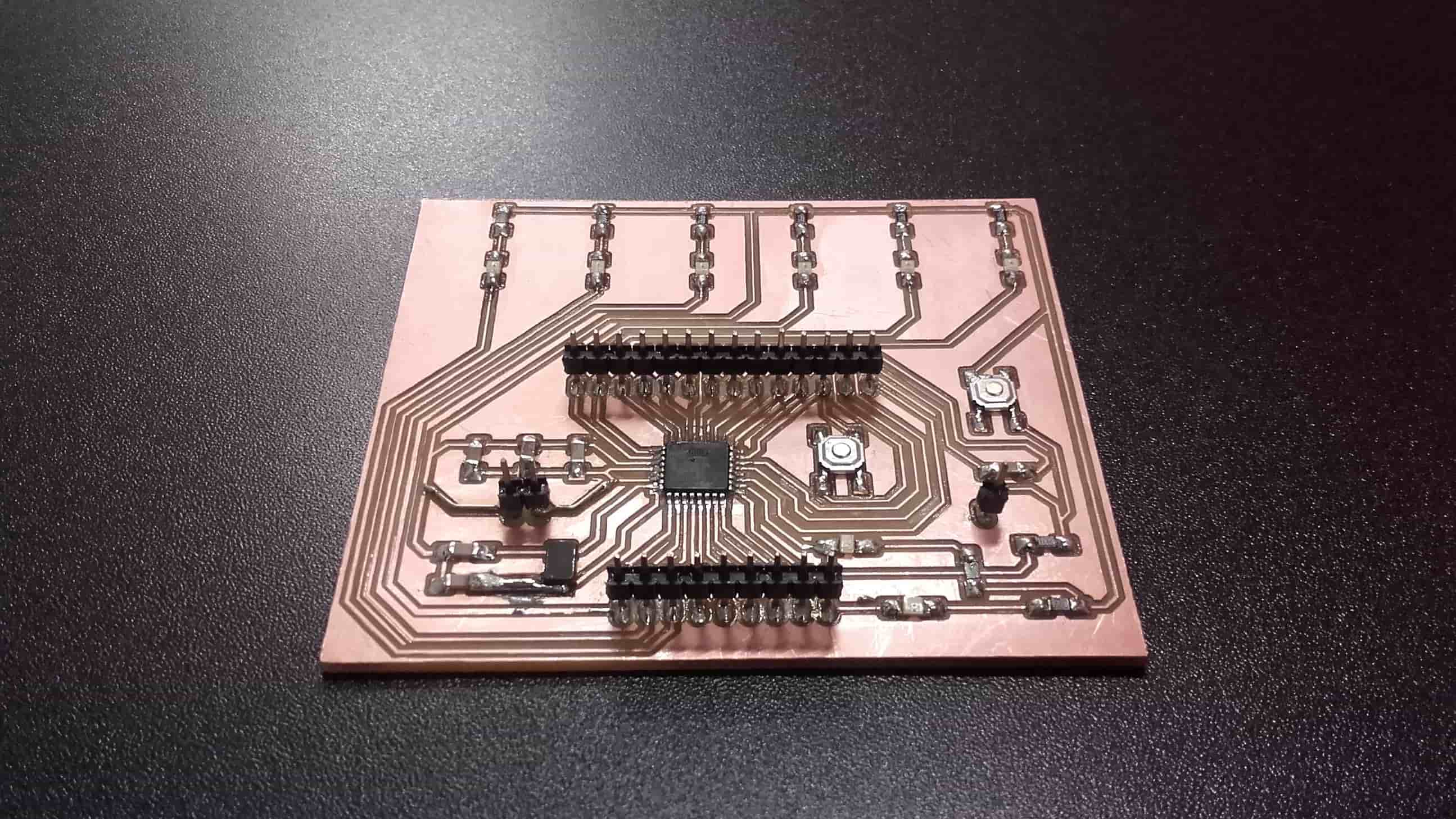
I will make a version of the Satshakit to serve as my main board for this project. The schematic and blueprints will be designed in KiCAD; the gcode will be generated using MODS; the gcode will be streamed using Candle; and then the Genmitsu 3018-Pro will do all of the PCB milling. I will have to figure out how to route my version of the Satshakit.
Breakout Boards for MOSFETs
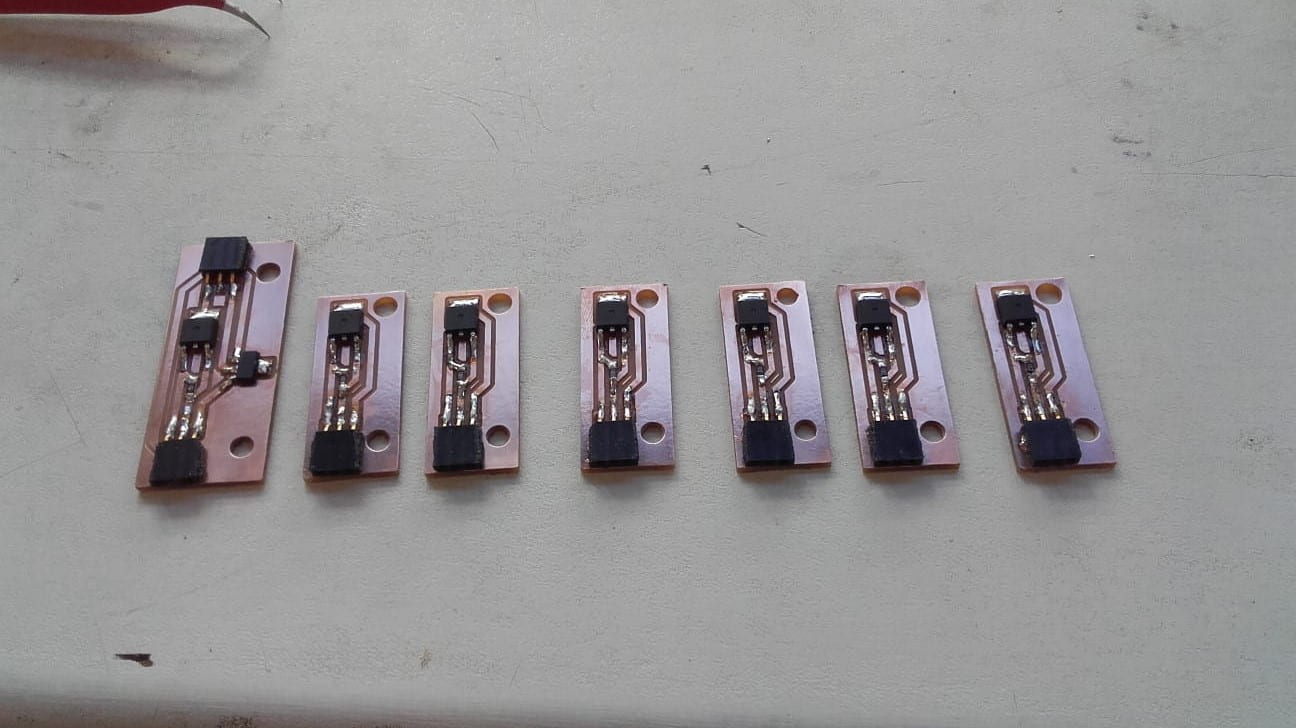
Once the milling is finished, I will clean and stuff the boards using SMD components that are available in the lab. The breakout boards will follow the same process as the main board, but I will make all seven of these boards simultaneously. I will have to make these boards to house the MOSFETs and their resistors and I will have to figure out how to connect all of the sensors and breakout boards with the main board and the power supply.
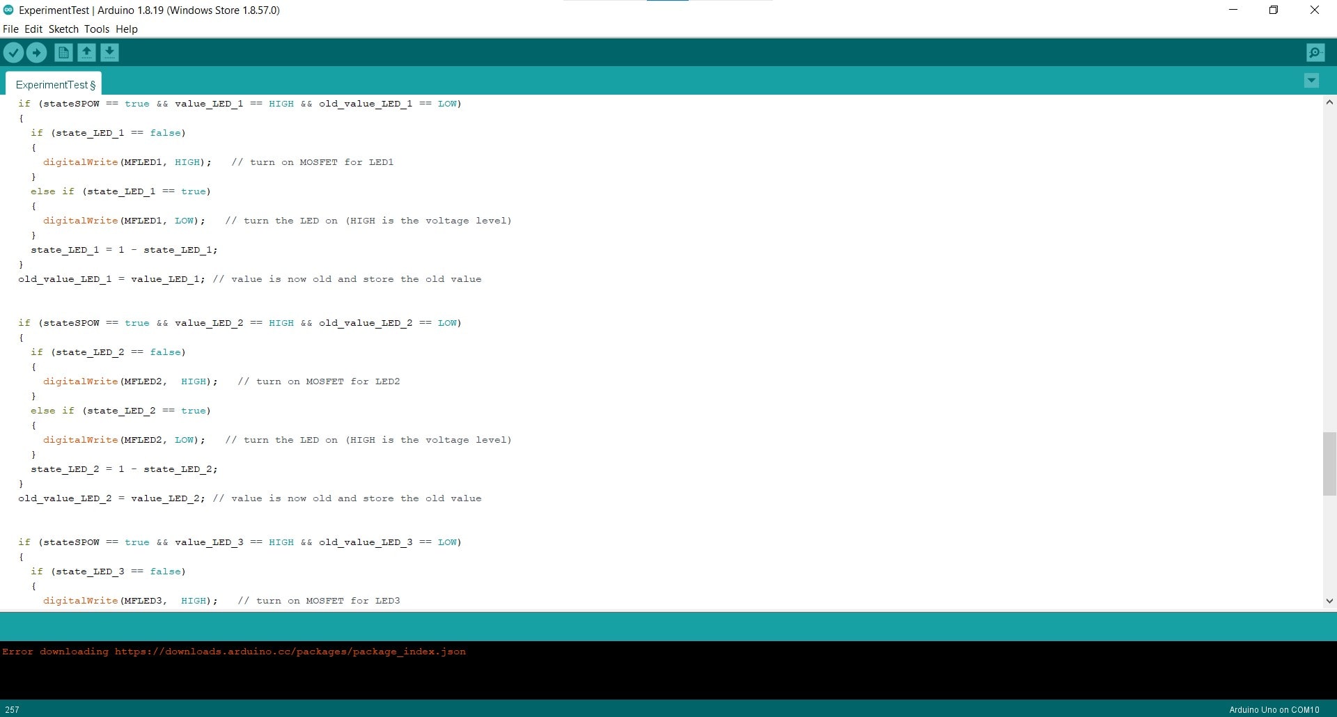
Code
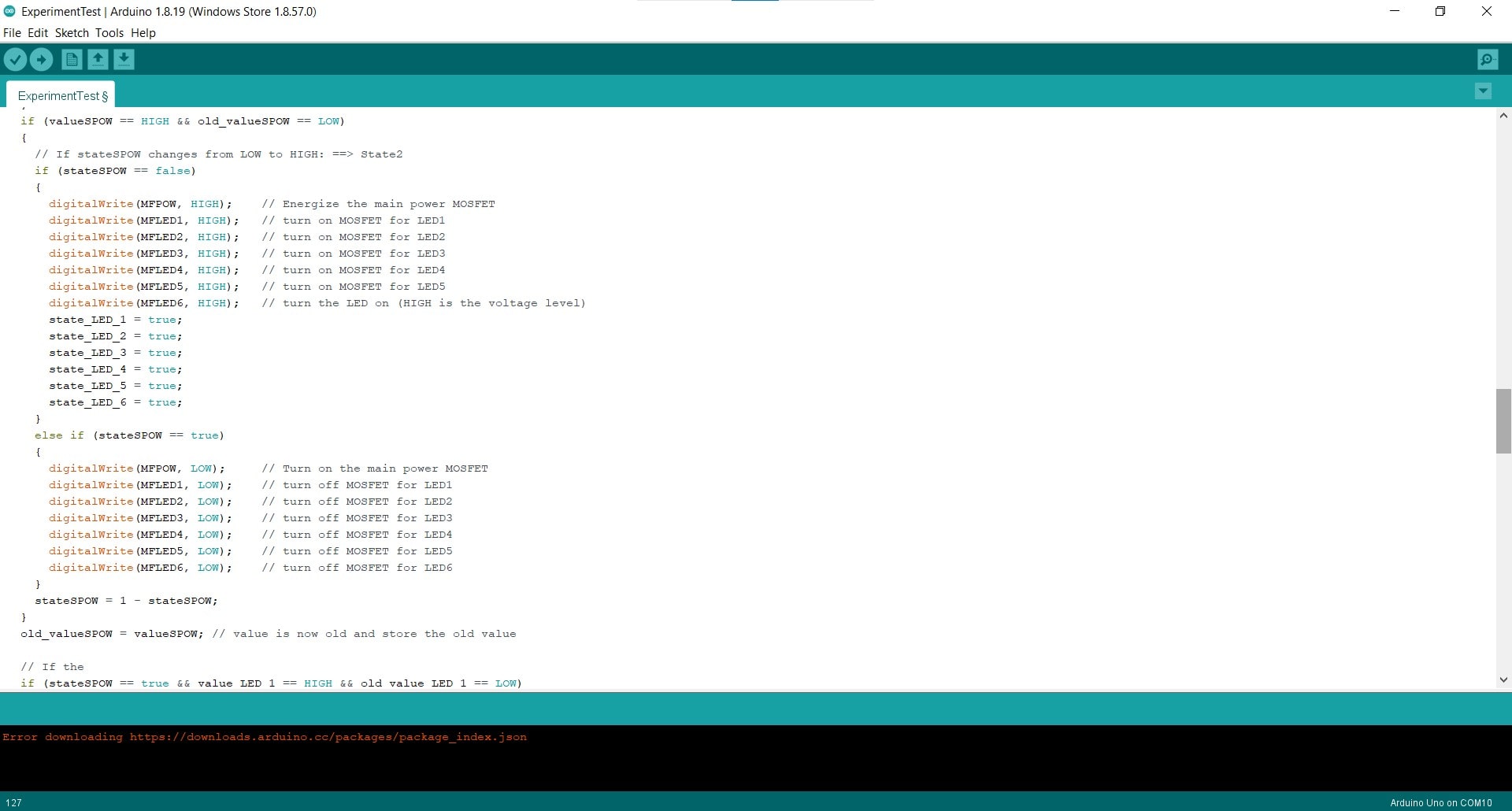
The code for the project will be written in C++ and will be implemented using the Arduino IDE. It will include snippets from various example sketches available in the IDE, but the rest will be written from scratch, exclusively for this project. I will have to figure out which pins on my main board will do what with my output devices. I will also need to make sure my code works before hooking everything up to the Satshakit since I will have to use some of the programming pins for the final configuration.
Finishing
All of the parts will be hand finished. Finishing will include sanding, cleaning, painting, staining, gluing and assembling all of the components of the frames, the panels and the electronics. I will have to figure out the proper toolchain and applications of elbow grease for finishing the piece in an aesthetically pleasing, artistic way. I will need to overcome a bit of OCD lol.
Physical Circuit
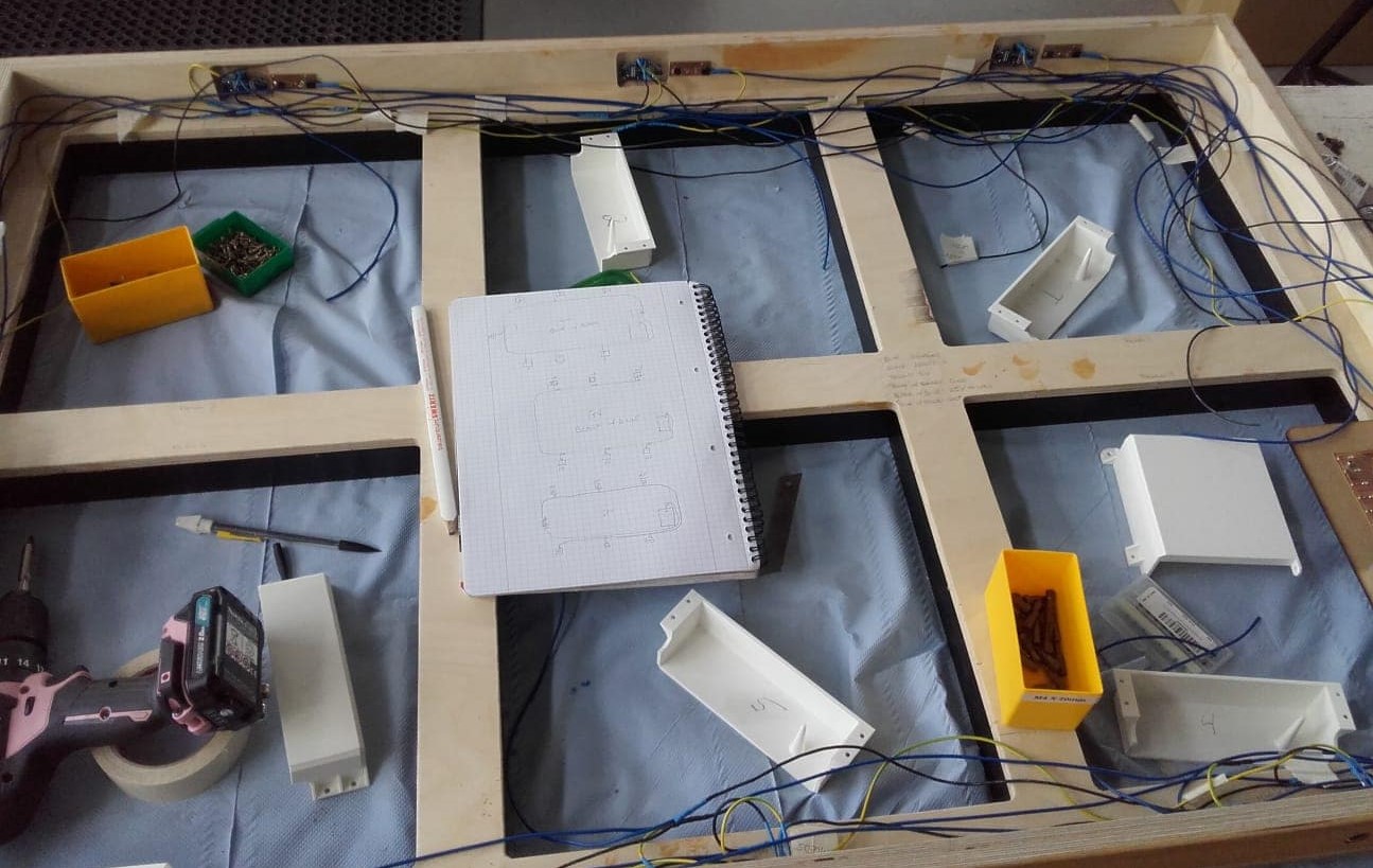
The circuit will be designed from scratch, specifically for this project. The physical placement of the components will determine the routing of the wires, but the design will allow for plenty of room for the electronics to be mounted discretely and connected safely.
System Integration and Packaging
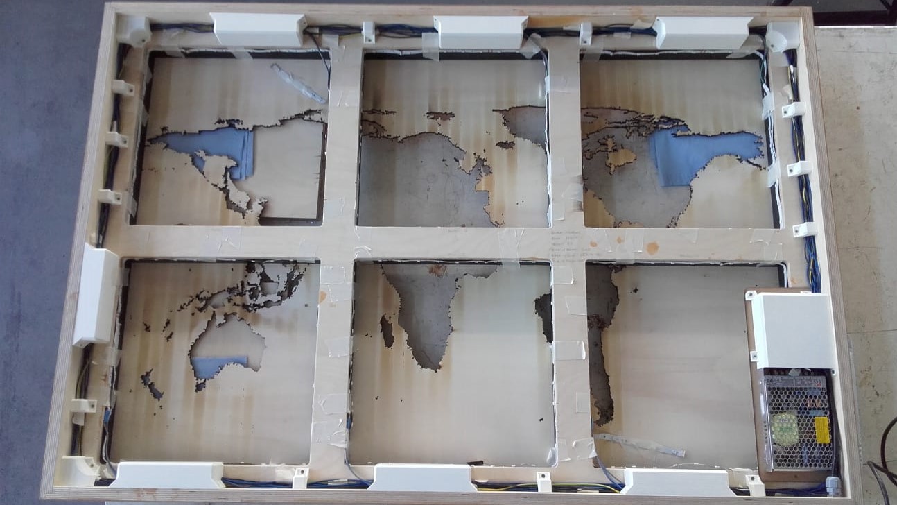
All cables will be properly routed and protected, and all permanent connections will be soldered. Strain relief for the power cable will also be necessary.
How Will It Be Evaluated?
According to academy.cba.mit.edu, the documentation for the final project should answer:
It also says the final project should integrate the range of units covered, and incorporate: