Output Devices
Hero Shots
Click Here for Our Group Assignment
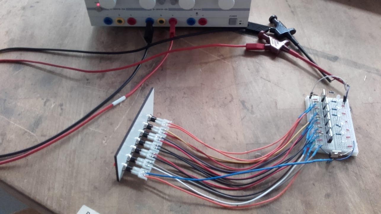
Full Circuit with Sensors Activating LED Strips
File Downloads From This Week
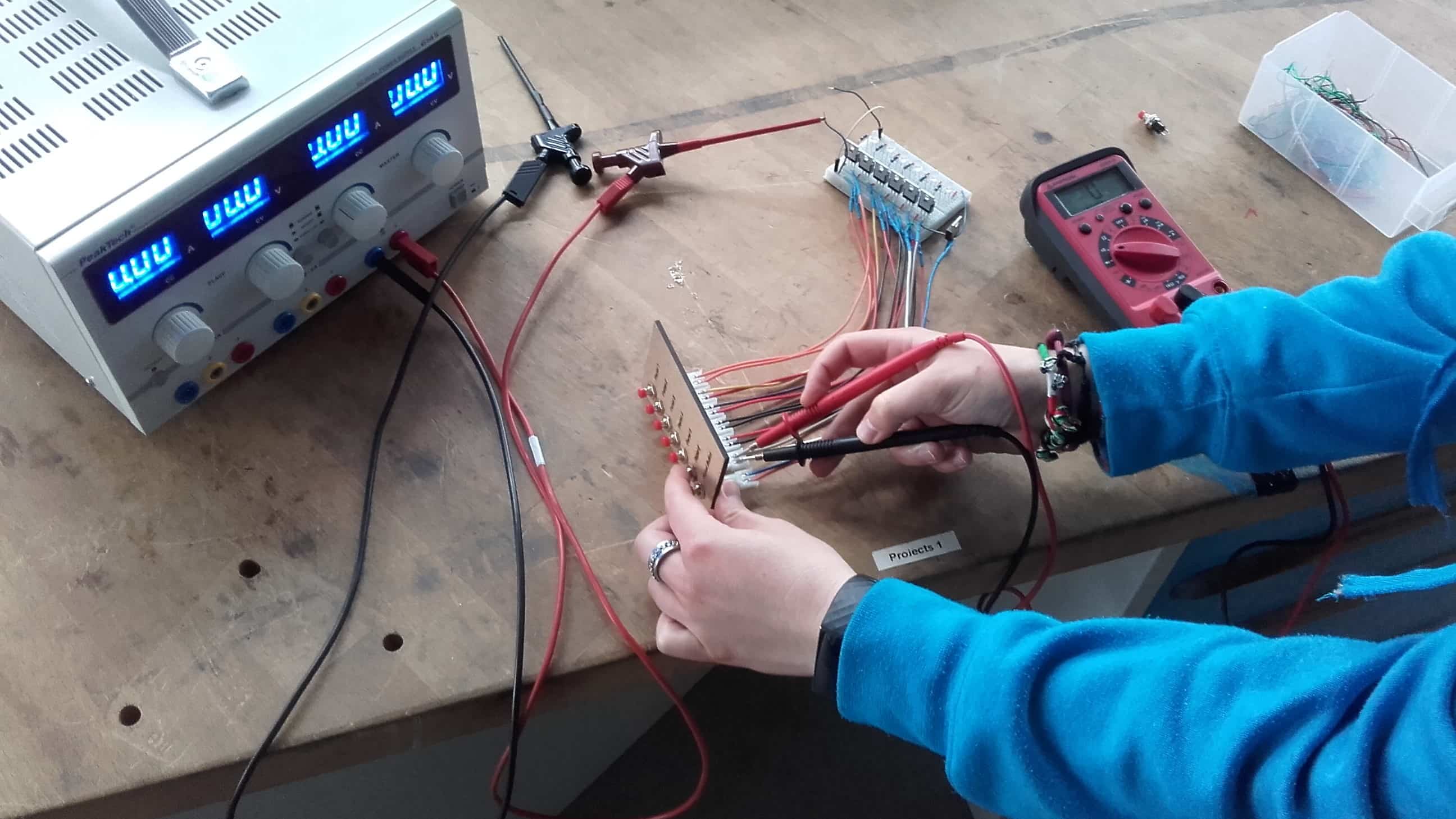
Video of Physical Circuit
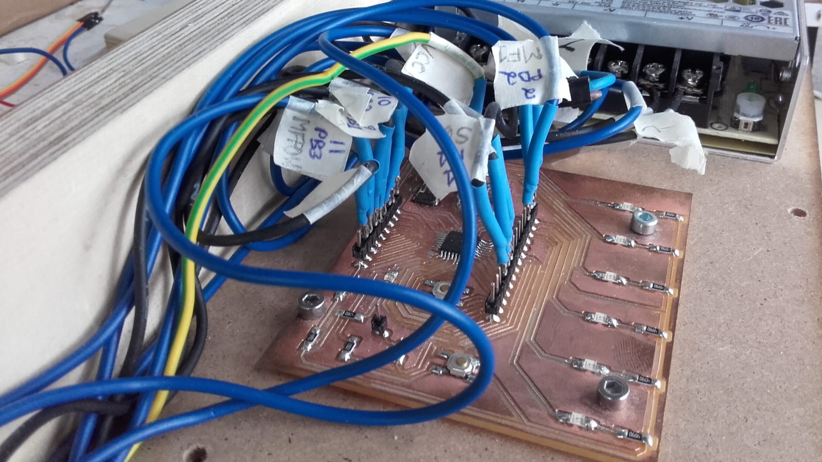
Everything Connected to the Satshakit
Initial Reaction
Oh man! The week has just begun and I am already feeling overwhelmed. Once again, I feel like somewhere along the lines, I missed the classes on practical electronics. I have heard the theory so many times I feel like I can recite it, but I have never been taught how to use any of it. Are some people just born understanding electronics and how to get them to do what you want? When are the rest of us meant to learn it? As usual, Neil did a wonderful job describing and explaining the available options. My failure to understand the topic is certainly not a result of his instruction...if anything, more instruction is exactly what I need. Our assignment this week is to use the board we made to interface with some outputting peripheral and to make it do something. I am definitely going for the low hanging fruit this week. If I can get my LEDs to turn on when I want them to, then I will be very pleased with myself. Extra credit be damned lol.
After Local Workshop
Once again, I am feeling a little better after the local workshop. I still have no idea what I am doing haha, but at least now I understand that I don't need to understand everything. This week, Marcello walked us through several of the most popular output components as well as how to implement them and then showed us some FabAcademy examples of each. I'm still not really sure where to start with my own project, but at least I have a pretty good idea of which components I will need to include in the final circuit. Even though I am scared and overwhelmed, I am still looking forward to this week. I REALLY need to learn this stuff...and I'm not likely to encounter a better opportunity than FabAcademy. Here goes nothing! 😬
Selecting Components
Research
All Kits?

Lacking a better plan, I started by simply googling "LED chains" to see what I could learn. I know I need six 1.5 m lengths of LEDs in the end, but I guessed it would be cheaper to buy 9 or 10 meters all at once. I also knew that I want color LEDs, and even though I only want them to turn on and off for now, it might be nice to have other options for controlling them if later spirals take me in that direction. I started struggling right away. Everything I could find on Amazon seems much more complicated than I want. These are all kits that come with controllers, remote controls and power supplies. I am looking for components.
5050 Series
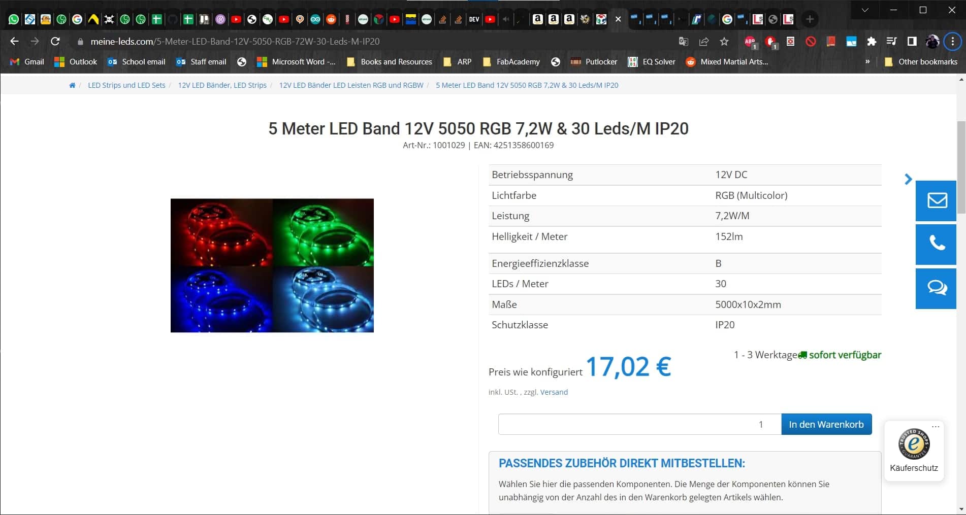
After a bit of searching, I discovered that what I am looking for are called LED strips, not chains, and that colored LEDs are called RGB (this seems so dumb to write, but I didn't know before this, so whatever). I was originally thinking about going with 12 Volts since that's the approximate size of the components we had looked at in the workshops, and the cheaper IP20 LEDs were looking good since mine will be indoors and I have no need for waterproofing them. Getting this far also allowed me to choose 5050 series LEDs and to start getting into the datasheet for those.
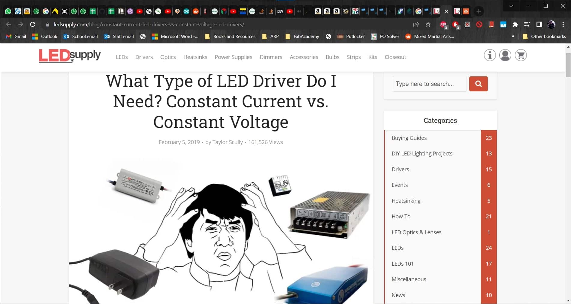
Weighing Pros and Cons
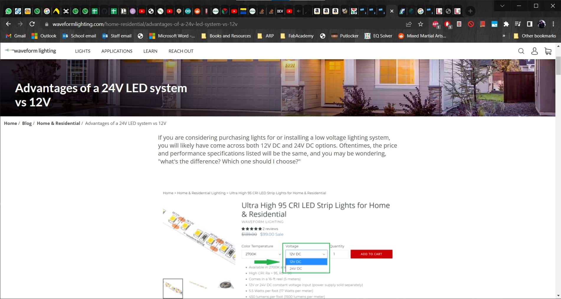
After some more searching, I discovered a very useful article talking about the advantages of using 24 Volts over 12 for systems like mine. These advantages include better efficiency and lower operating currents, which allow for smaller power supplies.
24 Volts
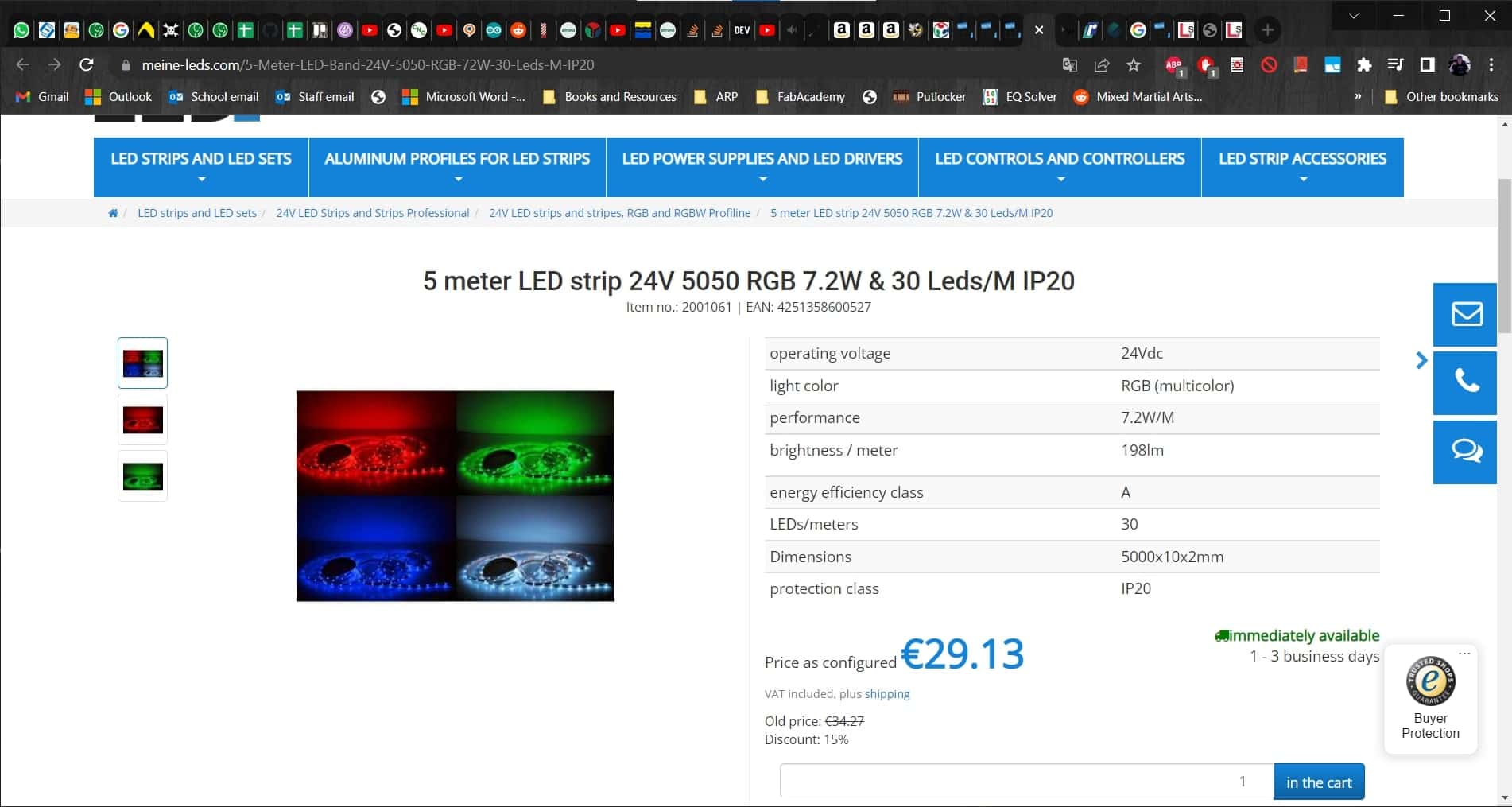
The downside of 24 Volt LED strips is that they can only be cut every seven LEDs (the length of a "string"), rather than every three LEDs for 12 Volt systems. Since the LEDs will be hidden, I don't mind a bit of a gap or overlap in this design, and the 24 Volt strips seem like a better option now.
Power Supply

Once I had chosen the LED strips I want to use, I needed to find a power supply. I know the LED strips are 7.2 W/m, so that should mean that each branch will consume 10.8 W and all six branches in parallel should consume 64.8 W. This guide and this article got me started on understanding the relevant parameters...
How to Choose?
...and this guide gave more in depth information. Using them in combination with this basic electronics tutorial, I was able to sort out what kind of power supply I will need. I only need 86 Watts to meet the "120% rule" so at this point I was planning to get a 100 W driver.
How Many LEDs?
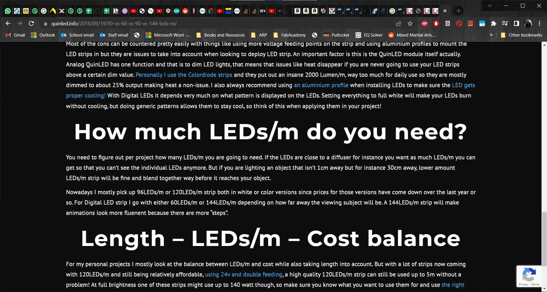
Finally, I wanted to double check the brightness since I have a choice of how many LEDs I want per meter of the light strip. According to this article, it all comes down to the price balance. For example, I would love to get the 60 LEDs/m version, but they are almost twice the price (big surprise). So, to make sure that 30 LEDs/m would at least be bright enough...
Bright Enough

...I found another article that gives relative comparisons. According to it, 200 lumens is "suitable for reading and more decorative accent lighting." Perfect! I am pretty sure we already have the mosfets and any fuses and resistors I will need in the lab so I should be good to go once these parts arrive. Knowing I would have 30 LEDs/m allowed me to do a final calculation for my total current. 30 LEDs/m * 1.5m = 45 LEDs/branch * 6 branches = 270 LEDs * 20mA/LED = 5.4A + 200mA drawn by my Satshakit = 5.6 Amps total. So, in the end I decided to go with a 156 W driver since it can do 6.5 Amps. There was also one with 6 A, but it was more expensive than the larger one.
Making My Circuit
Button Panel
Panel Design in Inkscape
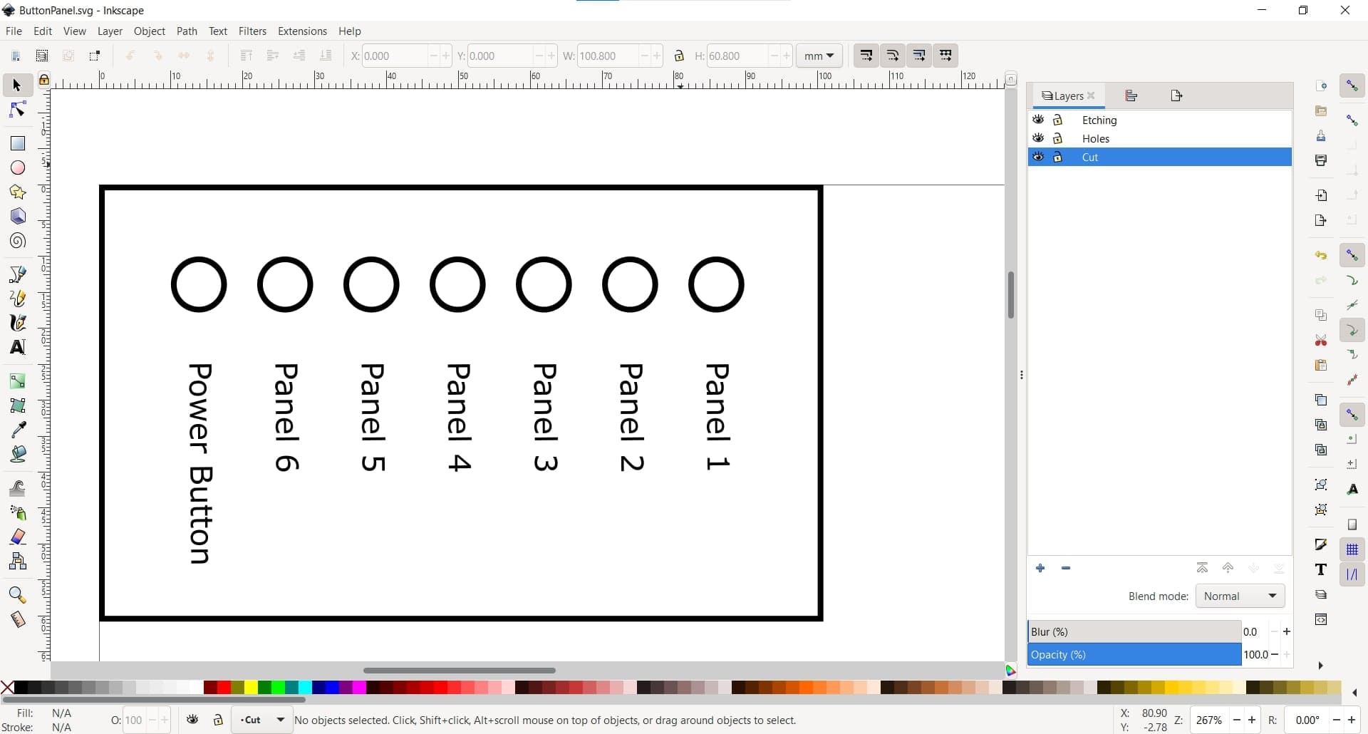
I knew I would have a lot of wires, and I wanted to avoid having a tangled bird's nest for a circuit, so I started by quickly making a panel to hold all of my buttons in place. I designed the panel in Inkscape...
Generating G-code in VisiCut
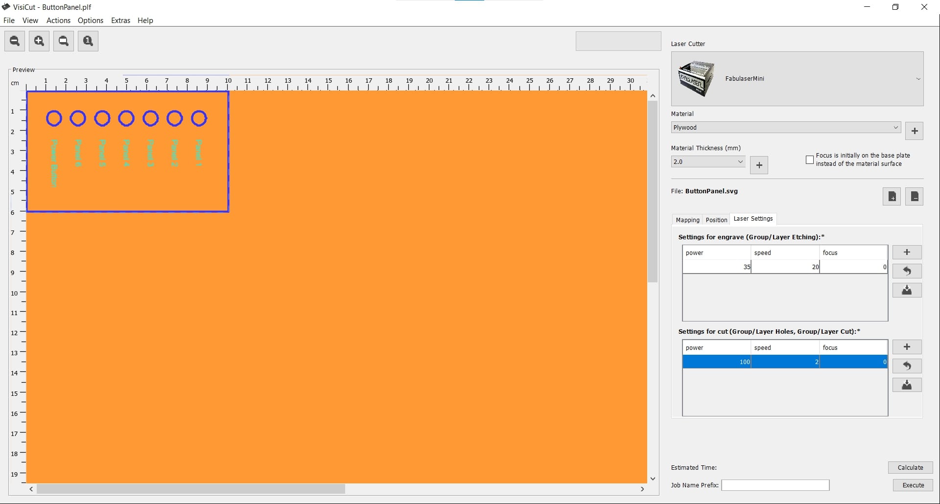 And then generated the g-code in VisiCut and cut it on our laser cutter using the UGS platform.
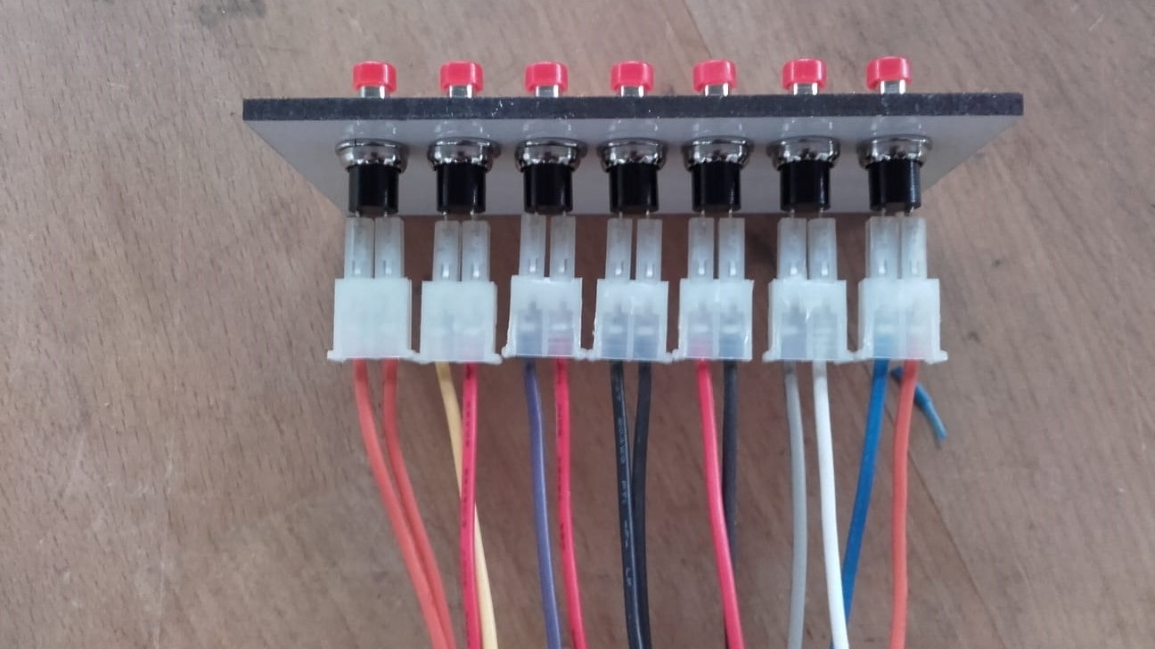
New Button Panel
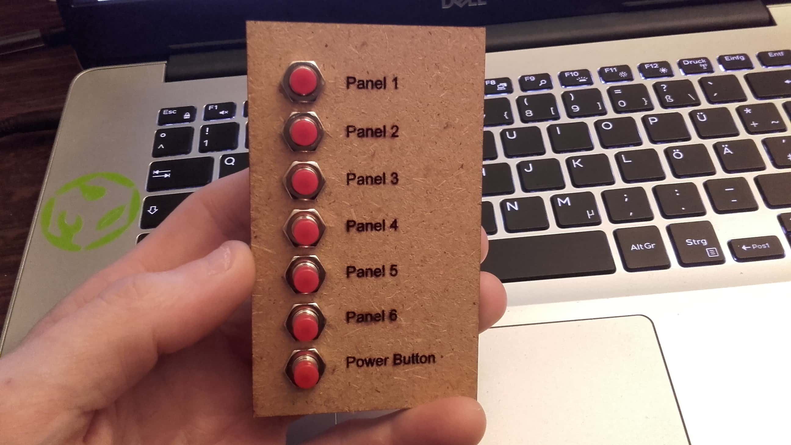
It came out pretty nice and I think it will help a lot.
Circuit Design
Pencil and Paper
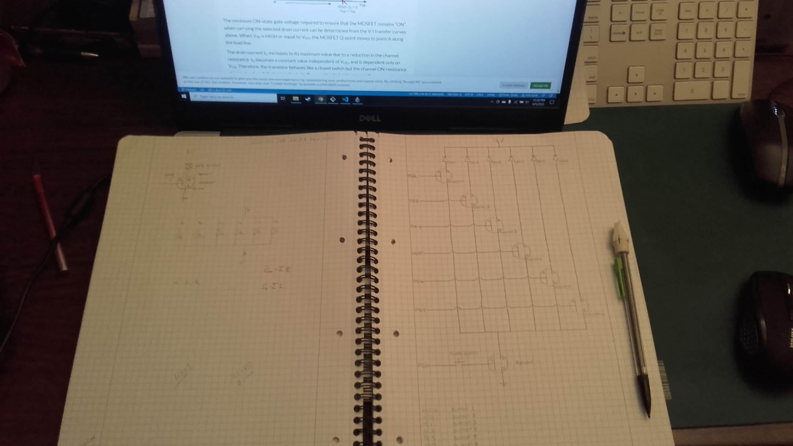
Trying to make sense of the circuit in my head wasn't working so I resorted to my trusty old tools, a notebook and a pencil. Once I worked out how I would connect everything, then I turned to an online simulator. Marcello had shared a few links so I chose one and got started.
Attempting to Simulate
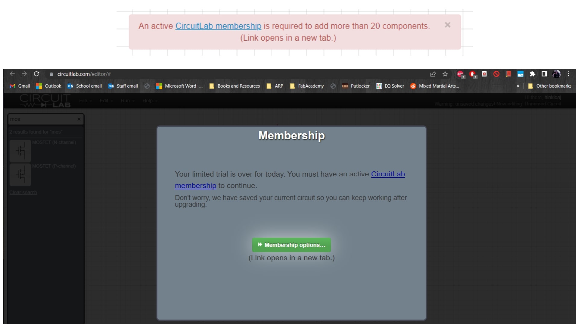
It was an online simulator called circuitlab.com with a free demo. The software was pretty intuitive and actually pleasant to work with, but I quickly ran into my first problem when I tried to add more than 20 components to my circuit; that's not allowed for free. So I decided to just model a few of the branches instead of all six. After all, I was just looking for proof of concept here to justify actually building the circuit physically. I kept plugging away until I was hit with the next problem.
CircuitLab Sucks!
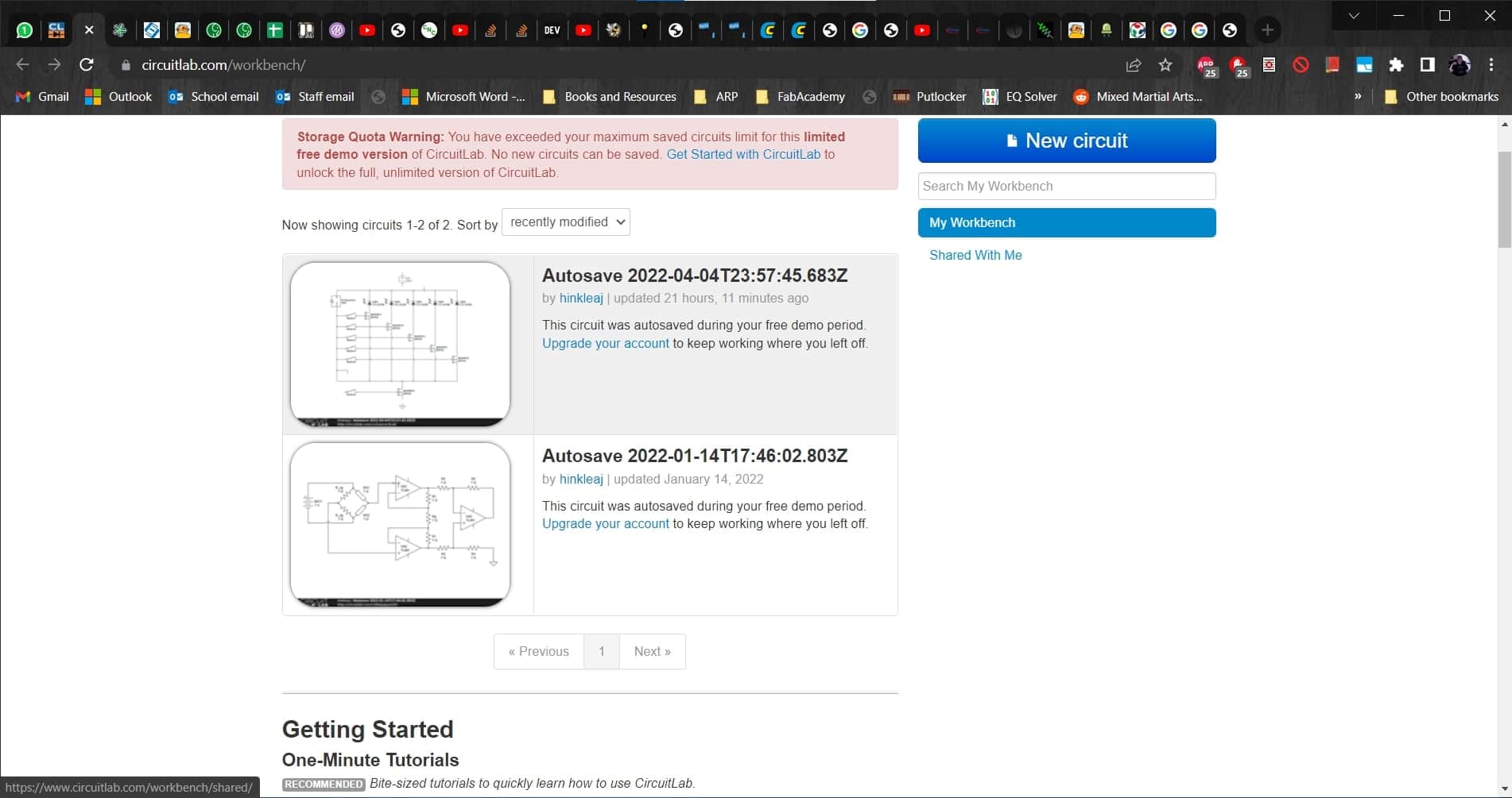
Apparently this free demo had some kind of unspoken time limit and when I reached it, I could no longer even view my circuit, let alone work on it. I despise these kinds of marketing tactics so I will never use CircuitLab again and I will warn others against it as well. 🖕
Falstad FTW
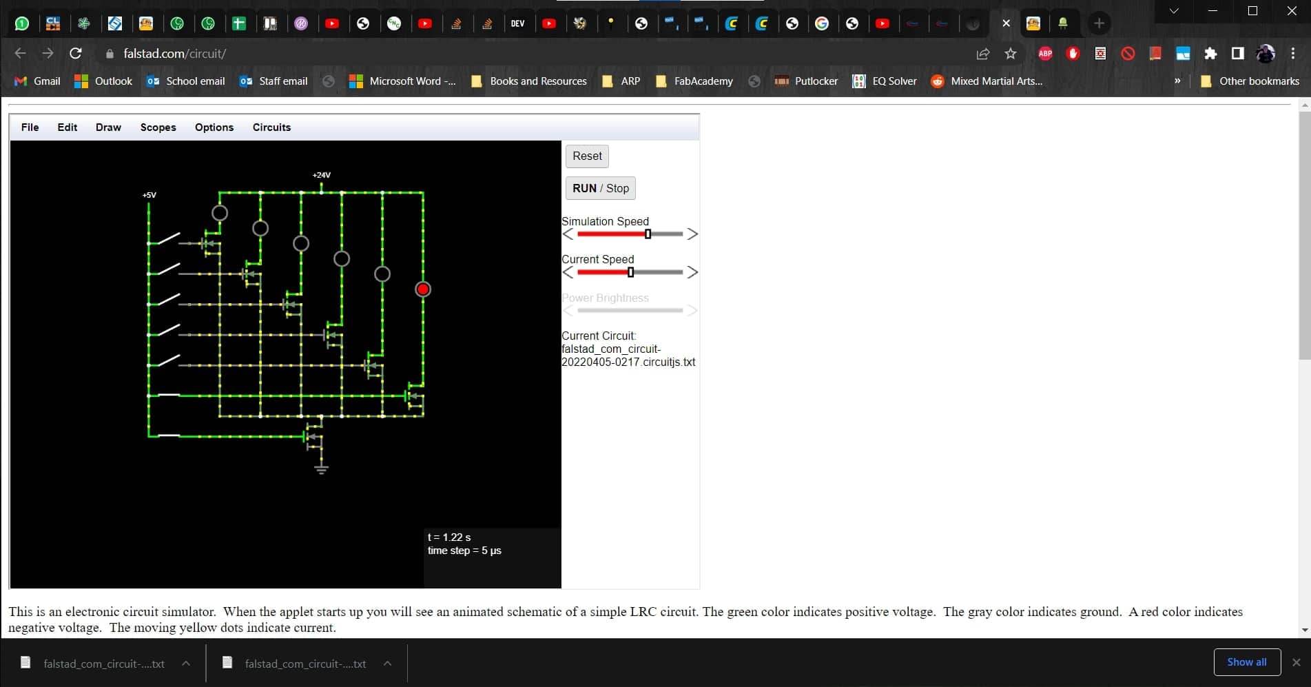
Not excited about having wasted hours on the previous simulator, I begrudgingly opened up the next link to see if it was any better. I went to falstad.com and started building my circuit once again. The software was good, and it even allows you to save and open project files. I am a big fan, but my circuit wasn't working as expected.
Not Working
For some reason, my circuit was getting power, even with all of the buttons open. This seriously confused me. MOSFETs are completely new to me so I assumed that I had misunderstood their function. I found a helpful article about using them as switches in circuits and another article about using them with Arduinos. I didn't understand every detail, but everything seemed to be confirming that I was using them correctly.
Active Switches
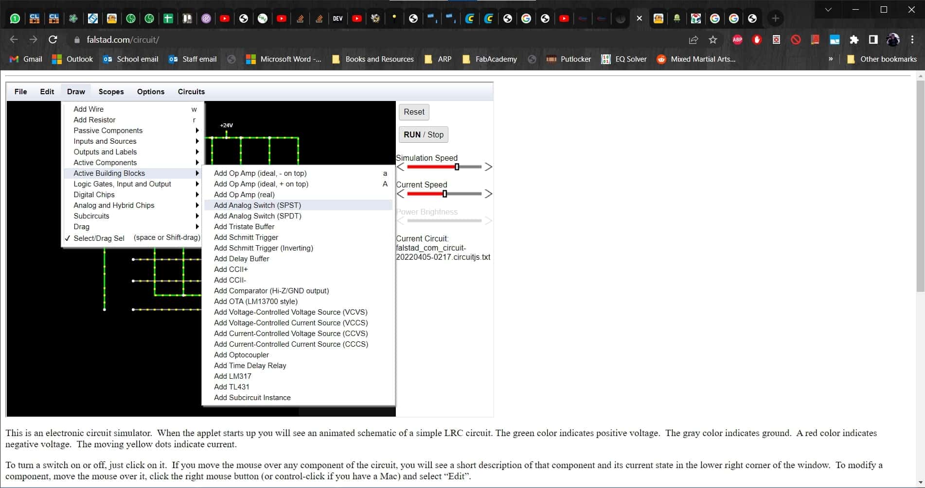
I spent an entire day on this problem and got nowhere. I was feeling very frustrated and defeated and I hadn't even built it in reality yet. Finally, Leen took a look at it for me and realized that I was using the wrong kind of switch. Not knowing any better, I had selected powered switches that provide current even when the switch is open, and I needed to select passive switches instead.
Passive Switches
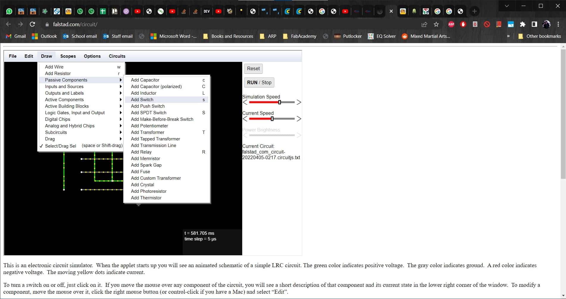
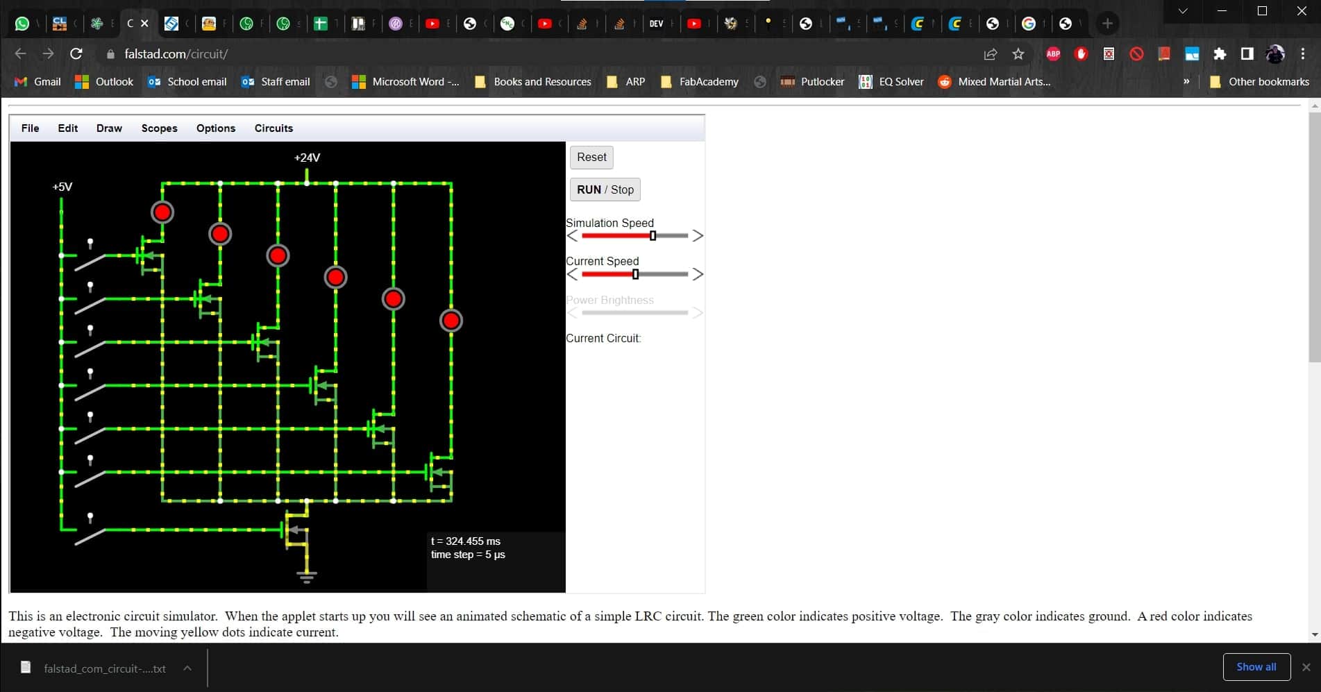
So I swapped out all of the switches in the circuit,
Successful Simulation
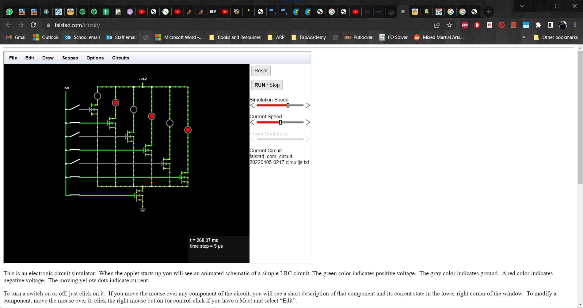
and finally, everything was working as I had expected from the very beginning.
Putting It All Together
Scrap Cable
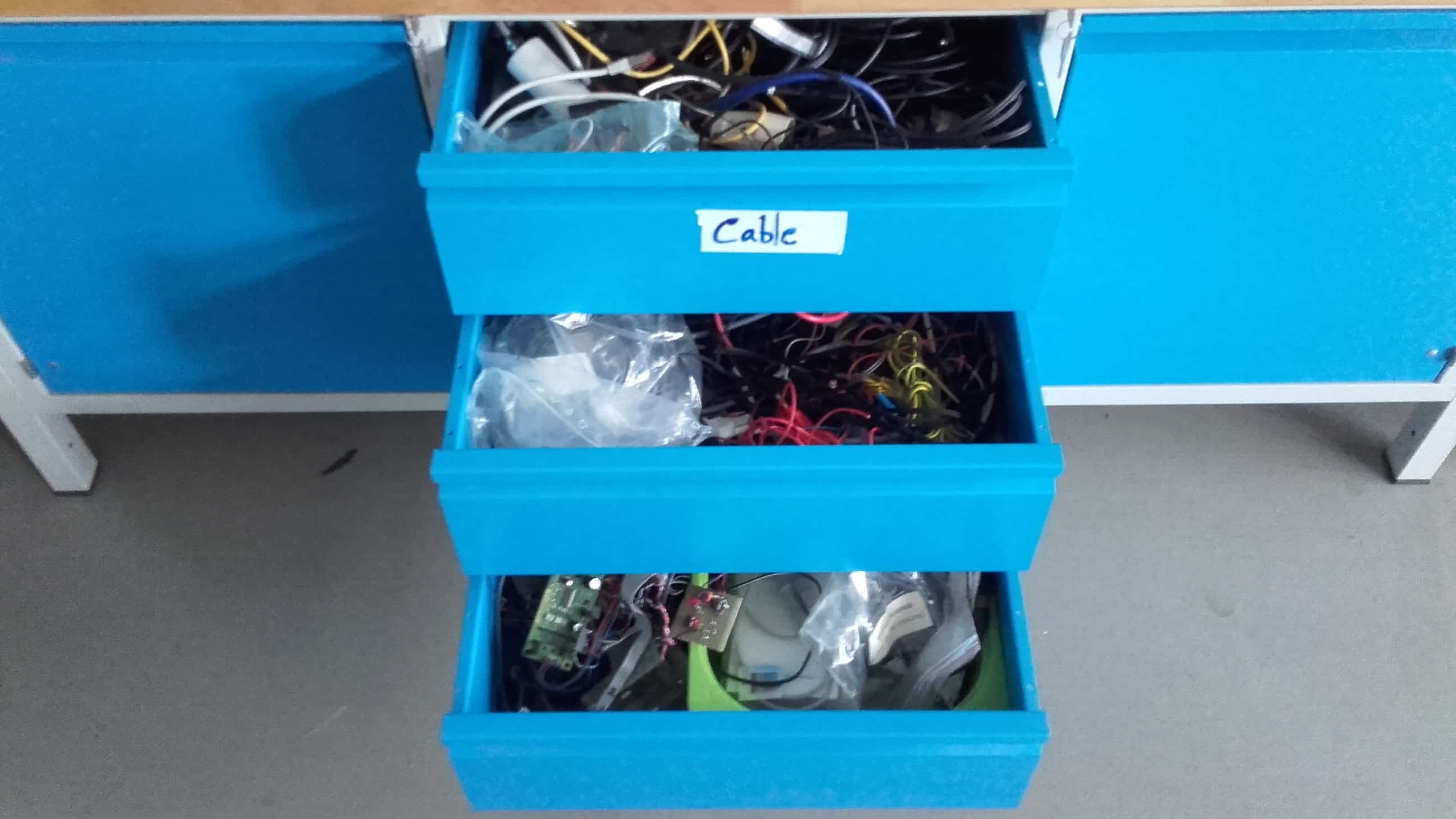
Once the simulation was finally working, I was ready to build it. We have a cabinet with a metric ton of scrap cables and parts so I got into it hoping to save myself some soldering time.
Excellent!
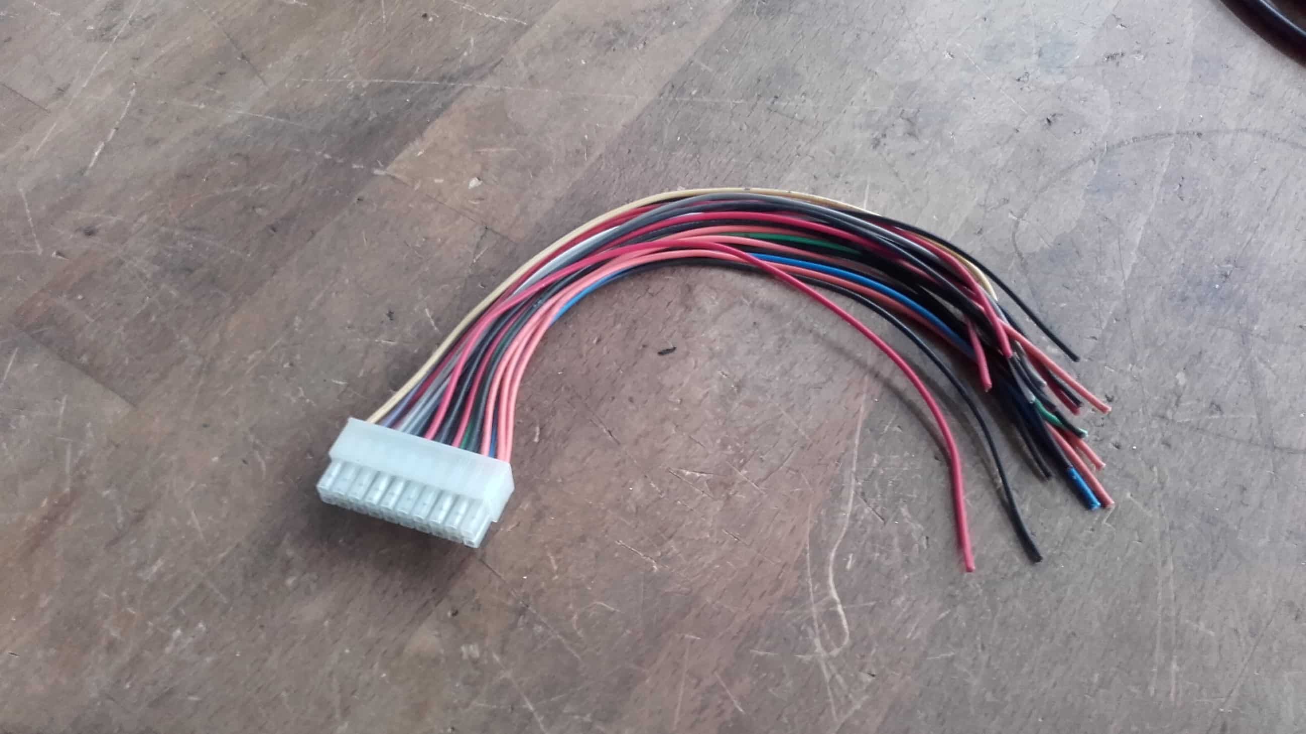
After a few minutes of searching, I found a piece of scrap that was almost perfect. It had ten pairs of wires connected in some kind of housing. The pairs of wires each plugged perfectly into my buttons; I just needed to separate them.
Preparing the Wires
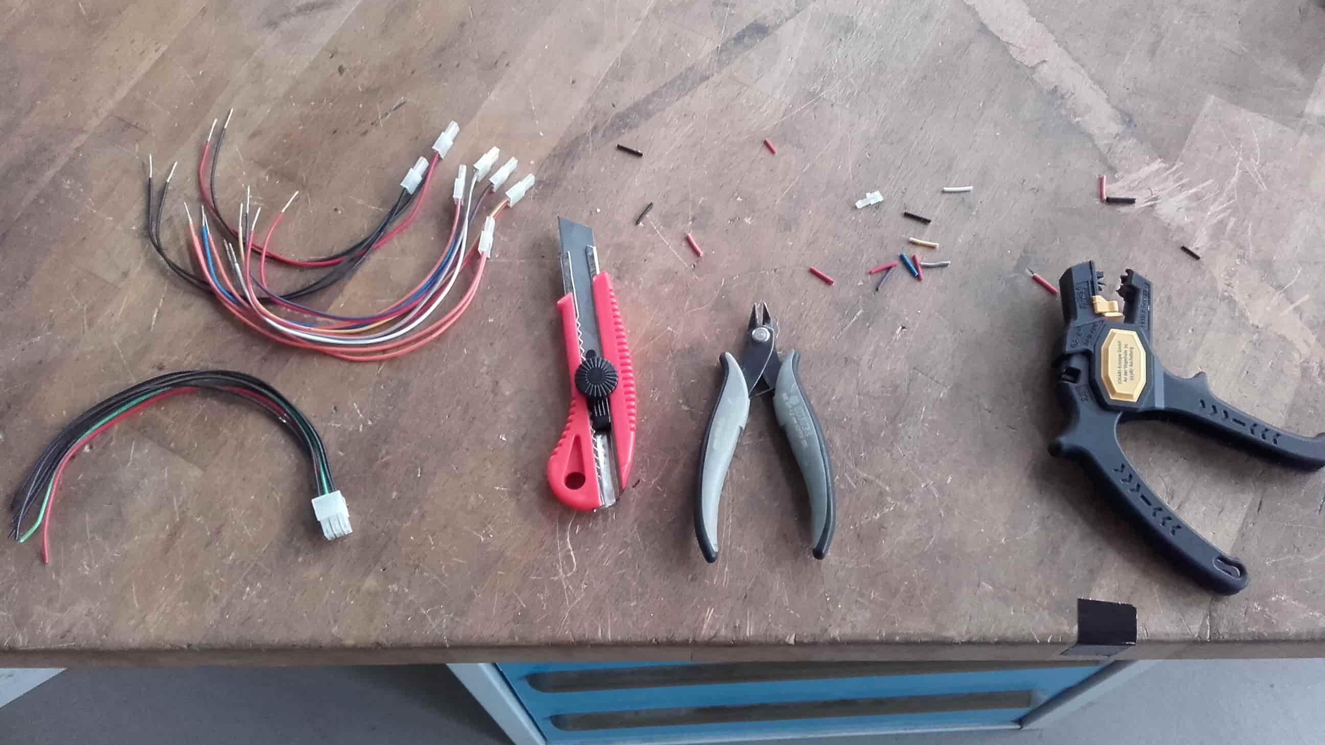
I cut off the seven pairs of wires I would need and stripped the ends.
Soldering
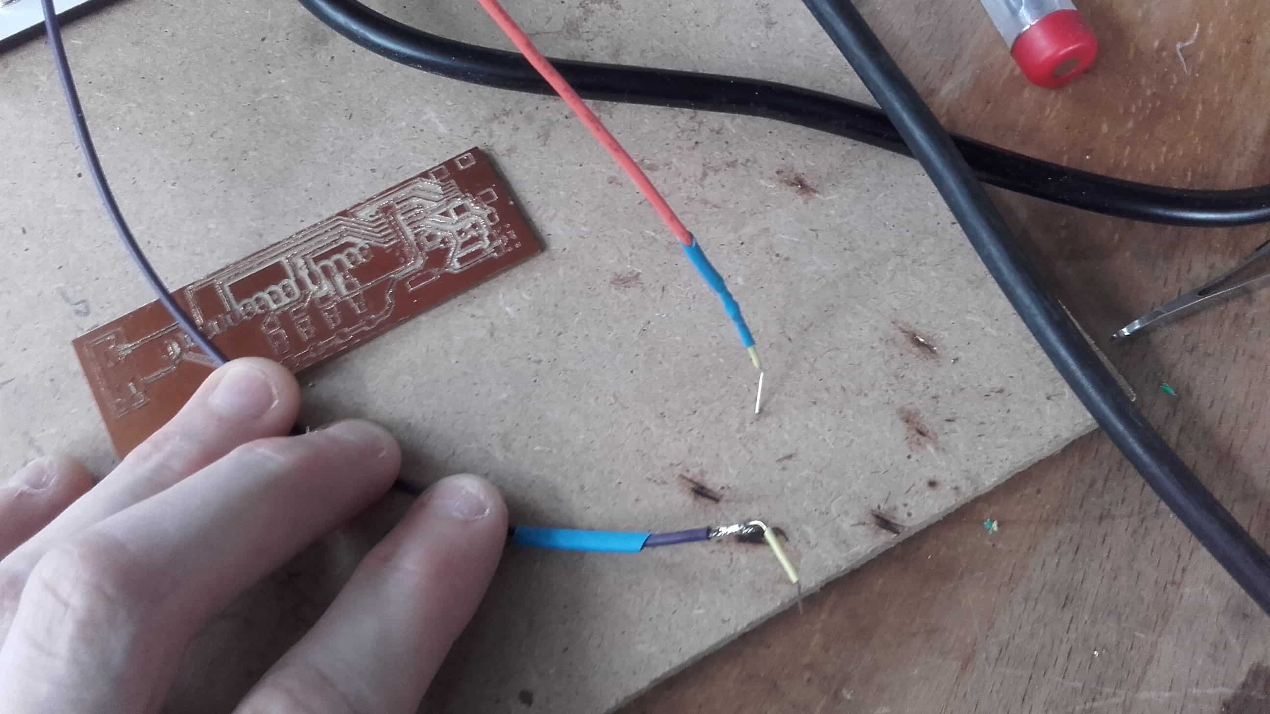
And then quickly soldered and shrink-wrapped some jumper wires to them so they could easily plug into a breadboard or pinheader.
Good Connection
They fit nicely into the back of the button panel. This will really help to keep everything organized and fairly structurally sound for a breadboard circuit. I got the circuit all put together, not forgetting to add resistors in series with each of my LEDs to prevent overloading them. This online calculator helped me determine their size.
Almost, but Still Weird
However, once again, things weren't quite working as expected. The LEDs were lighting up, so that was a good sign, but they were lit up even when the buttons weren't pushed; pushing the buttons just made them brighter, and then they stayed bright even after releasing the buttons. Weird.
Missing Resistors
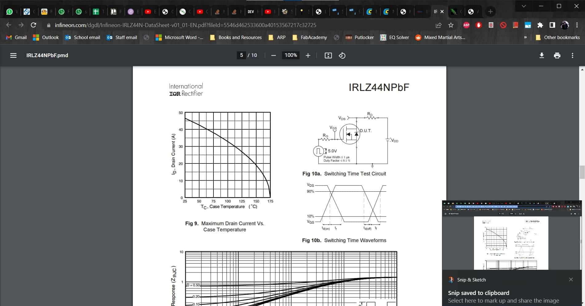 datasheet
So I spent some time with the datasheet for the MOSFETs I was using. Once again, this got me nowhere...but Leen (my hero this week 🤗) noticed that there needs to be a resistor between the gates of the MOSFETs and the ground.
Finally Working
So I added the missing resistors and everything was finally working as intended. Now I just need to figure out how to control this with my board.
Writing the Code
Change of Plans
These projects got away from me a bit and before I figured out how to get the buttons to work, I decided to change my inputs to ultrasonic sensors. During Input Devices Week, I played around with the sensors quite a bit, and we had a box of them left over from an old project in the lab, so I decided to change my idea for the final project. I am much happier with the sensors since they will not require actually touching the map to interact with it. This is especially nice for something that is designed to be hung on a wall. Also, I know they are not ideal for ranging; if I needed the ranging functionality, then I would have gone with another technology, but I only want them to act like a switch, so they are perfect for this application.
I did all of the coding for this project in the Arduino IDE. I think I am getting the hang of using the examples in combination with the Arduino Reference page. Don't tell anybody, but I might actually be starting to have a little fun with this stuff.
Declaring Variables
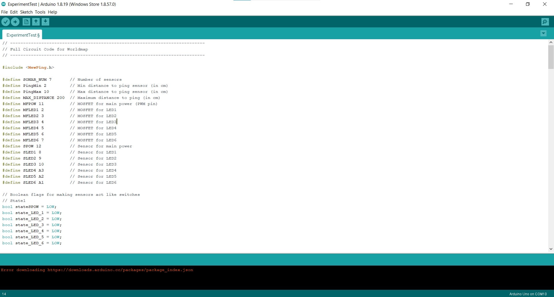
I started by defining a few variables for the sensor parameters and then gave each of my components names and set them equal to their Arduino pin numbers.
Boolean Flags
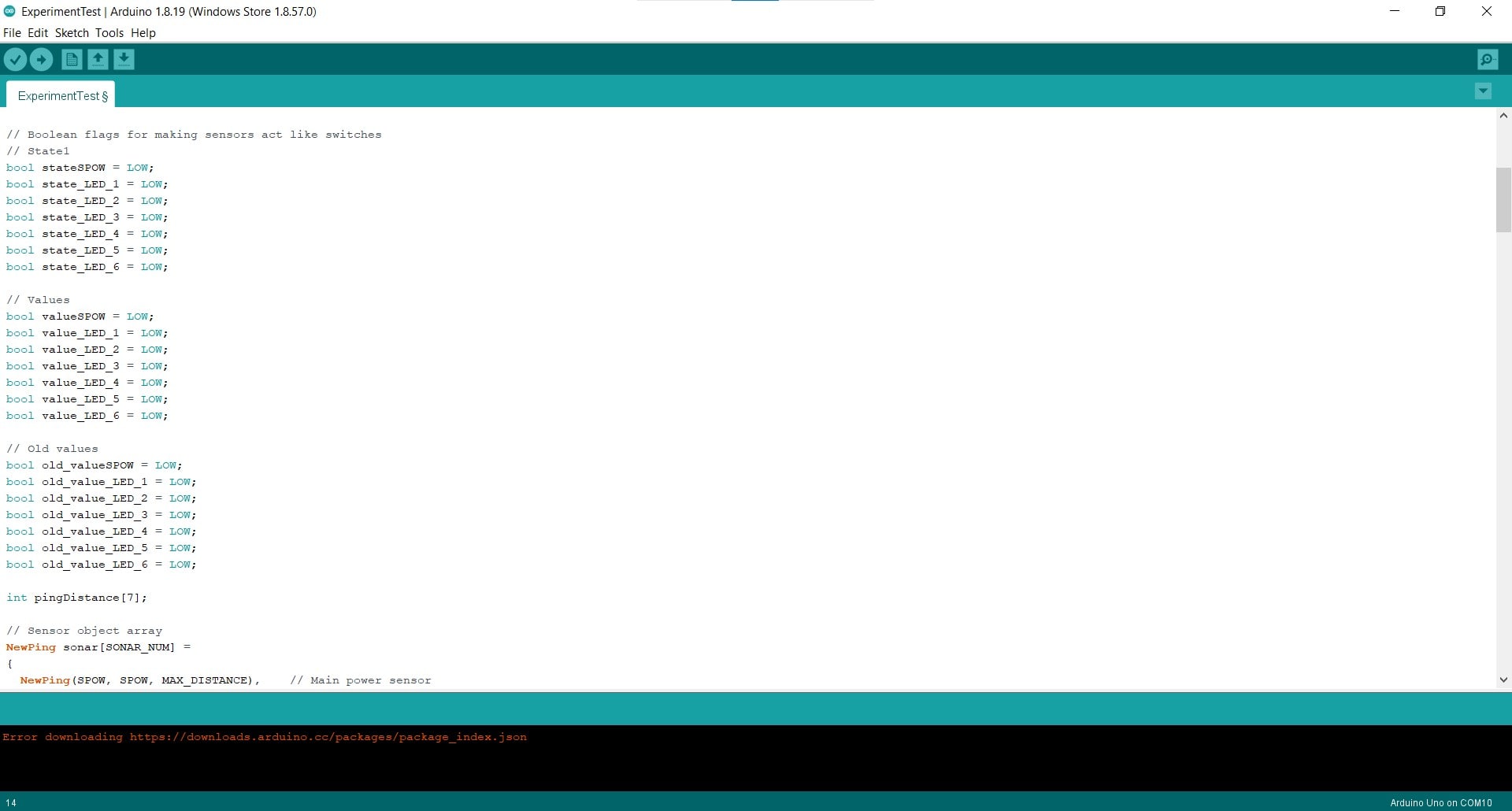
I also created boolean flag variables for each of my branches. These would help me make my sensors act like flip switches and I will explain how they work when I get down to the main loop.
Sensor Object Array
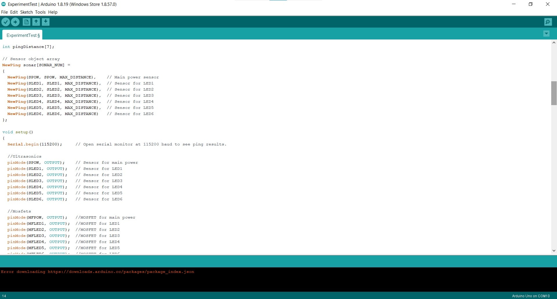
Next I created an array for the sensors. The functionality and syntax are from the example code; I just changed the names and added more sensors since I have seven in my project.
Pin Declarations
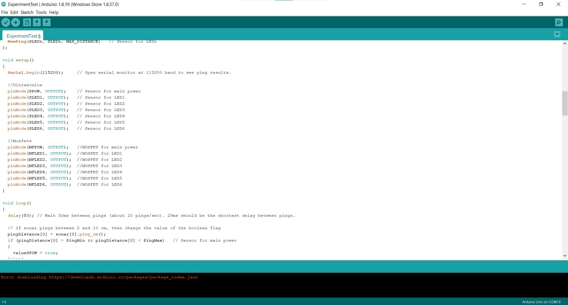
Then I assigned all of my pin connections. Since I am hacking the sensors with the NewPing library, both the trigger and echo pins for each sensor are connected to the same pins on the microcontroller. Therefore, they are acting as both INPUTS and OUTPUTS. The syntax in this situation, is to assign them all as OUTPUTS.
From Ranging to Switching
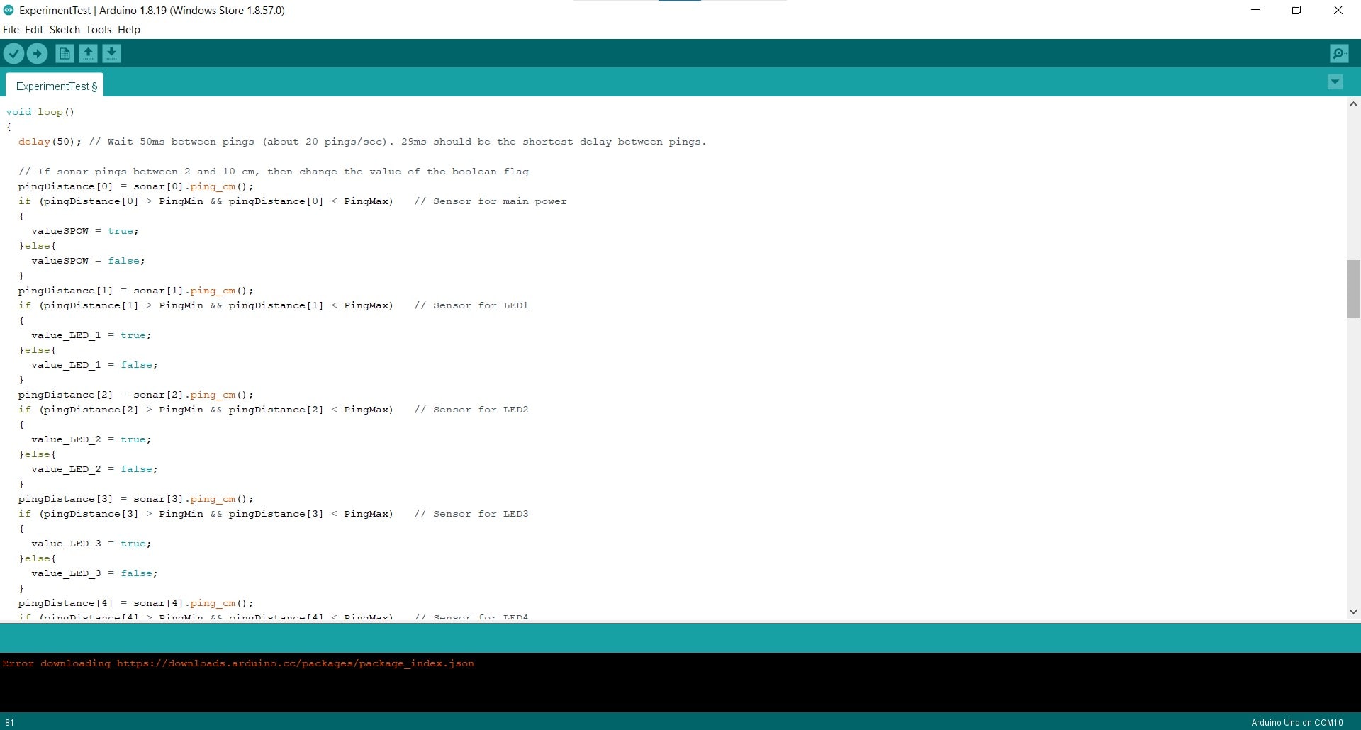
The first part of the loop, and indeed most of the code, is focused on getting the ranging sensors to act like switches instead. The sensors ping every 50 ms and the value of the most current ping is stored in the pingDistance array and compared to the PingMin and PingMax variables. If the ping is between 2 and 10 cm from the sensor, then the value of the the flag changes.
If-Statement for Main Power
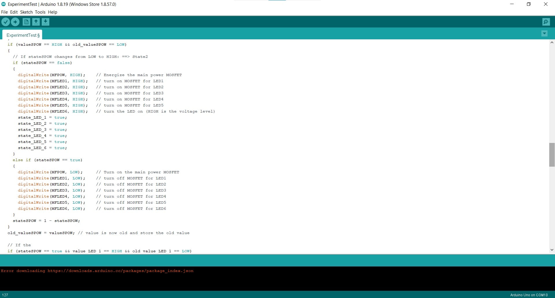
If the value for the main sensor changes from LOW to HIGH, and the state of the sensor is LOW (i.e. if the sensor is triggered by a ping within the defined parameters), then turn on the MOSFETs for all of the LED panels and change the states to HIGH. Otherwise, keep everything off.
If-Statements for Panels
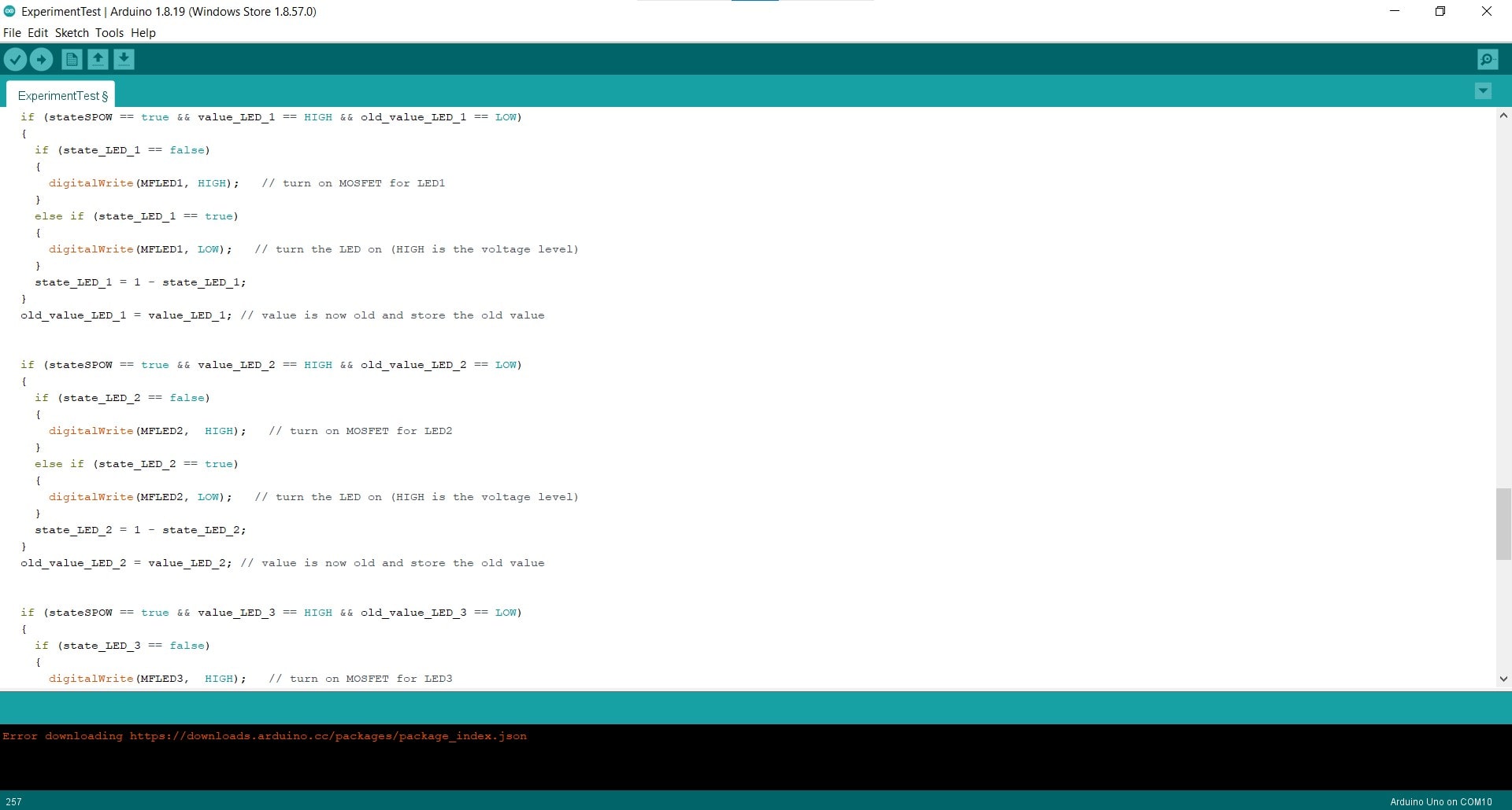
Then there are the if-statements for the sensors on the individual panels. These work the same as the main power sensor, but they only work if the main sensor is currently HIGH (i.e. if the map is on).
How the Code Works
All of the variables and flags begin as LOW. When the sensors ping inside the given threshold, the value associated with that sensor changes to HIGH. When this happens for the main sensor, if the old_value and state are both LOW (which they are at this point), then the controller writes all of the MOSFETs to HIGH and the states of the LEDs are changed to HIGH. Still inside this loop, the state of the main sensor (now 0) becomes equal to 1 - itself (so 1-0=1 now). Then the old_value changes to the current value. So now, the map is on, the old value is HIGH and the state is also HIGH.
The next time the code iterates, it will not enter the if-statement (since value is LOW without a ping and the old_value is still HIGH), it will simply go to the next line which makes the old_value equal to the value, so it becomes LOW once more - basically reset for the next ping. The next time the main power sensor pings, we enter the inner if-statement once again, but this time the state is LOW so all the LEDs are turned off. The if-statements for the panels work the same way, but they can only be activated if the map is on.
Hero Video
I know the code could be cleaned up a lot if I understood arrays better. I am aware that writing essentially the same code seven times is silly and inefficient; I am just already at the limit of my skills and I was very very happy that it turned on and functioned at all.