Computer-Controlled Cutting
Hero Shots
Click Here for Our Group Assignment
Laser Cutter
File Downloads From This Week
- Clearance Comb SLDPRT
- Clearance Comb DXF
- Clearance Comb svg
- Clearance Comb gcode
- Engraving Test svg
- Clock Face SLDPRT
- Clock Face DXF
- Clock Face svg
- Clock Face gcode
- Clock Back Plate SLDPRT
- Clock Back Plate DXF
- Clock Back Plate svg
- Clock Back Plate gcode
- Clock Sides SLDPRT
- Clock Sides DXF
- Clock Sides svg
- Clock Sides gcode
- Construx Part DXF
- Construx Part svg
- Construx Part gcode
Vinyl Cutter
Initial Reaction
I am feeling pretty good going into this week. I have never used a laser cutter or vinyl cutter before, but they are hugely applicable for modern manufacturing so I am really looking forward to getting some experience with them. This week, there are two individual assignments and a group assignment. As a group, we need to characterize the laser cutter's focus, power, speed, rate, kerf, joint clearance and types. The individual assignments are to cut something on the vinyl cutter, and to design, lasercut, and document a parametric construction kit that accounts for the kerf and can be assembled in multiple ways. I am hoping that the design work I did last week will set me up well to be able to just focus on the cutting itself.
After Local Workshop
The local workshop was short and sweet this week. Since we spent so much time on the laser cutter last week, we just had a presentation about how the vinyl cutter works and how to use it to make stickers and appliqués for thermally transfering designs to fabrics. The machine looks easy to use and fun! I am excited to get to the lab and try it out.
The Vinyl Cutter
Disclaimer
Unfortunately, I must begin this section by reporting on a failure. While searching for screen-capturing software, I was delighted to learn of the Xbox Game Bar and that it is already built-in to my laptop with a screen capturing tool. At the beginning of the group session with my group-mates, Leen and Roland, I started the screen capture. I was intending to use it along with the camera on my phone to take the images and screenshots that would be needed to document the day's events. Unfortunately, I screwed it up somehow. I must have gotten some setting incorrect and, unknown to me, it stopped recording after only one minute and eight seconds. So, I had to recreate the session purely for the purpose of the forthcoming screenshots. This is why the more observant among you may notice that the screenshots do not perfectly match the images from my phone camera. My bad. 😬
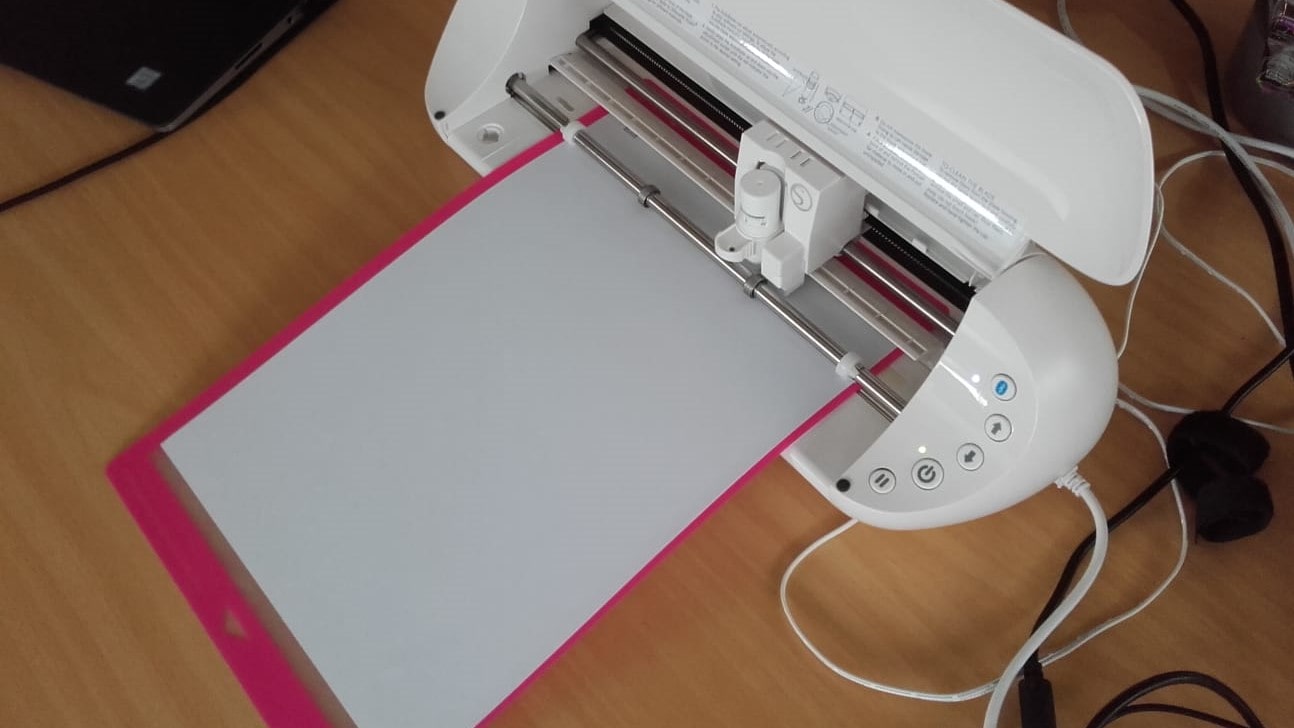
Portrait 2 from Silhouette Studio
In our lab, we use the Portrait 2 vinyl cutter from Silhouette Studio. It is very cute and seems nicely made. It was also easy to connect via Bluetooth.
Machine and Mat
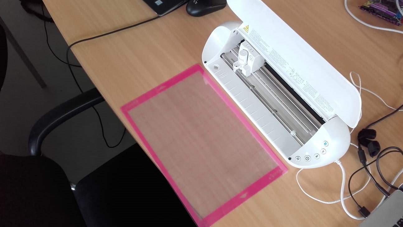
First, we set up the machine and cutting mat. Our instructor had not yet arrived with any vinyl, so we decided to test it out using paper.
Mounting the Copy Paper
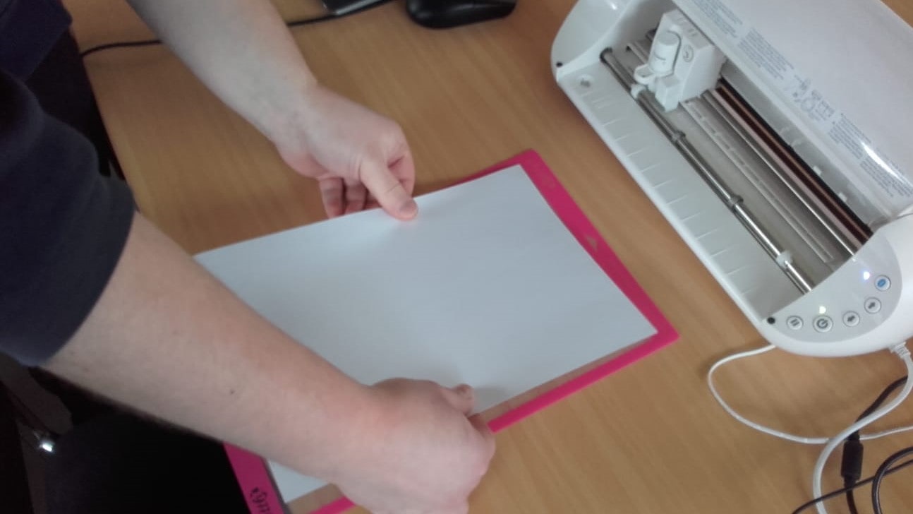
Mounting the copy paper onto the sticky side of the cutting mat was very easy.
Mounting the Cutting Mat
So was inserting the prepared cutting mat into the machine.
The Blade
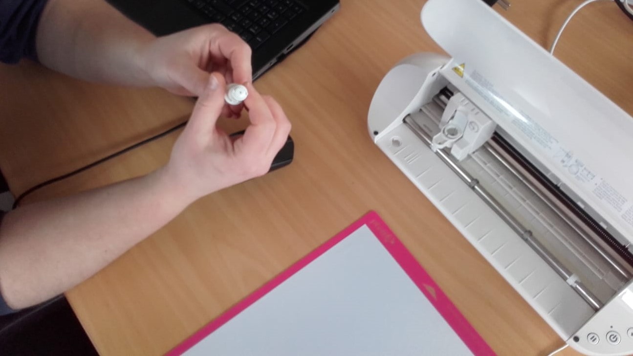
Roland showed us how to change the blade.
AutoBlade
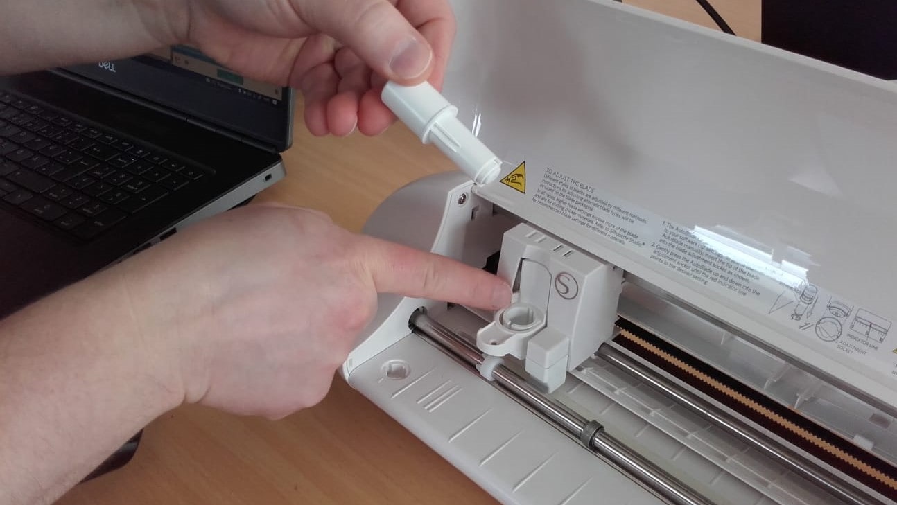
And how the AutoBlade feature works to automatically set the cutting depth.
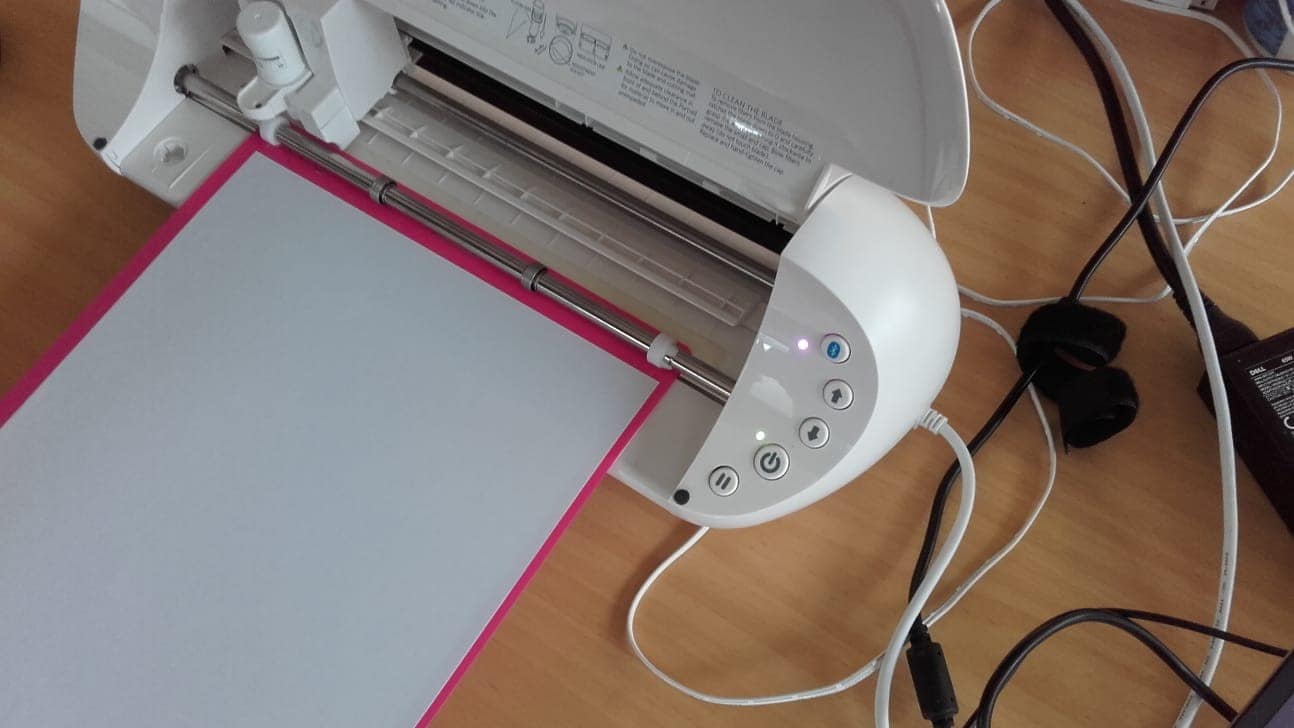
Ready, Set, Go!
All set up and ready for some input.
Silhouette Studio
All that was left was to download the GUI software for controlling the cutter from Silhouette Studio.
Opening the Image
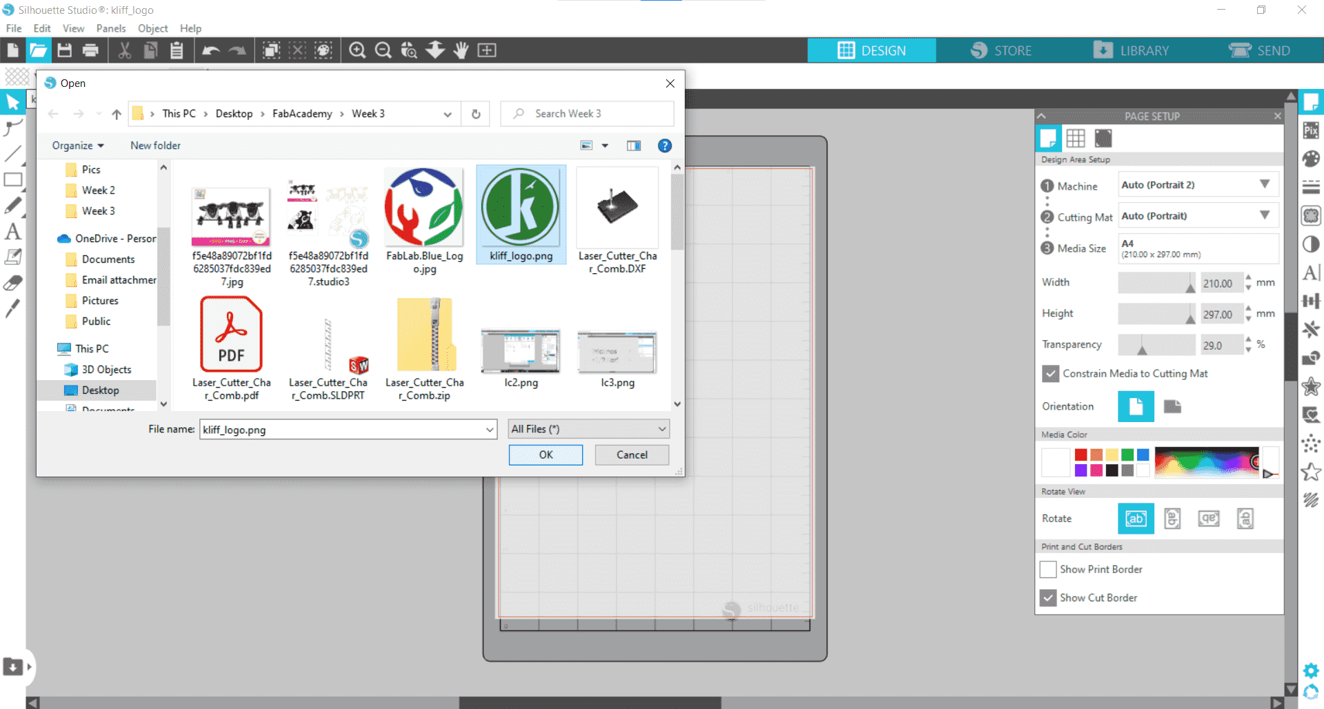
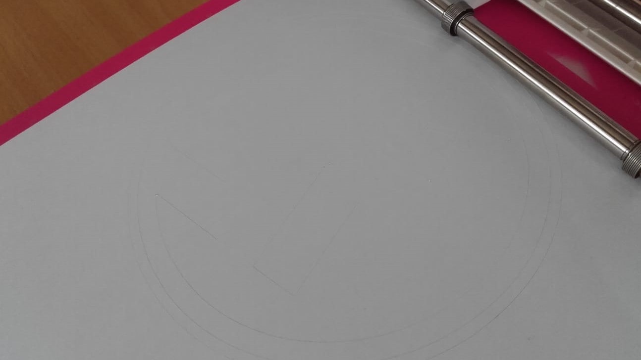
I began the testing by going to File/Open and choosing the image I wanted to cut.
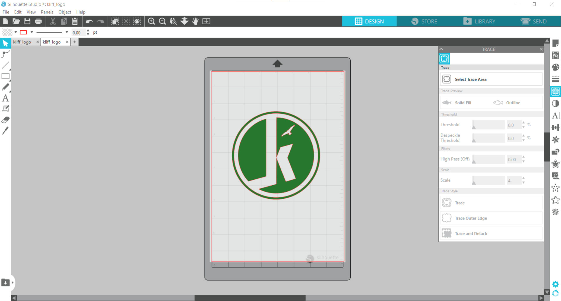
The Trace Tool
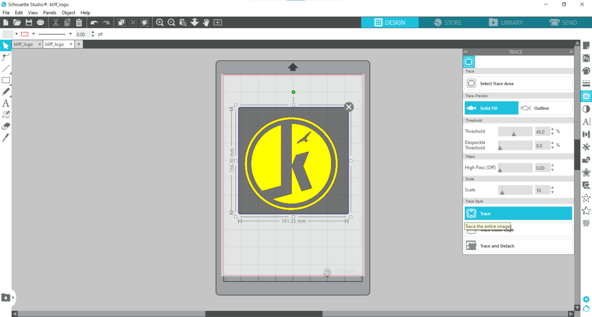
I created the path to cut by selecting the area using the Trace tool.
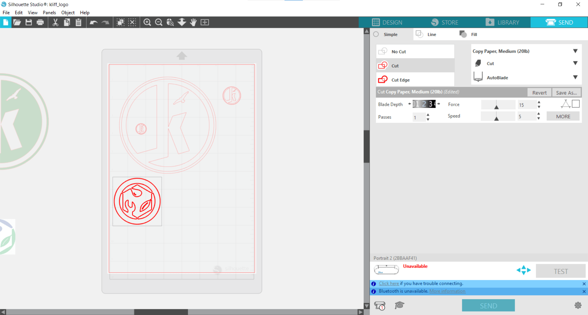
Setting the Material
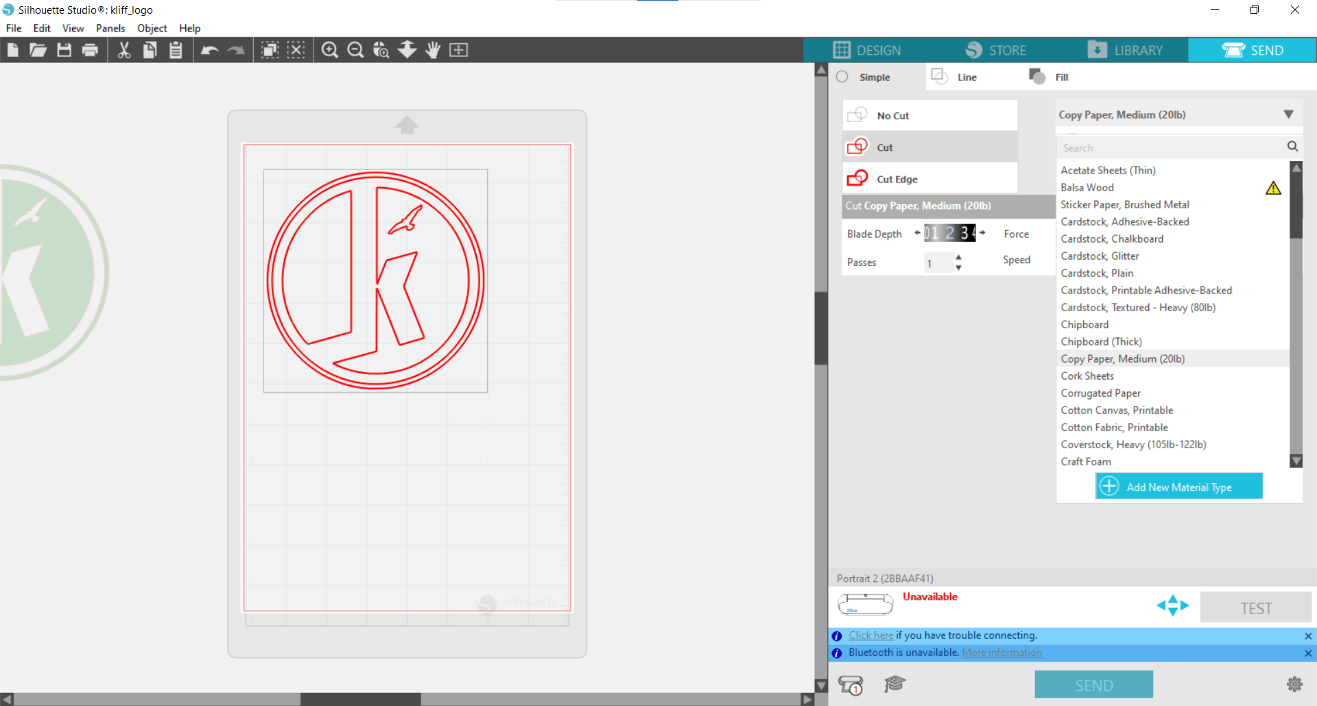
Moving the original off the workspace left me with the desired path for the cutter. Then in the Send tab, I changed the material to 20 lb copy paper.
Setting the Tool
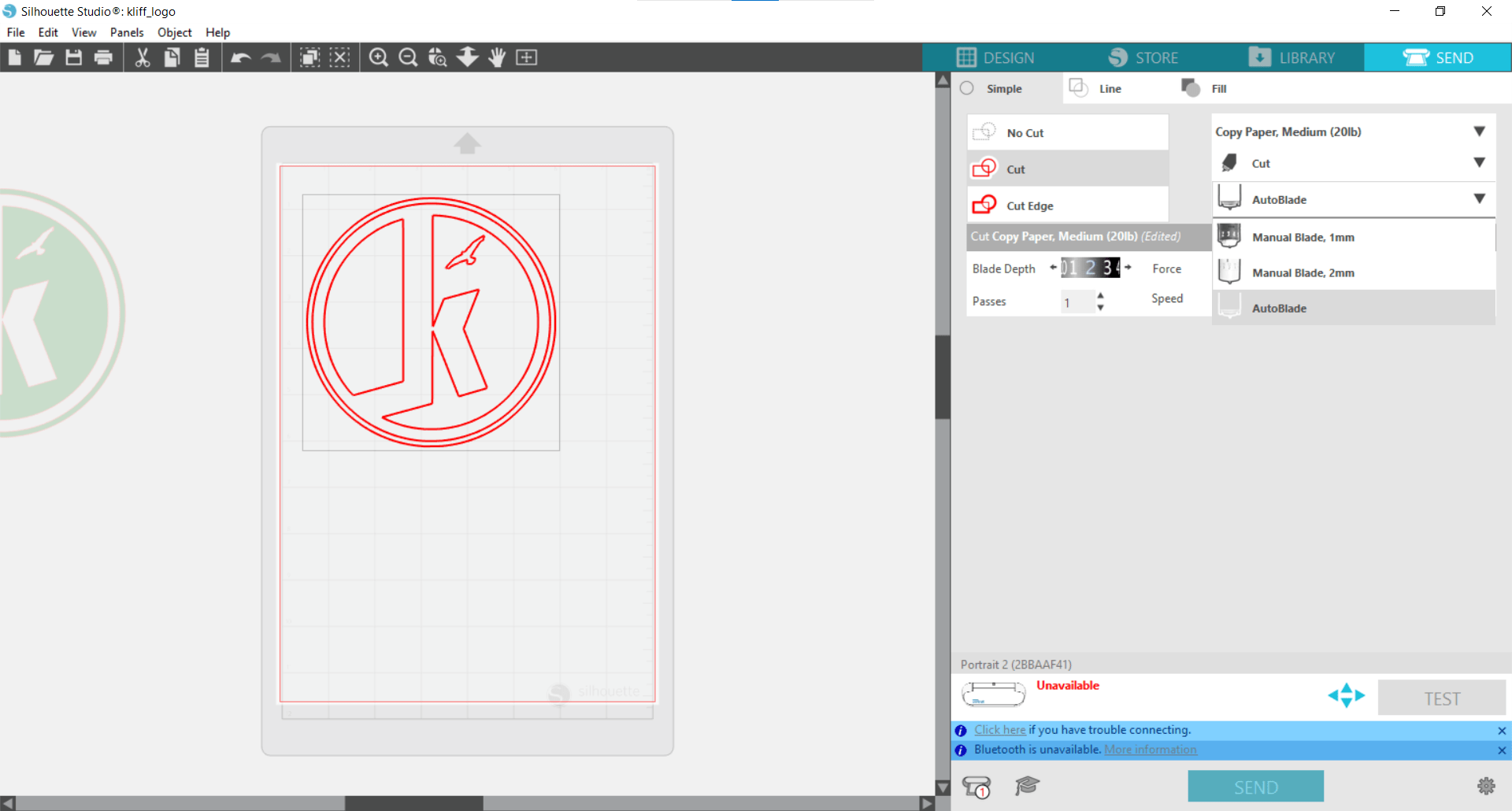
Next, I chose the tool. In this case, I went with the AutoBlade setting so the machine would set the blade depth and cutting force automatically.
Setting the Speed
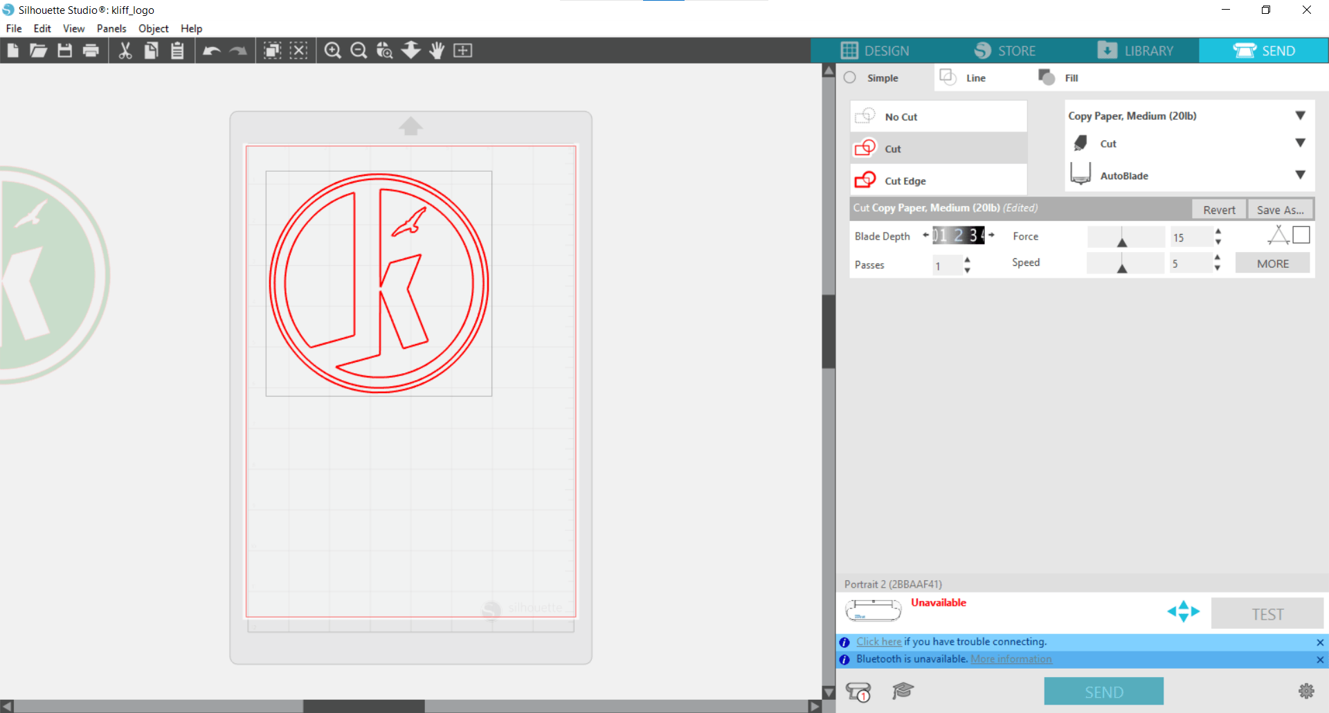
Finally I adjusted the cutting speed down to 5 and sent the job to the cutter.
The Cut
The cut went smoothly (even though the machine sounds terrible while cutting). There were no visible tears or damage so I was already starting to feel happy.
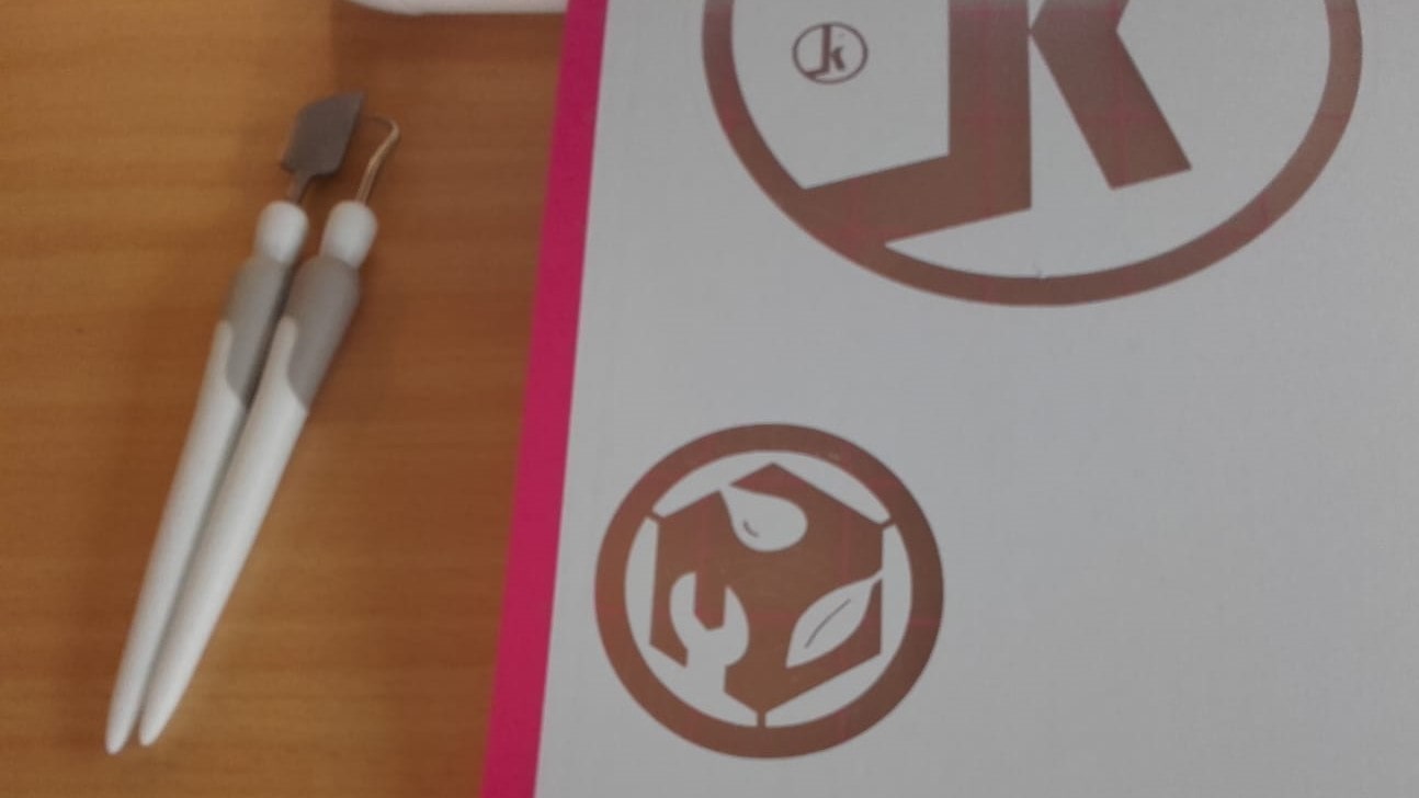
Weeding
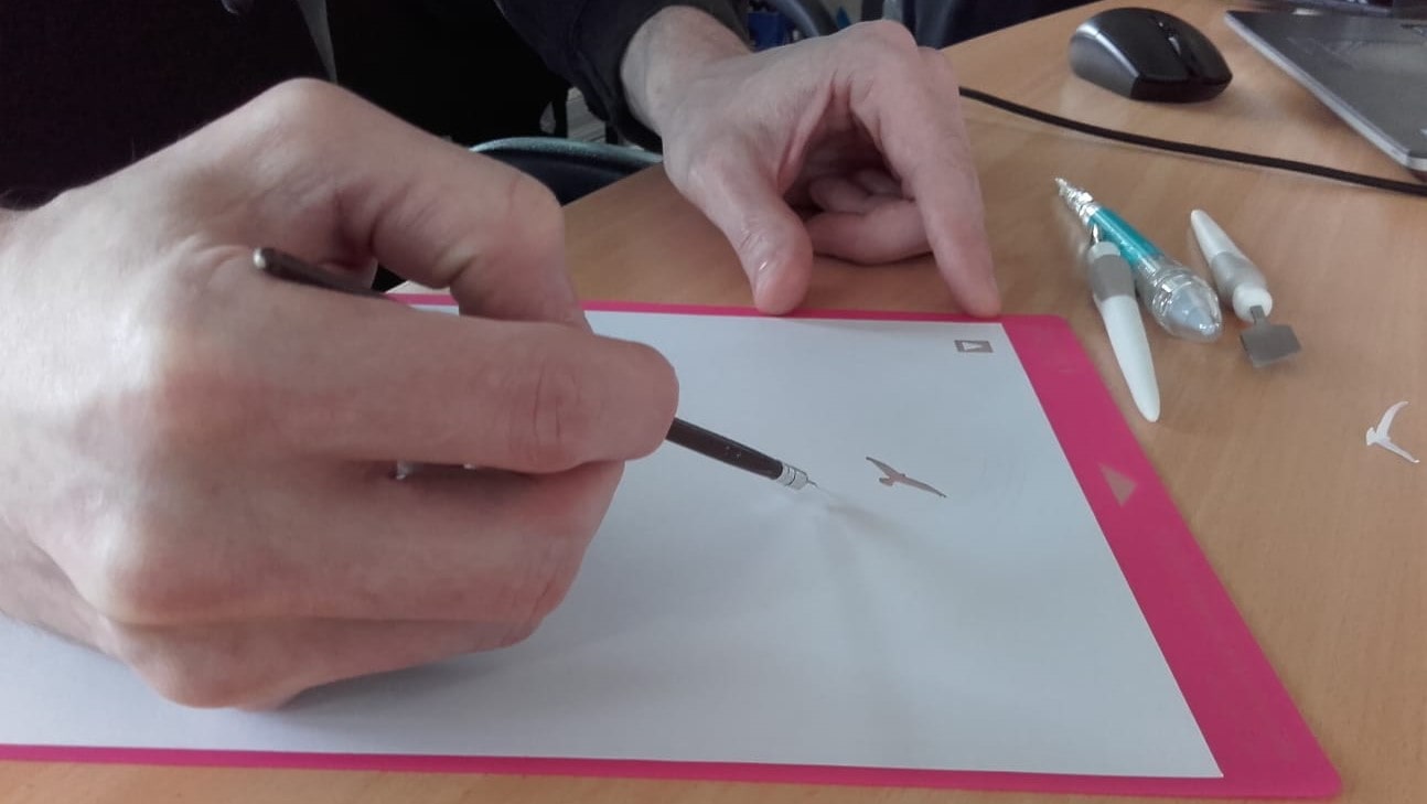
The final step was to weed the cut using a homemade weeding tool (bent sewing needle stuck into a pencil eraser) that worked much better than the retail design.
Result
The cut turned out great! Here you can see it with the settings I used.
Smaller Tests
Since the large test went so well, I repeated the process with two more smaller cuts using the same logo: one with a 25mm diameter, and the other with a 15mm diamter.
Smaller Results
These turned out great too! I am really impressed with the tiny details of which these machines are capable.
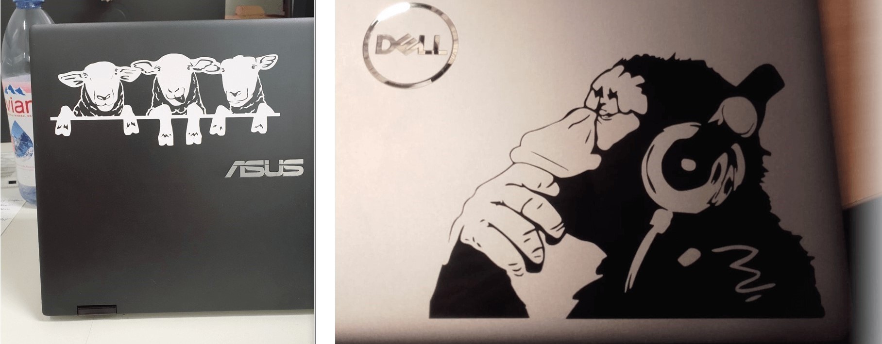
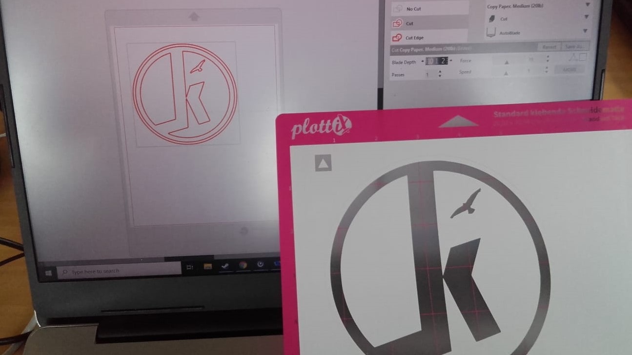
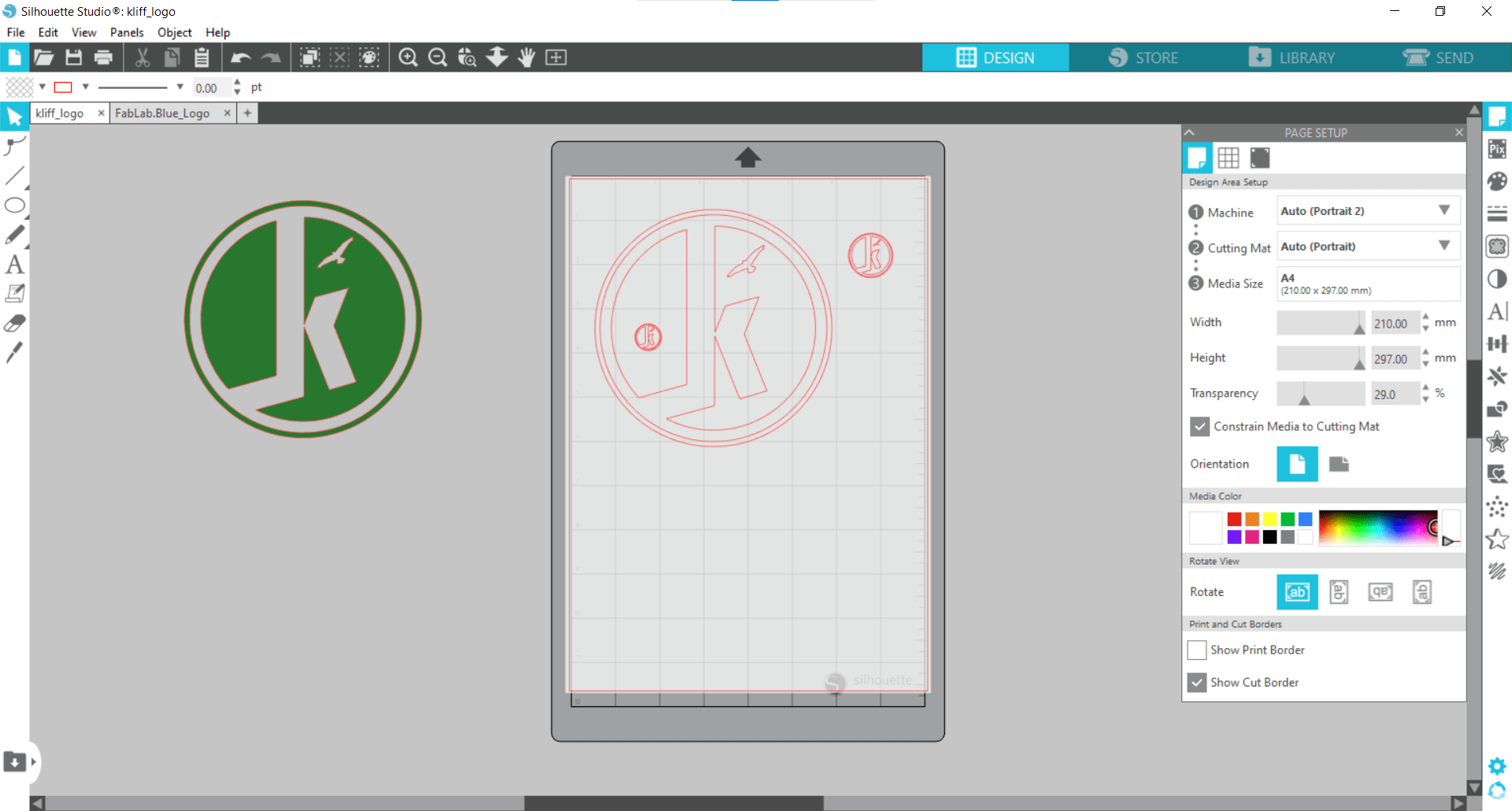
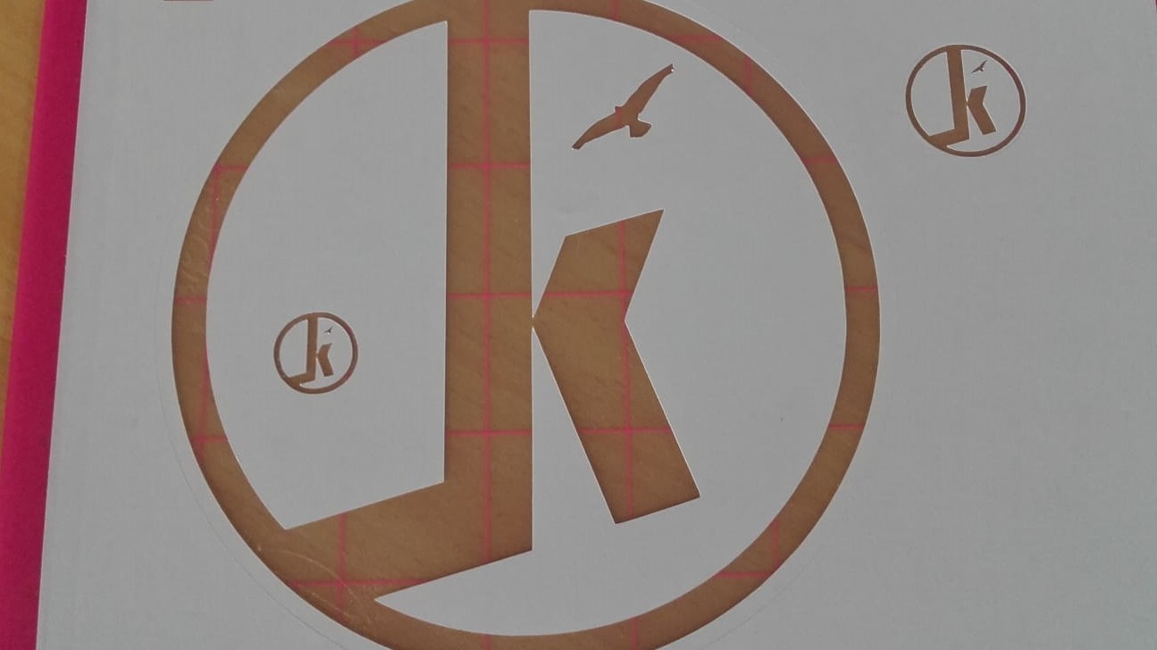
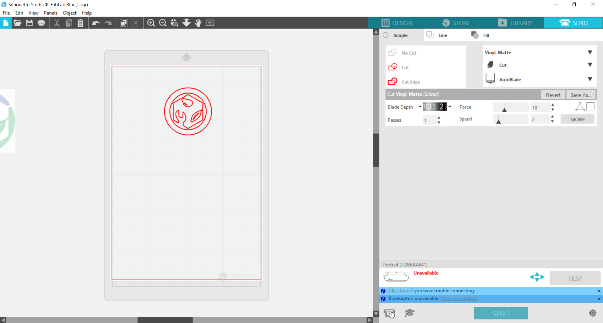
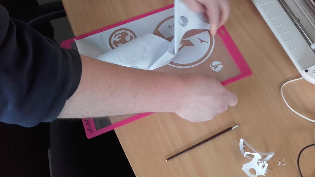
FabLab.Blue Logo
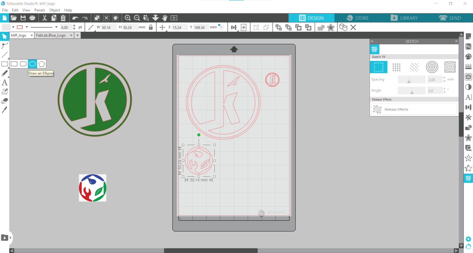
Next it was time to get more serious with the logo from our Lab. I imported it and traced it the same as before, but this time,
Adding Another Circle
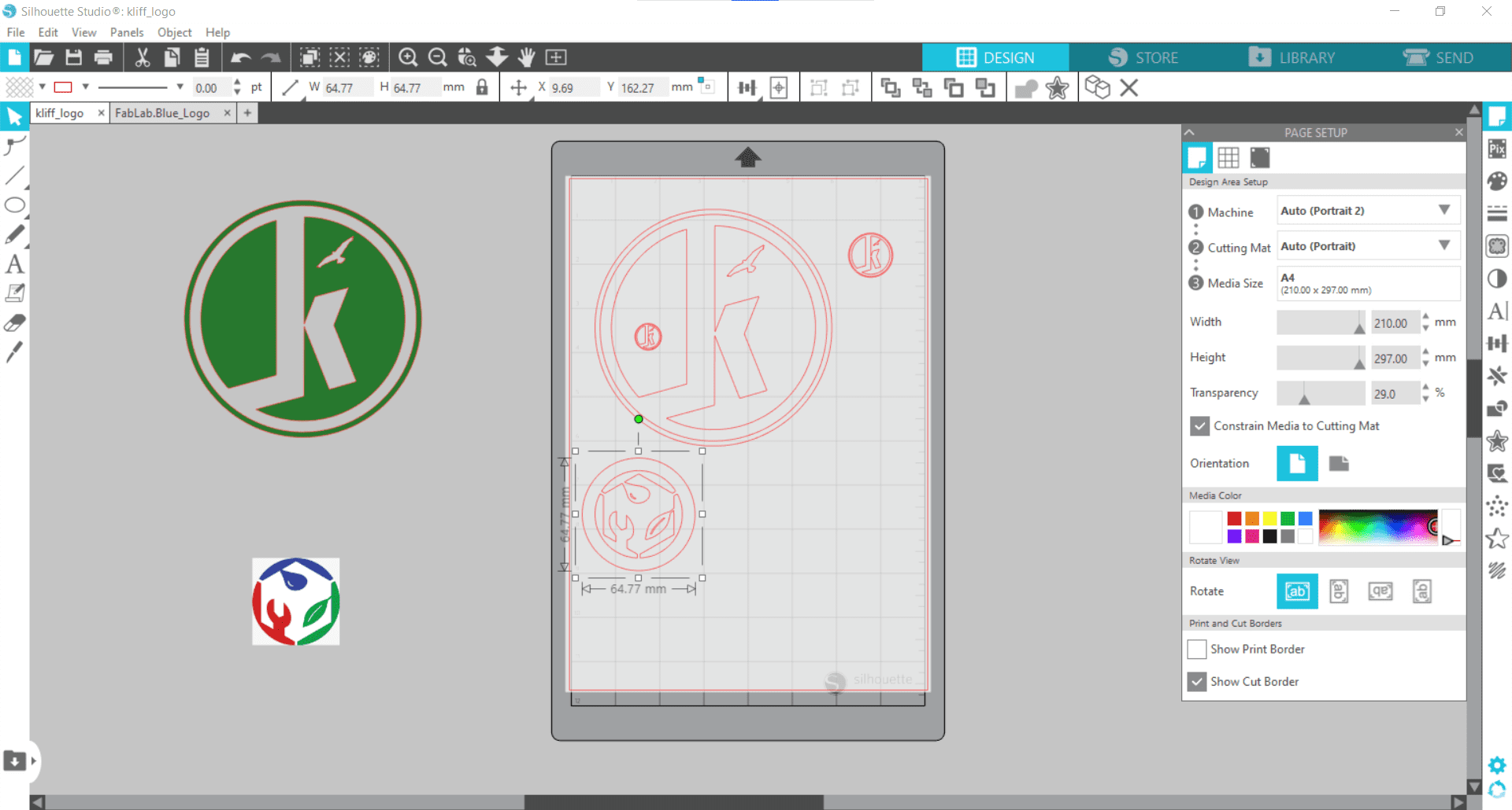
I needed another circle around it so the sticker would work properly. I added the shape using the Elipse tool and alligned it to the center of the logo.
Group Selected Shapes
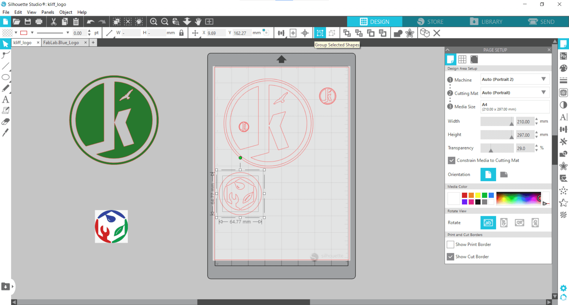
Then I used the Group Selected Shapes tool to group the two objects into a single cutting path.
Sent
And then sent it to the cutter again.
Not Perfect
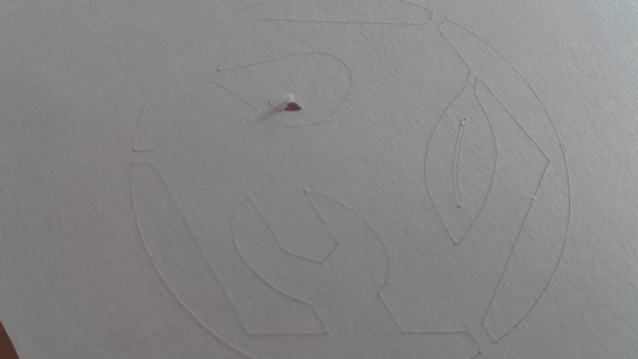
This time there was a small tear on the detail of the water droplet.
Result
But overall, the result still looked great after weeding.
Time to Cut Vinyl
That was enough testing on paper. It was time to try this out on a piece of scrap vinyl.
Preparing the Cutting Pad
The extra paper also needed to be removed form the cutting mat to make room for the vinyl.
Calibrating Cutting Area
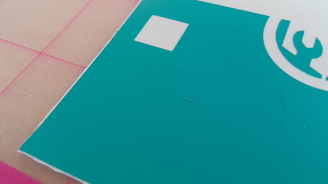
It took a couple tries to get the cutter to find the small part of the cutting mat where we had mounted the scrap vinyl.
Weeding
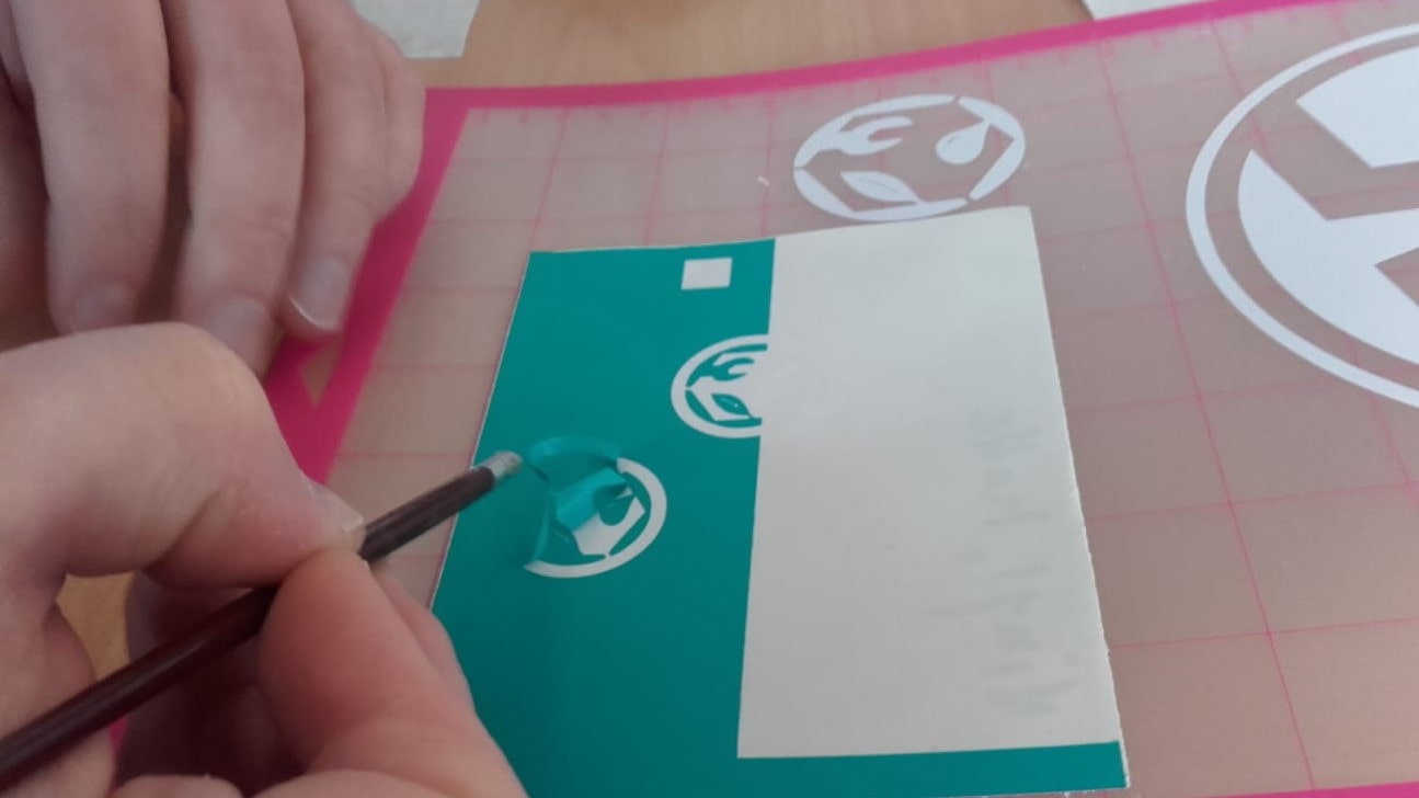
Once we found the vinyl, the cut went perfectly, and it was carefully weeded.
Transfer Tape
Next, we applied transfer tape to separate the newly cut sticker from its sticky backing.
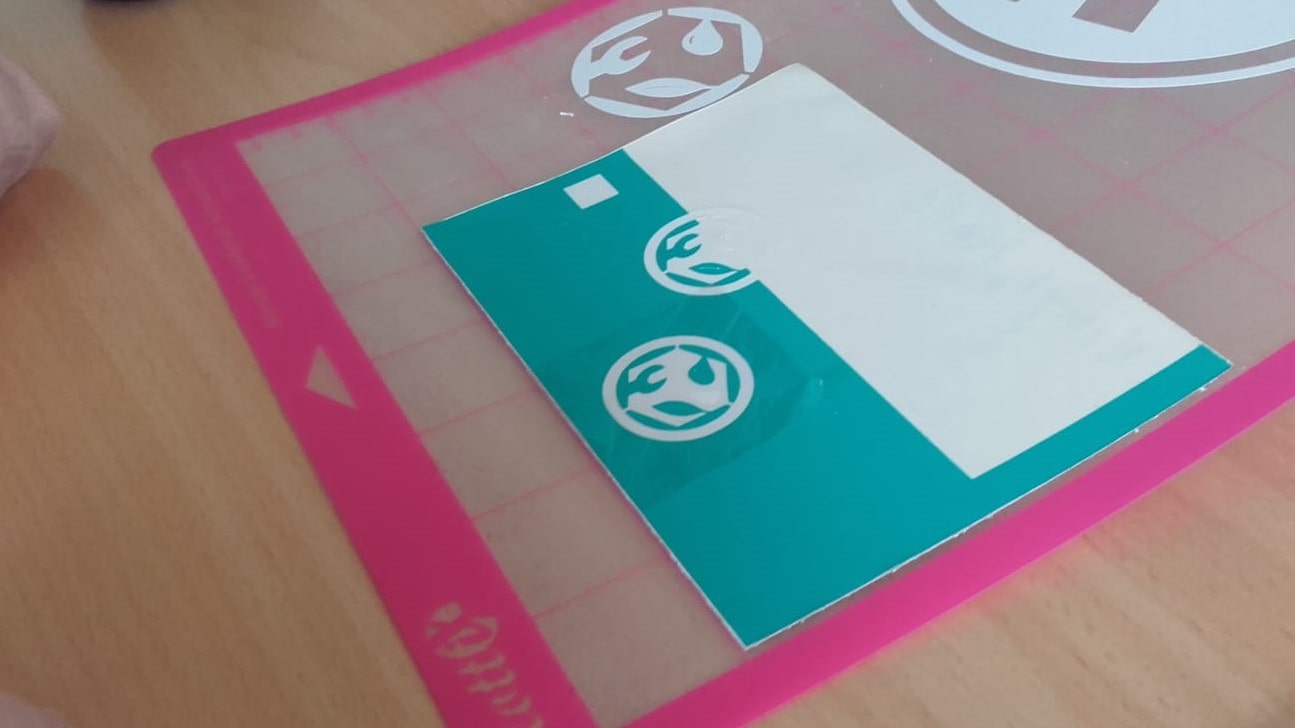
Removing the Sticker
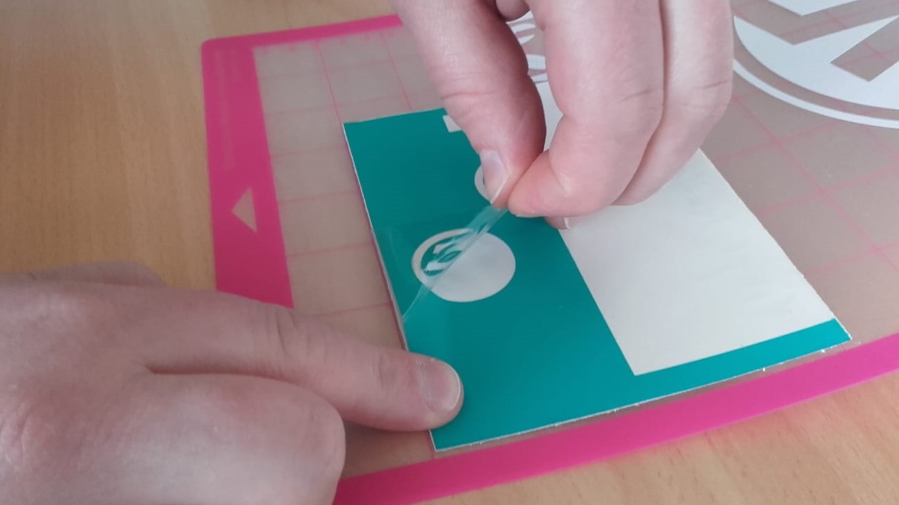
And then carefully removed the sticker, ensuring that all the pieces came up together and in their proper placement.
Result
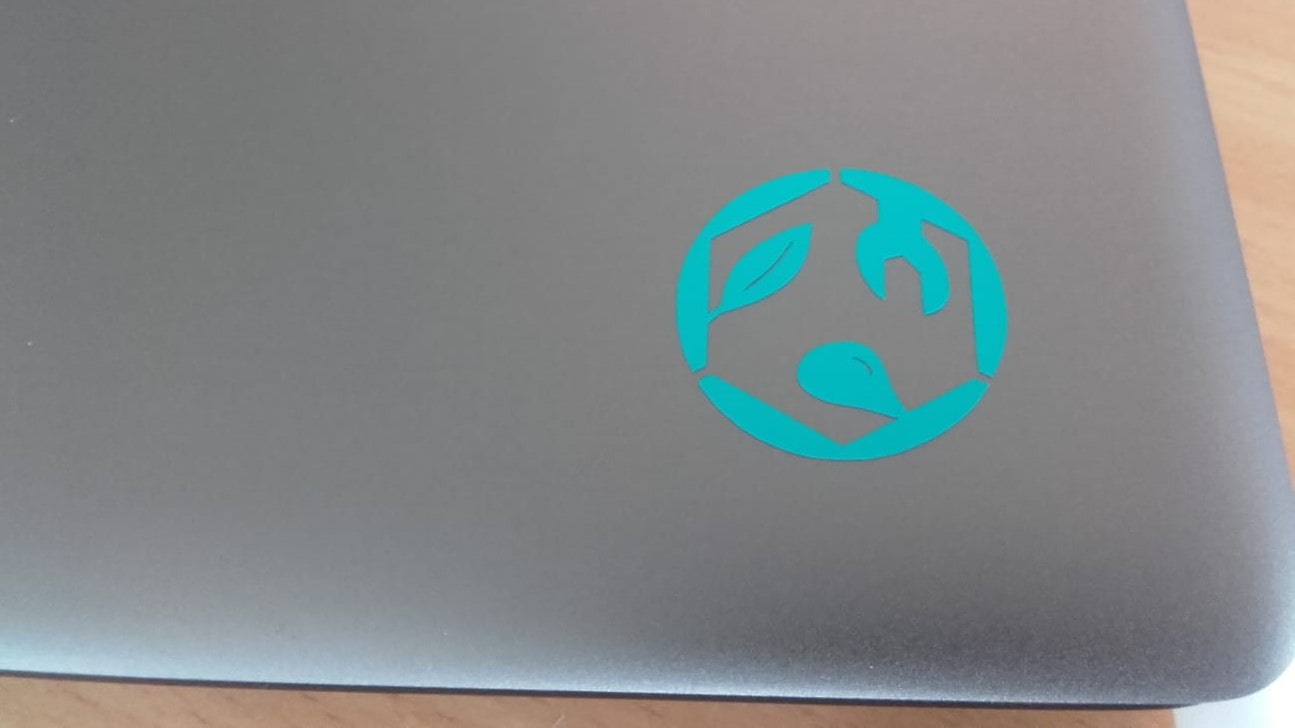
The result looked awesome on Roland's laptop.
Negative
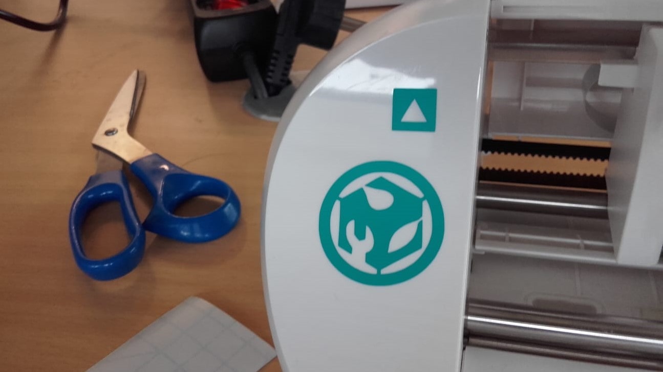
Even the negative looked great so we used it to add a bit of decoration to the vinyl cutter.
Just for Fun
I decided to cut a few more stickers just for fun.
Results
They also turned out fabulously! I am excited about this new toy!
The Laser Cutter
Group Assignment
My Contribution
For our group assignment, we would need to create a few CAD parts to be cut on the laser cutter in order to characterize it. Roland and Leen were intending to design some parts that could be used to measure the kerf and the parameters that are ideal for our specific laser cutter, the Fabulaser-Mini. With their measurements, we were able to determine the kerf of our machine to be 0.21 mm and the ideal focus distance is 5.14 mm (for a plywood material with 5.72 mm thickness). We also learned that the power settings and cutting speeds are functions of each other. For power 100, we used speed 1.5 for cutting and speed 20 for marking.
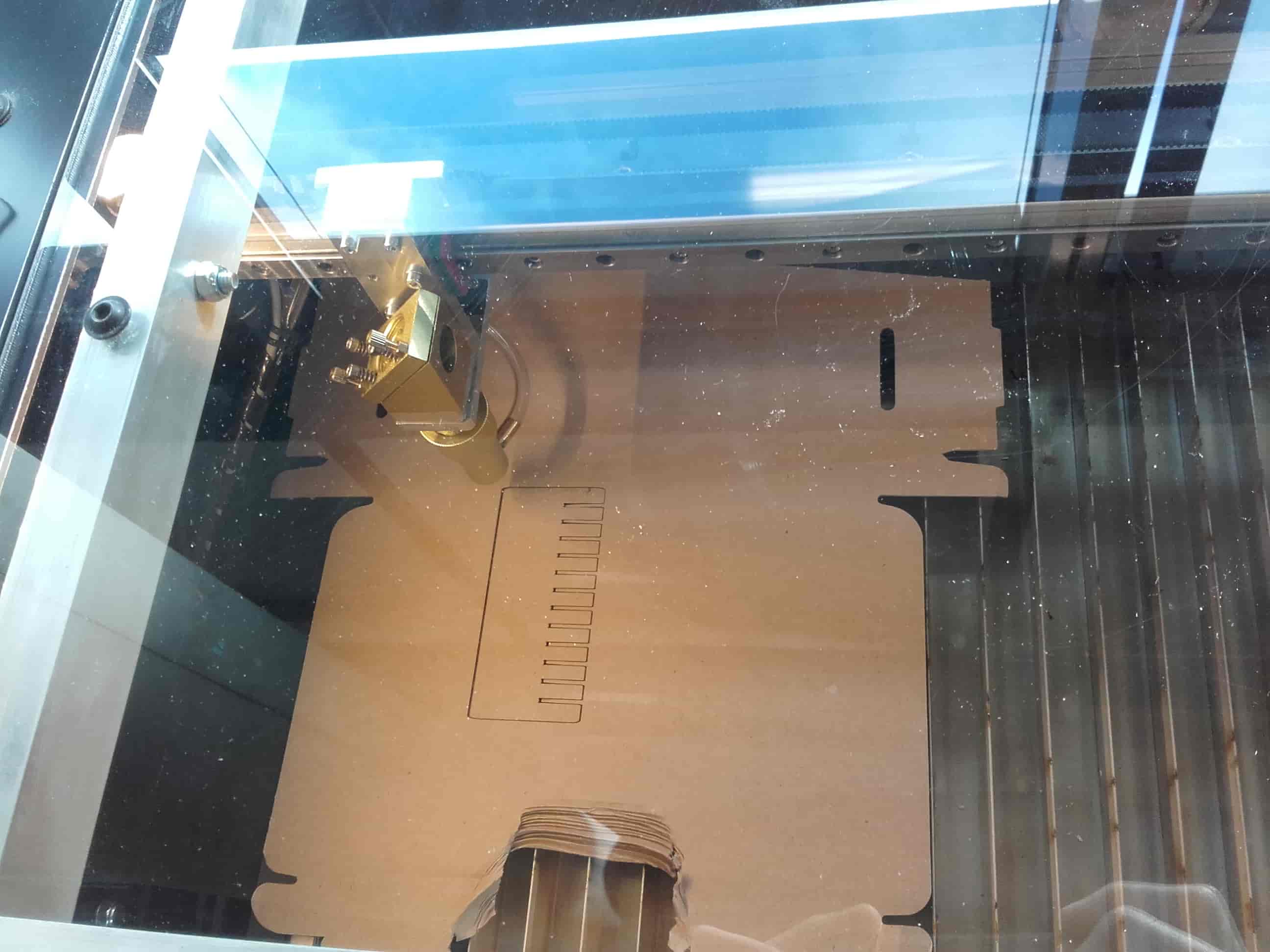
I was commissioned with the task of creating a comb-like part that could be used to characterize cuts for mechanically joined connections. So I got into SolidWorks and started modeling right away.
Creating a Sketch
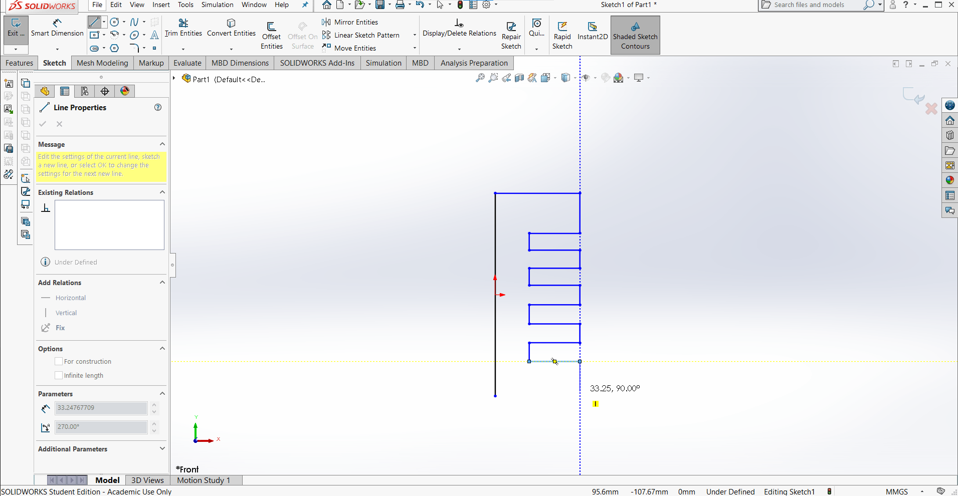
I decided to create 12 slots in the comb so I quickly sketched them in with the Line tool.
Adding Relations
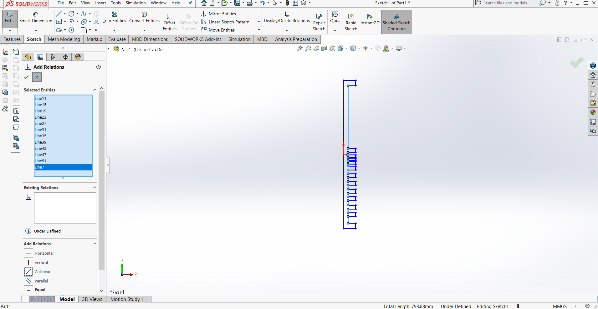
I added relations such as colinearity, equality and symmetricality wherever possible to reduce the amount of necessary dimensioning.
Dimensioning
And then I added the dimensions that were necessary to fully define the part.
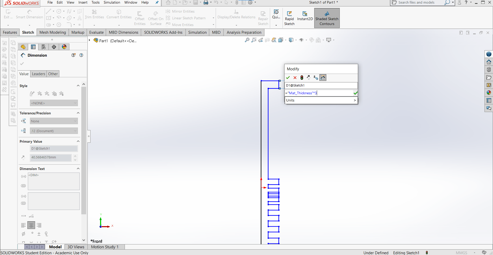
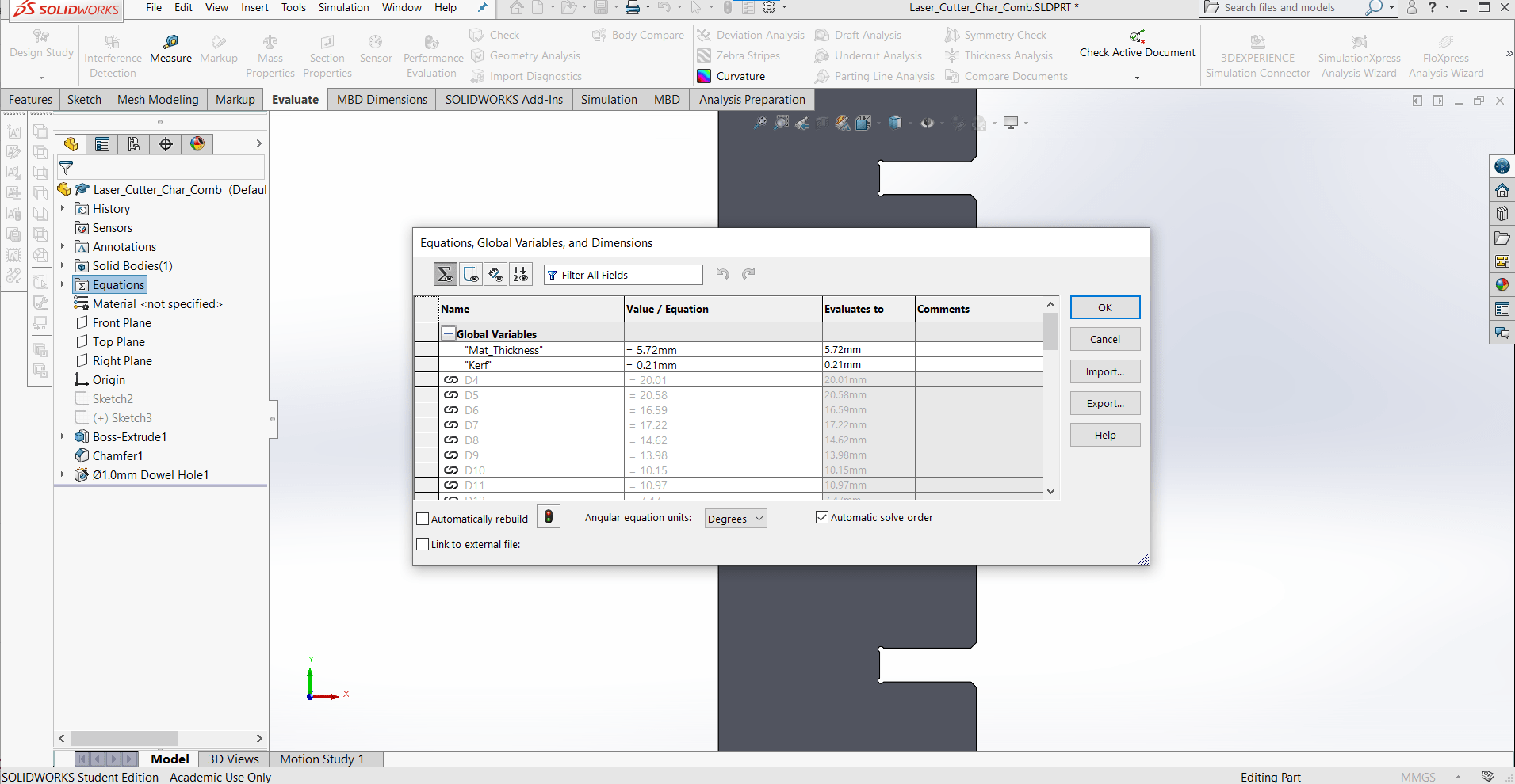
Parametric Design
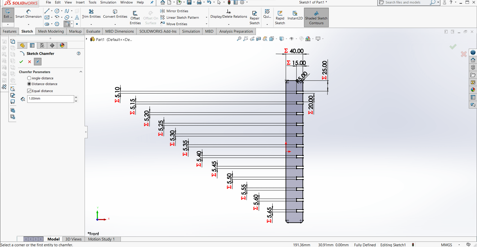
I only needed two global parameters for this model: "Mat_Thickness" and "Kerf". The slot width varies by 1/4th of the kerf, starting from the material thickness + 1/2 kerf and ending with the thickness + 13/4 kerf.
New Sketch
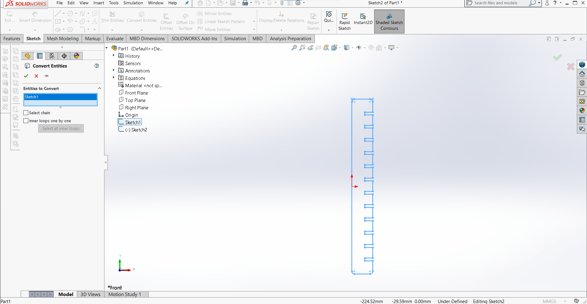
I didn't want to destroy any of the relations I had just created by adding details such as chamfers and inner corner radii, so I opened a new sketch and duplicated the first using the Convert Entities tool.
Adding Details
I added chamfers to assist with assembly and dog-bone radii for the inner corners (to relieve stress concentrations) to the new sketch.
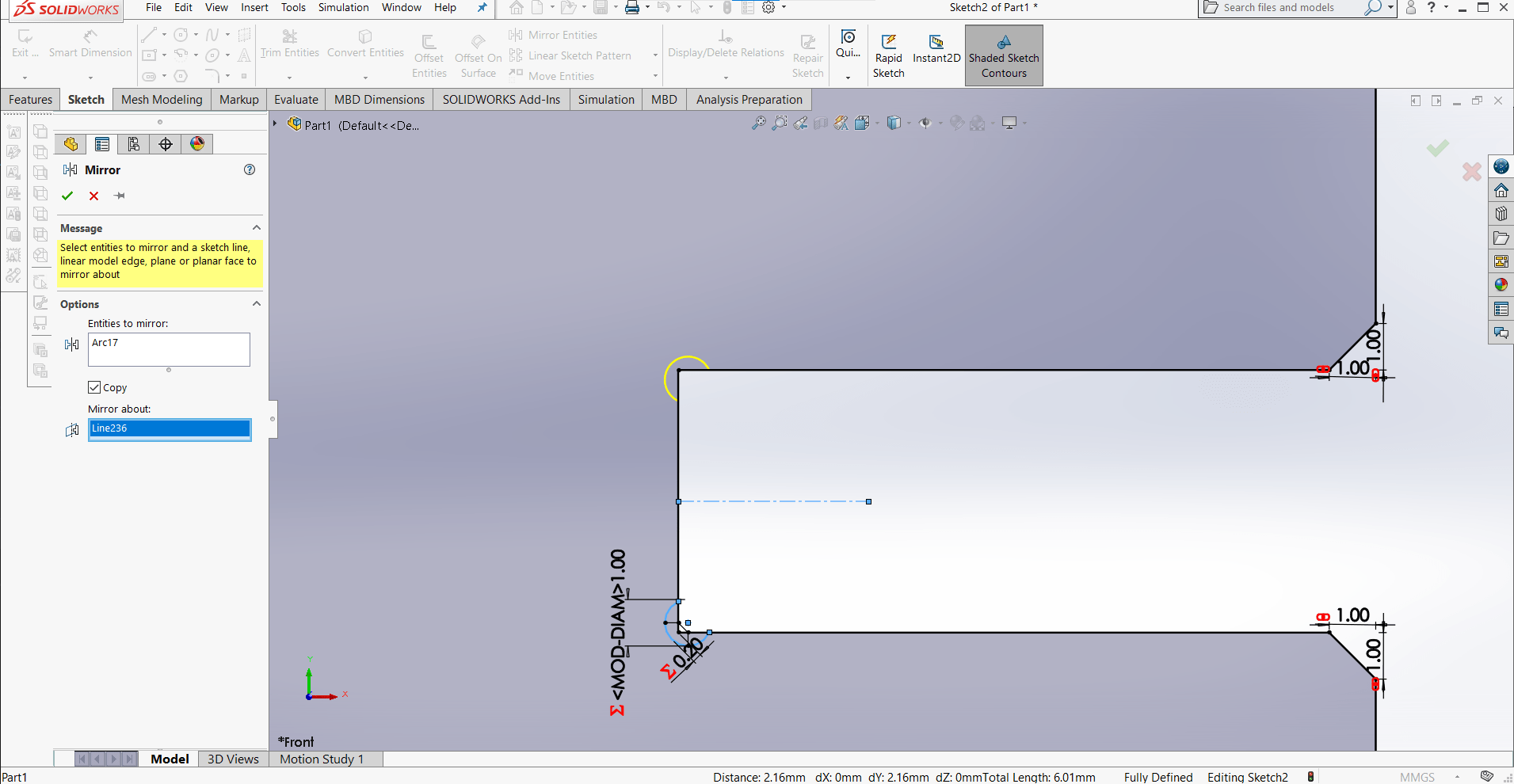
Mirror Tool
I defined the radius once, and then mirrored each one using the Mirror tool and Center Lines.
Trim Entities
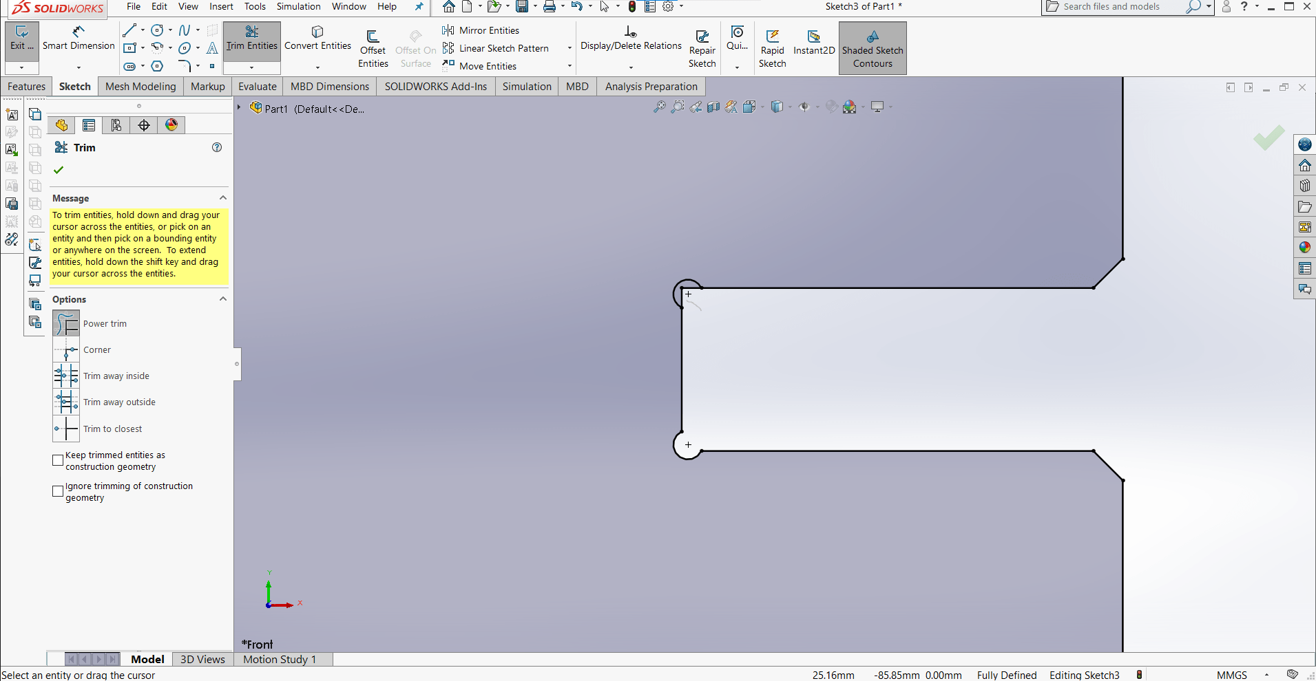
Then I just had to trim away the bits I didn't want using the Trim Entities tool.
Construction Lines
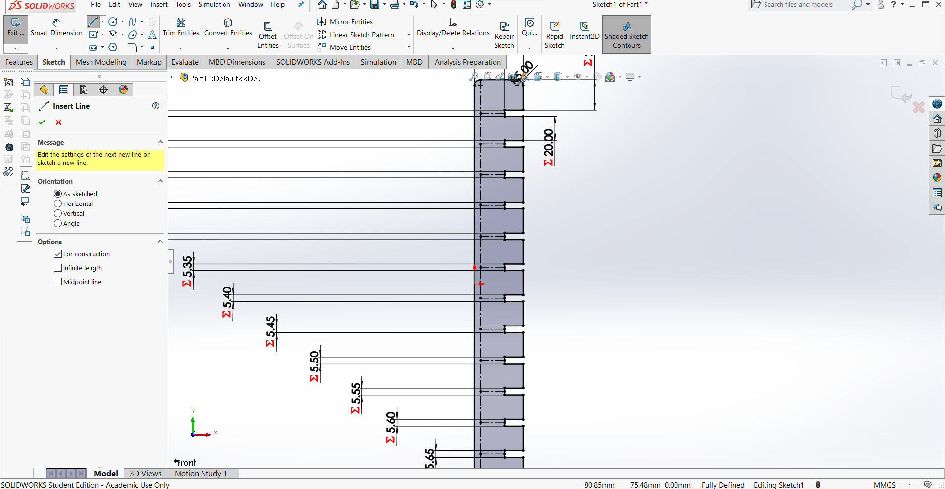
And inserted some contruction lines to help with the next step.
Text Sketch
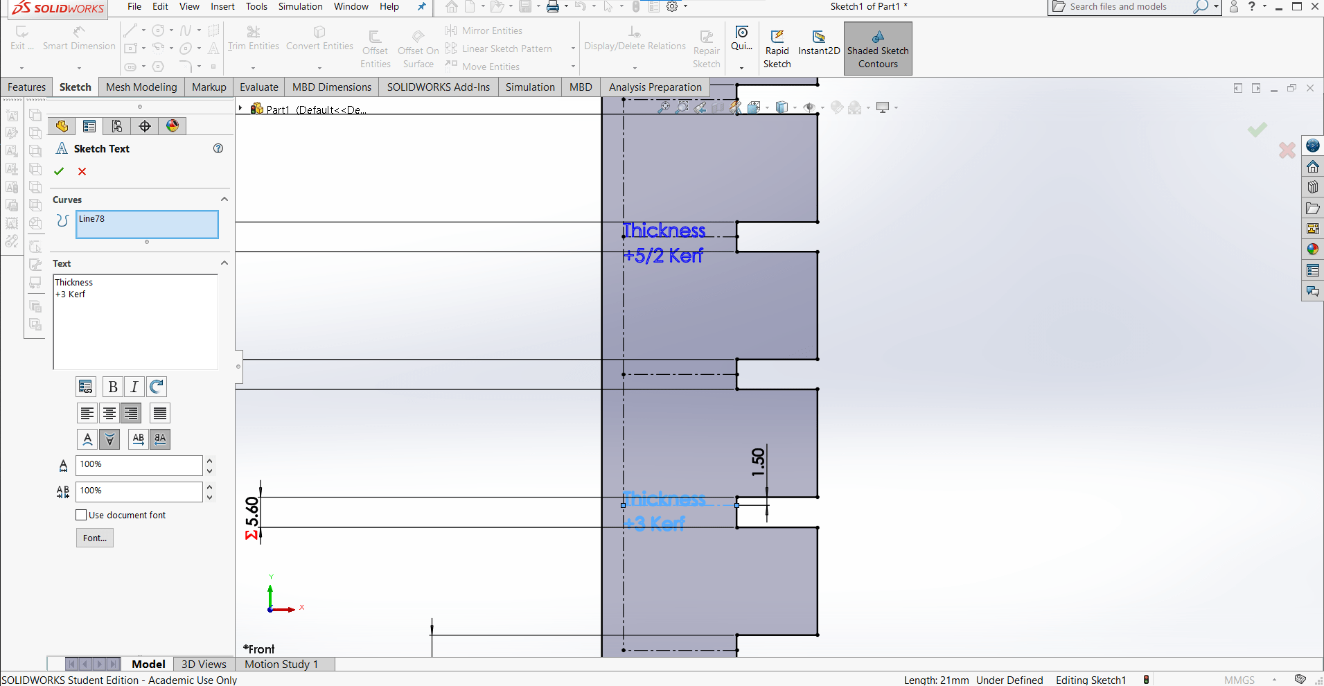
I thought it would be cool to engrave some labels for the comb so I added a new sketch and made them with the Sketch Text tool.
New Sketch
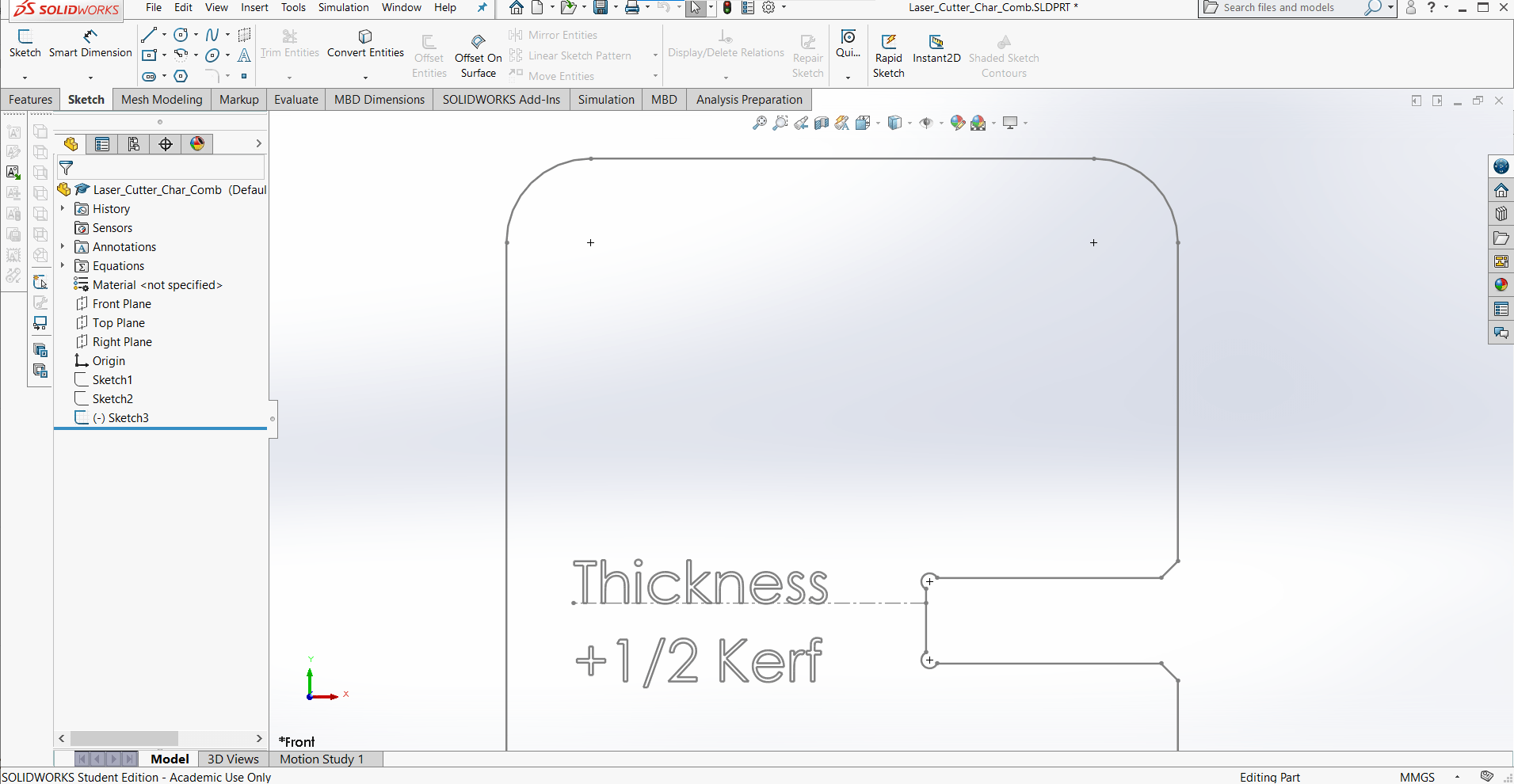
The details were all looking good so I thought I was ready to cut the part on the laser cutter.
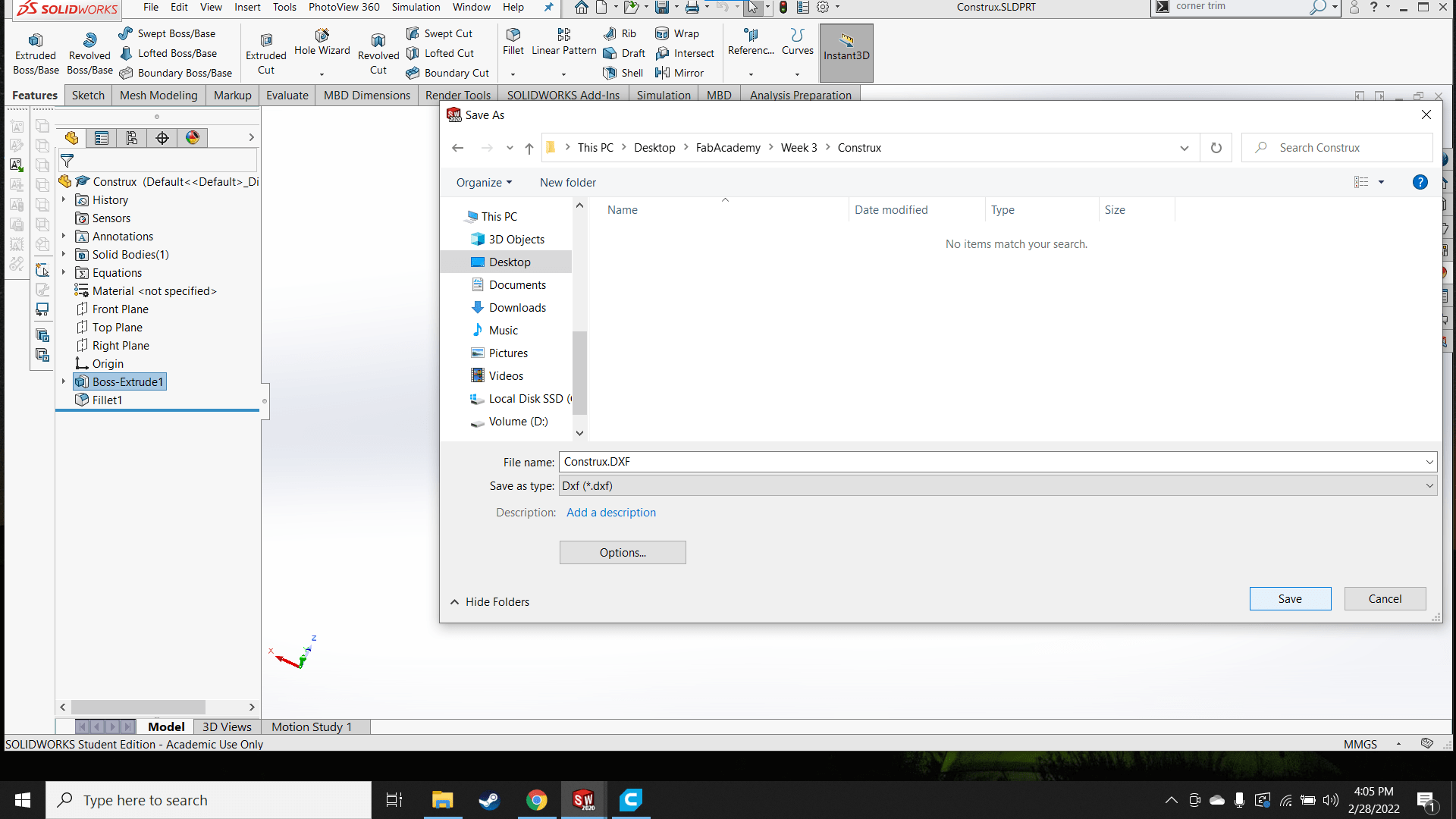
Save As
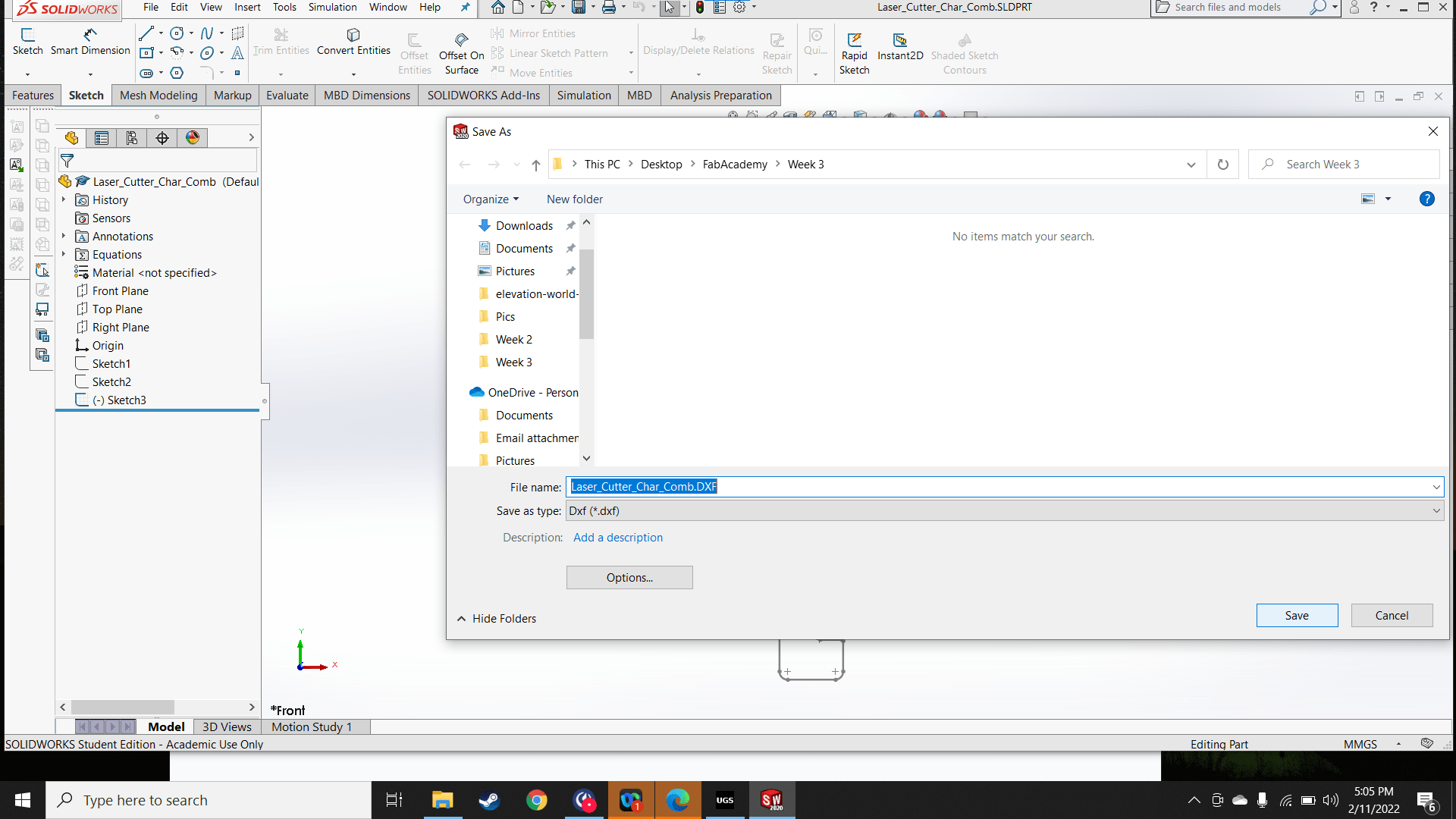
I exported the most detailed sketch as a DXF file.
Expert Warning
Roland has some experience with the laser cutter and with importing DXF files from SolidWorks. He said that for some reason, when opening this specific type of file, specifically from SolidWorks, the paths that are defined by the edges of the part are not connected. So, for example, a square does not import as a single path, but rather as four disconnected paths, which is too confusing for VisiCut to figure out, so it usually results in bad cuts or poor geometry (exactly what we do not want for this test part). It is possible to combine the nodes to create a single path in Inkscape, but it is tedious because by default the software only allows for manual combination of two nodes at a time. This simple part has hundreds of nodes so Roland suggested trying to open the file in Silhouette Studio first in the hopes that we might be able to generate a vector file with a connected path.
Check in Silhouette Studio
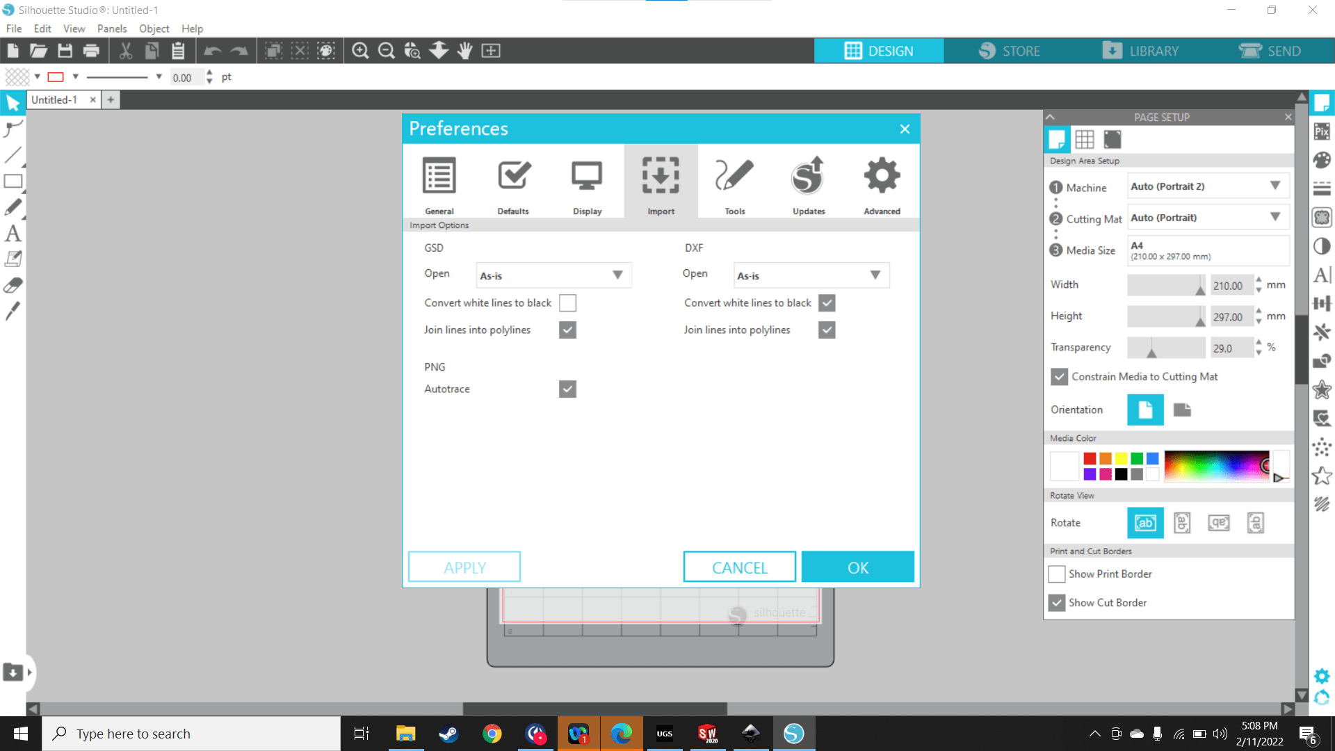
So I changed the import setting in Silhouette Studio to "Join lines into polylines" and then opened the part to give it a shot.
Not Gonna Work
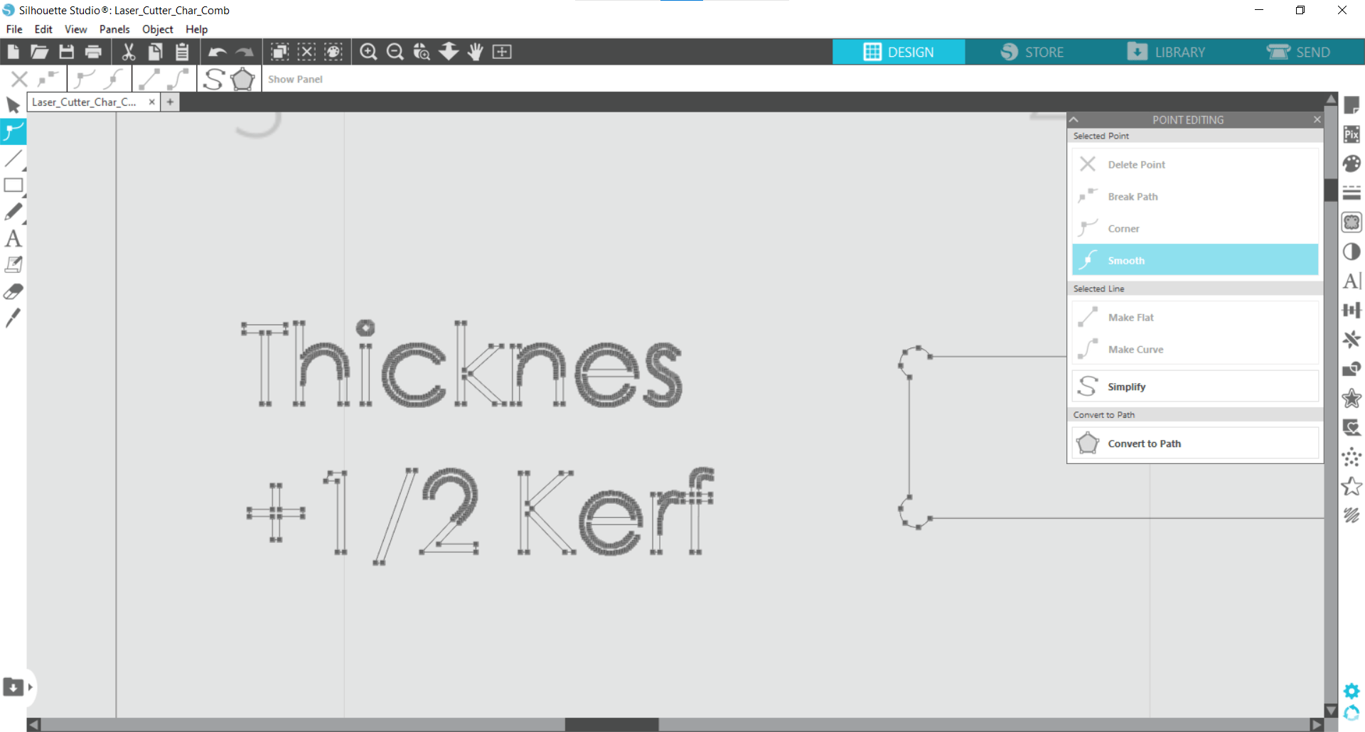
Not only could Silhouette not connect the nodes to create a single path, but it also made clear another problem I was not foreseeing. This is where I learned about single line fonts and that I couldn't simply use the default sketch font from SolidWorks for engraving.
Yet Another Mistake
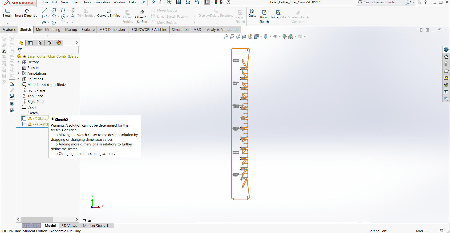
Reopening the part in SolidWorks revealed yet another mistake. Duplicating sketches using the Convert Entity tool can be problematic when changing parameters, especially when there are chains of sketches that are copies of others, as I had done in my initial, hasty design. The sketches blew up when I changed the parameters.
Boss Extrude
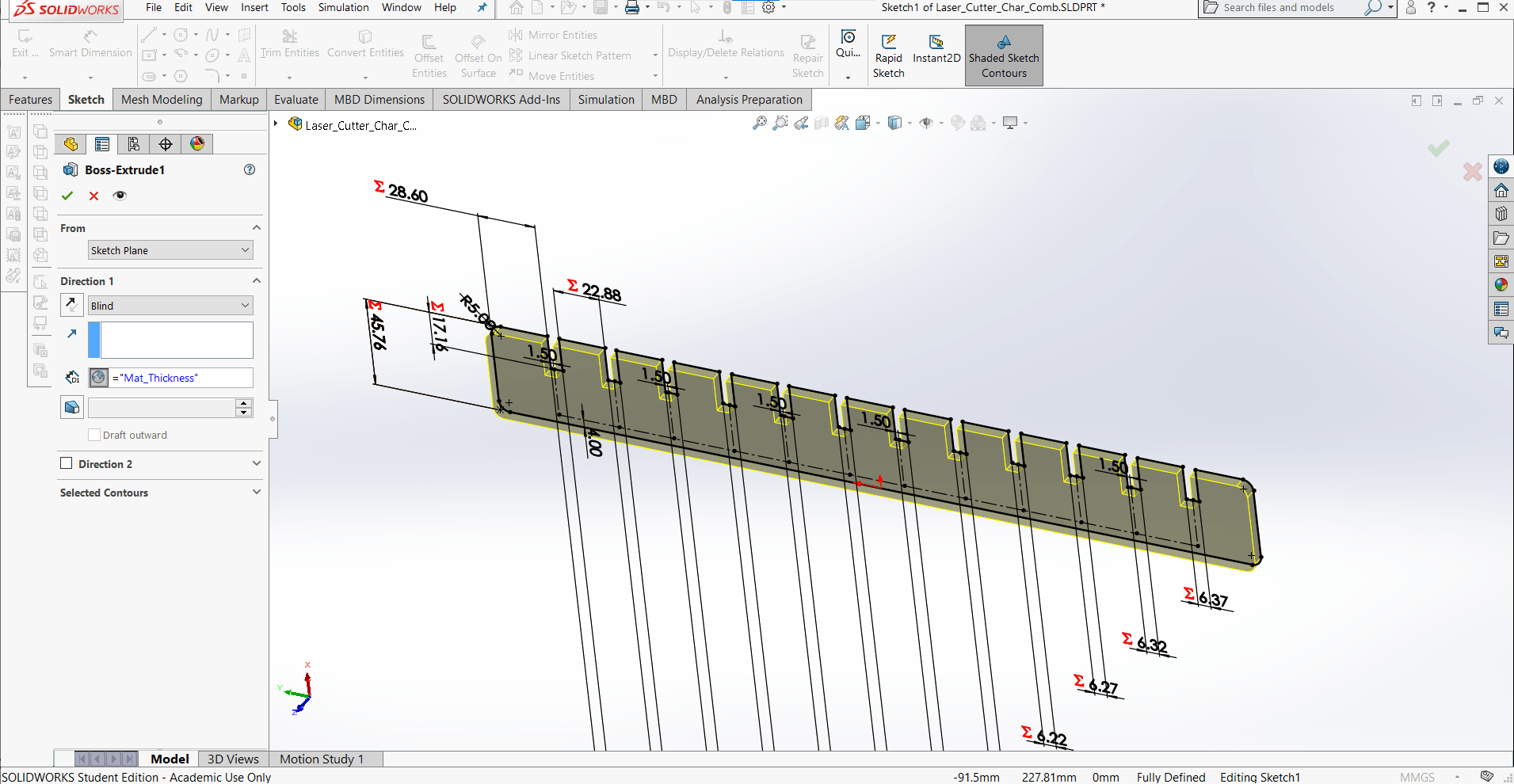
So I decided to make the part properly, using features instead of only sketch tools. That process began with extruding the part into the third dimension with the Boss Extrude tool. The size of the extrude is defined by the material thickness variable.
Chamfers
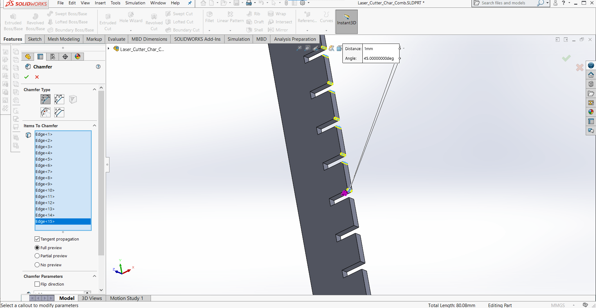
I added the chamfers using the Chamfer feature.
Inner Corner Radii
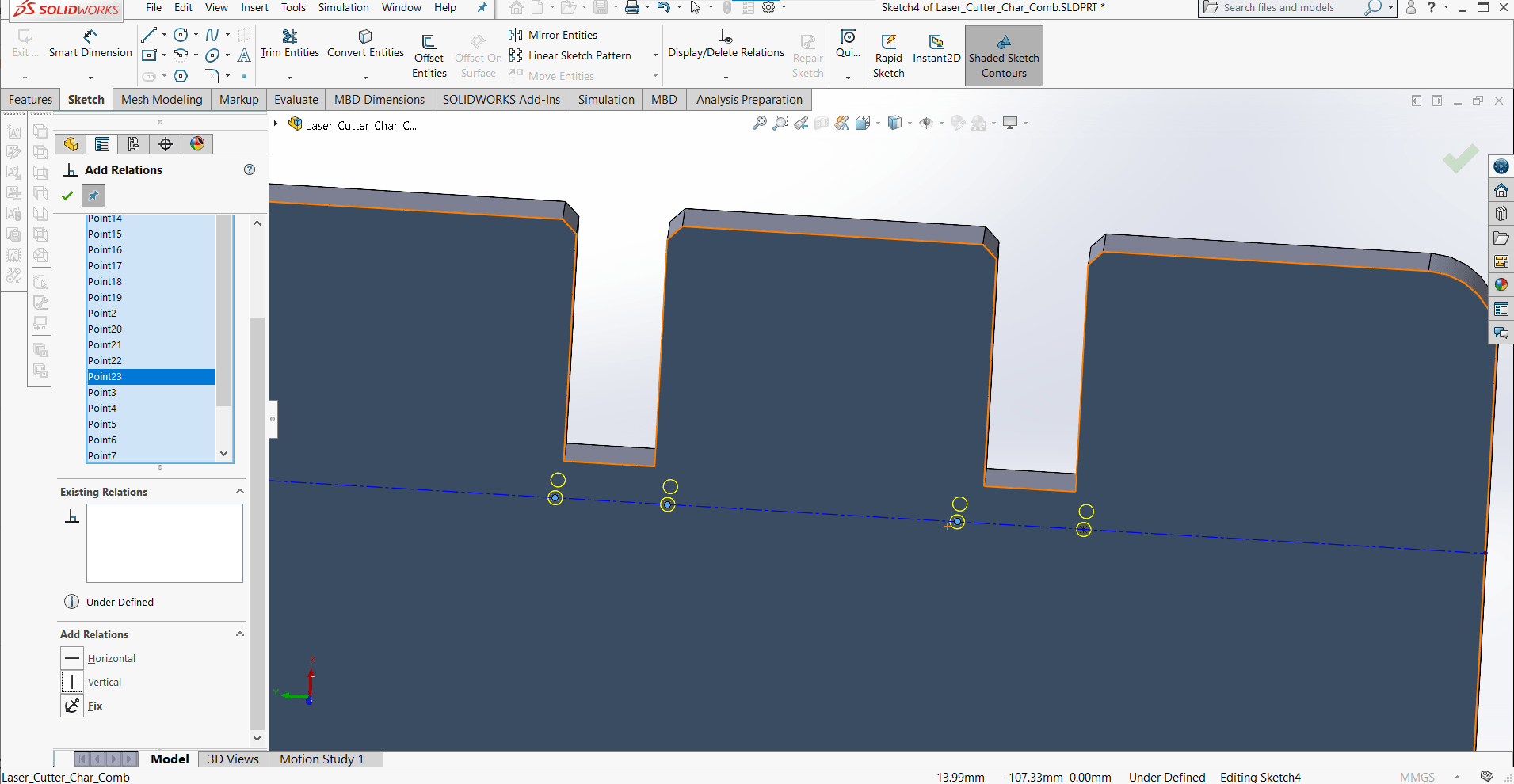
And I added the dogbones for the inner corners using the Hole Wizard.
Dimensioning
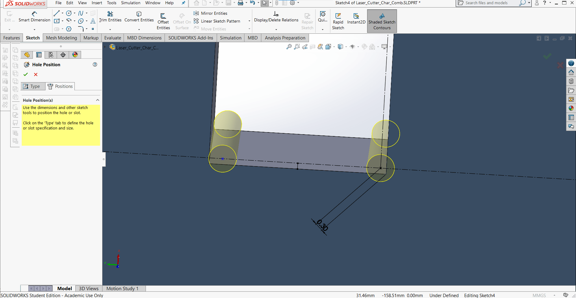
Just like before, I defined the position of one hole.
Symmetry
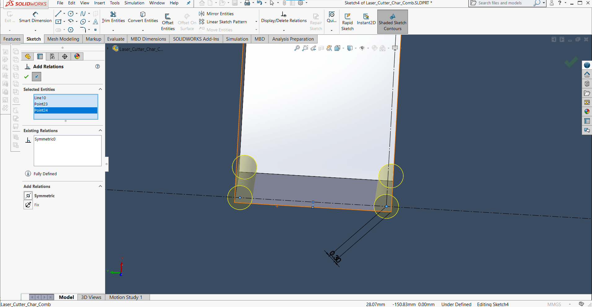
And then used a Symmetric relation to define the rest via construction geometry.
Same Geometry
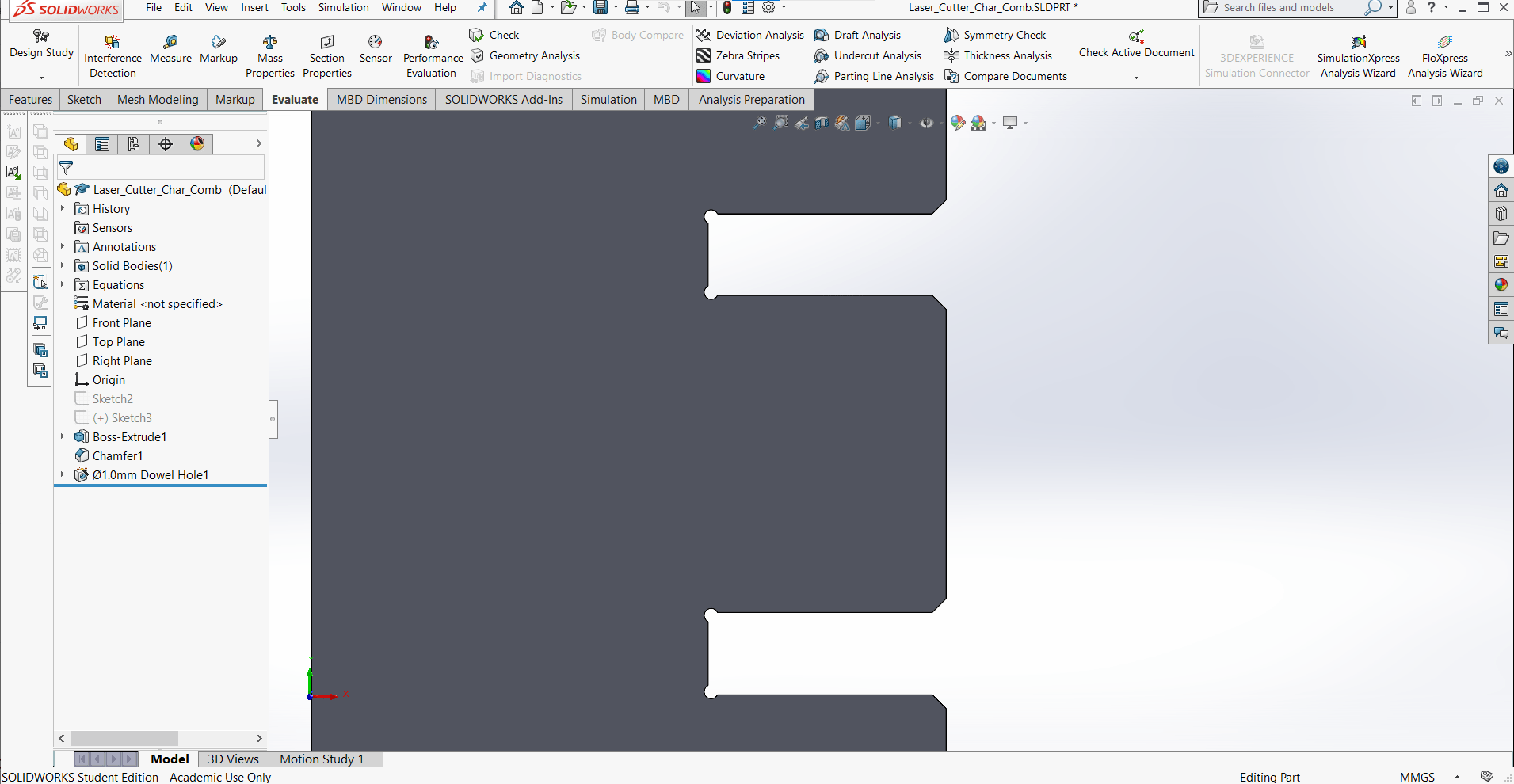
I decided to add the text later in Inkscape, but my part had the same geometry as before.
Success
And now I could change the parameters at will without destroying the part. Success!
New DXF File
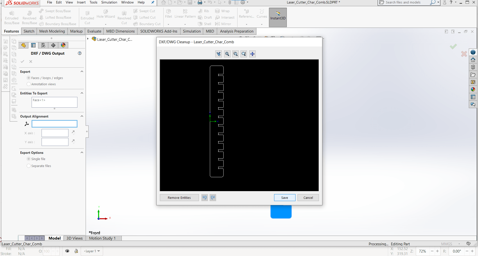
I was finally ready to export the DXF again, and this time I had a trick up my sleeve...
FOSS for the Win
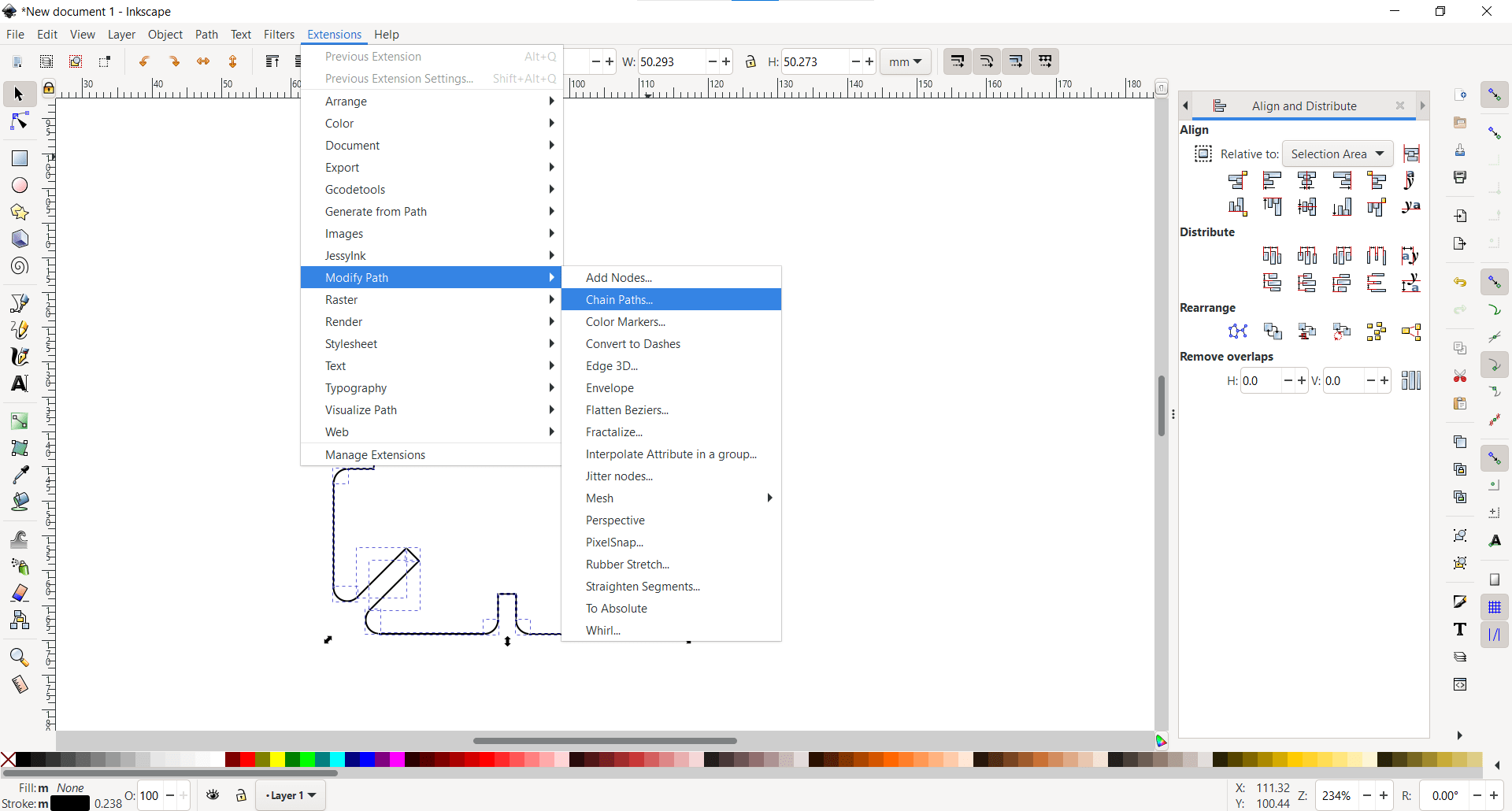
The most wonderful thing about open source software is the abundance of tools and help that exists out there. I discovered an extension for Inkscape called Chain Paths and an excellent little guide for how to use it.
Select Separate Paths
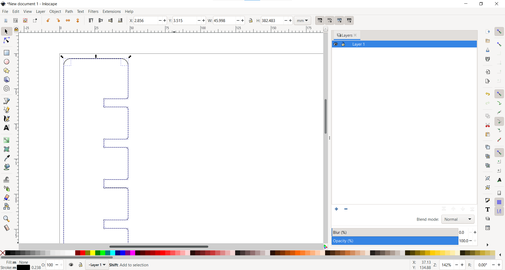
I selected all of the separate paths for the cut using Ctrl.
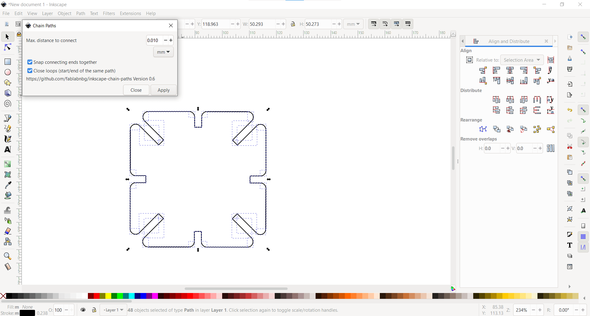
Chain Paths
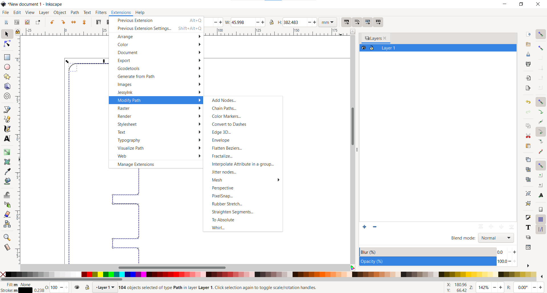
And then used the new Chain Paths extention to open the Chain Paths dialogue box.
Apply
And then clicked apply and close.
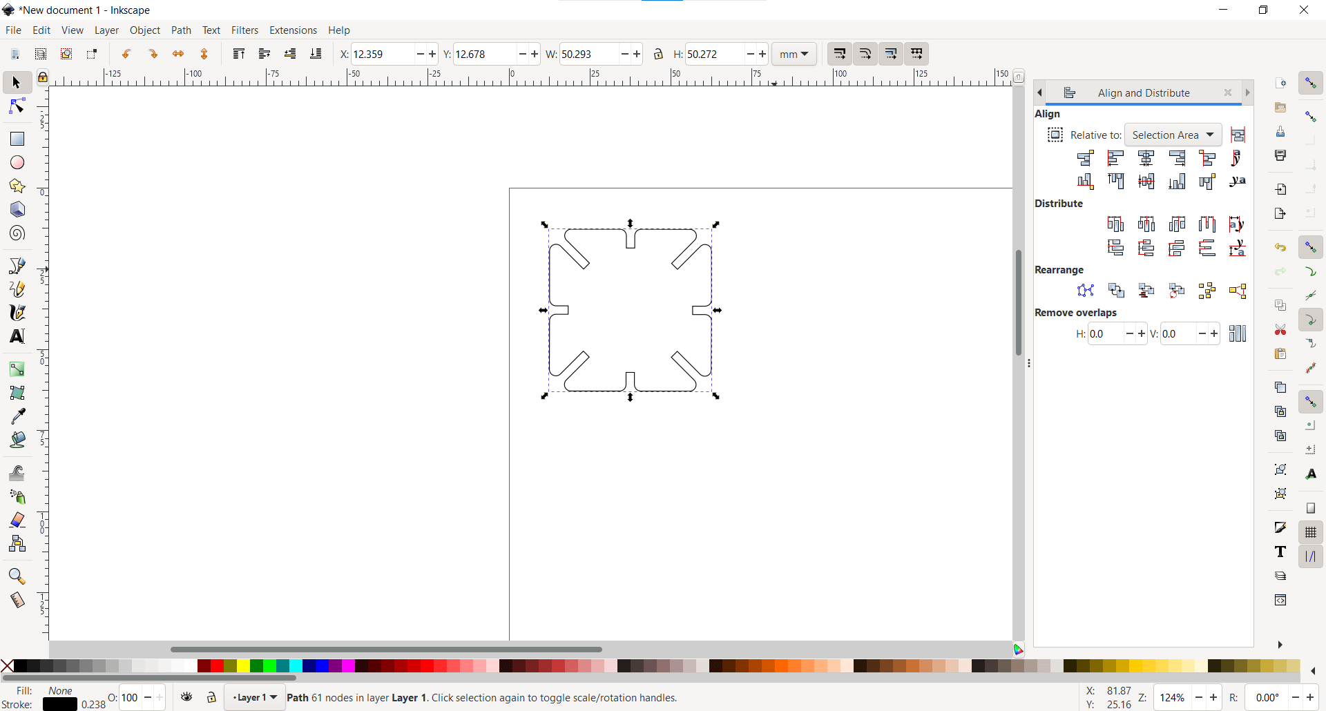
Error
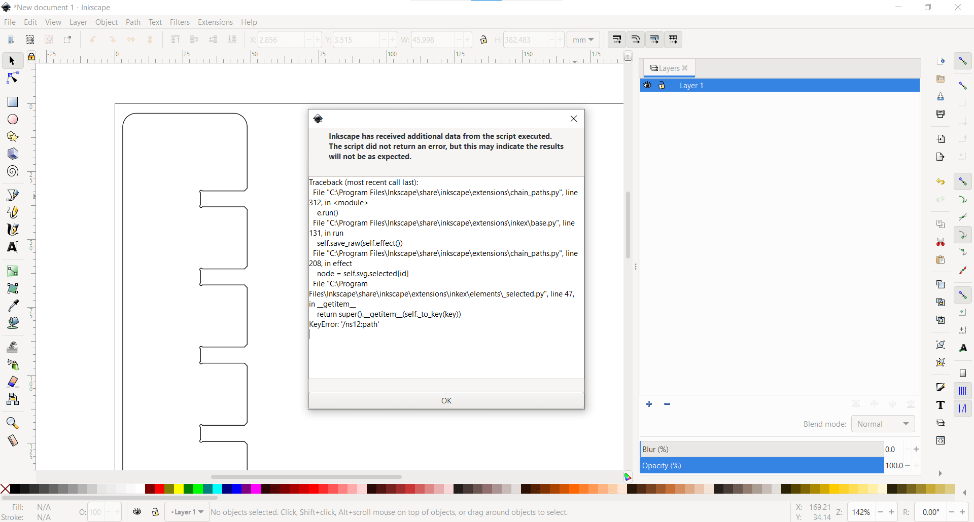
I did get an error upon applying, but it doesn't seem to have caused any problems. I finally have a single path to cut my entire part. I saved it as an SVG file, and then opened up VisiCut once again.
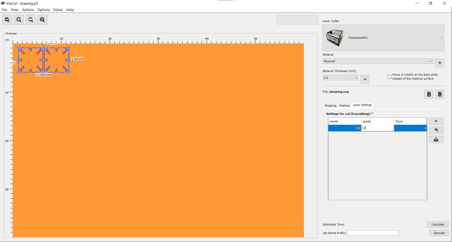
New Material
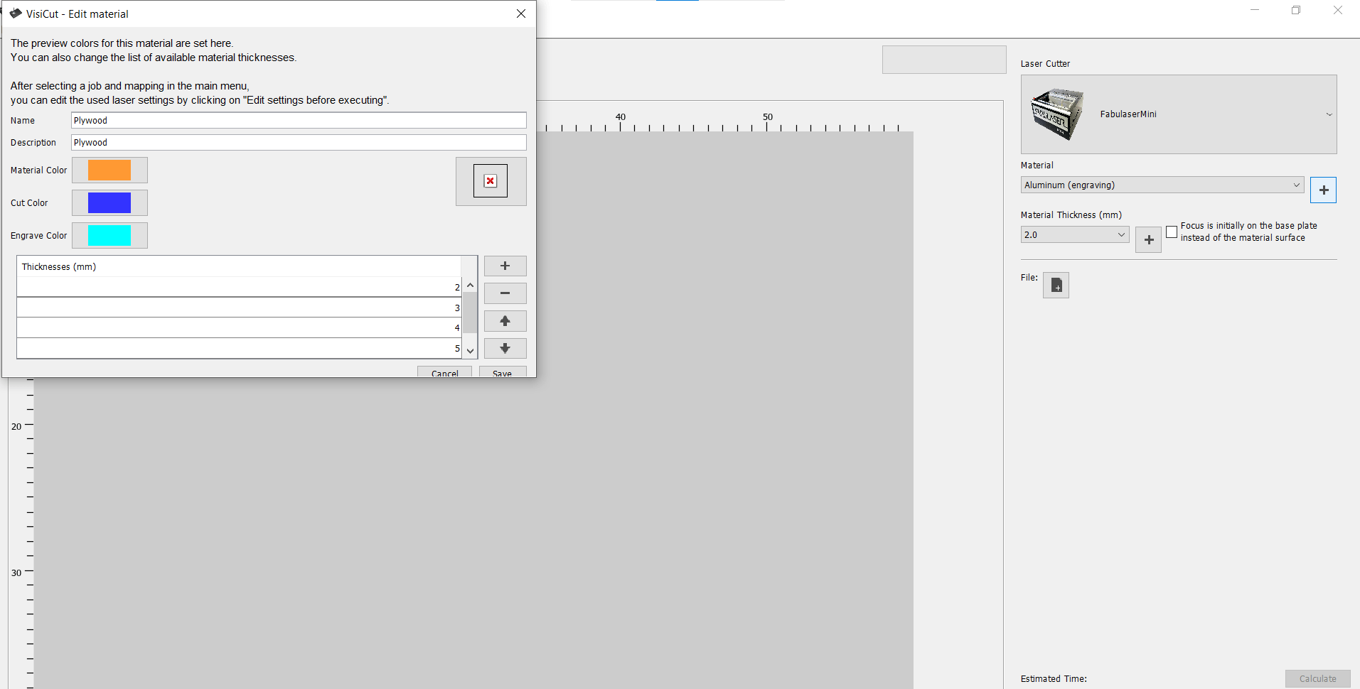
I started by making a new material for the Fabulaser Mini. I called the material "Plywood" and gave it the same properties as MDF.
New Thickness
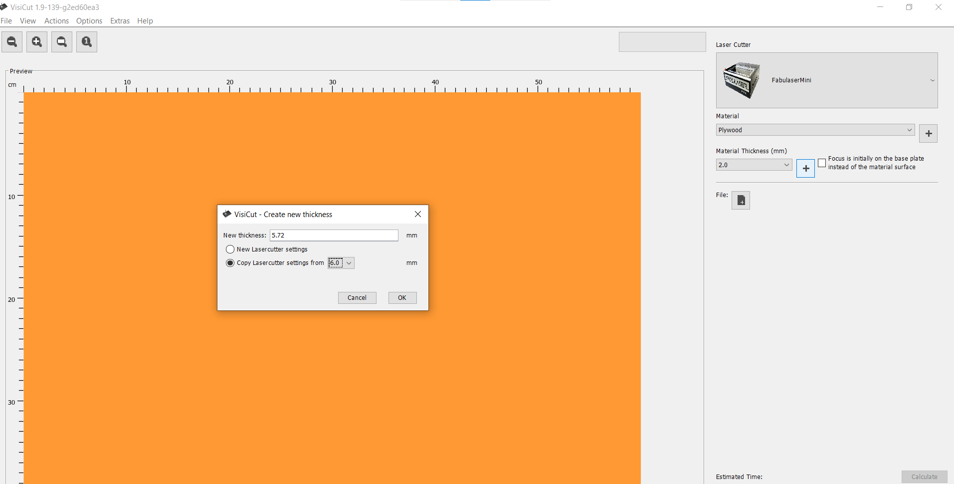
I also changed the material thickness to the thickness we measured.
Import New SVG
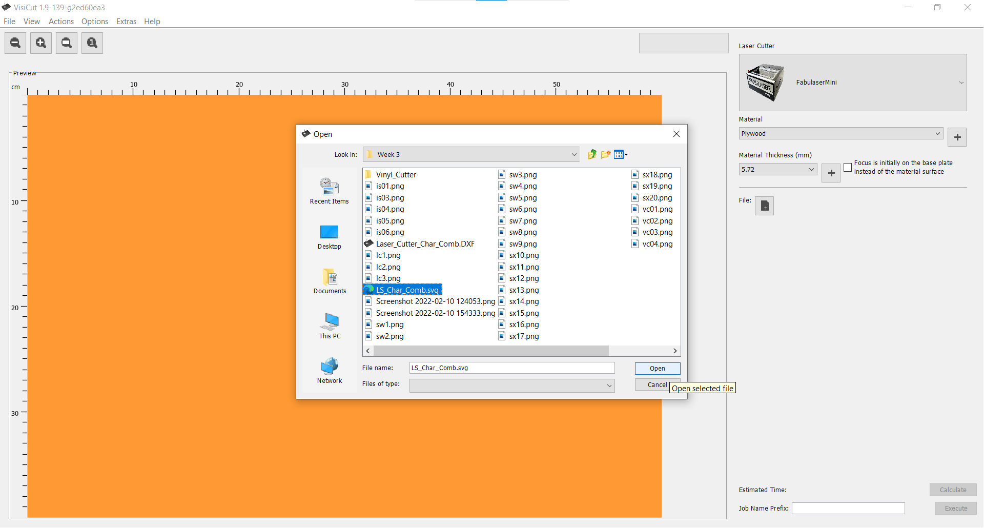
And finally opened my part.
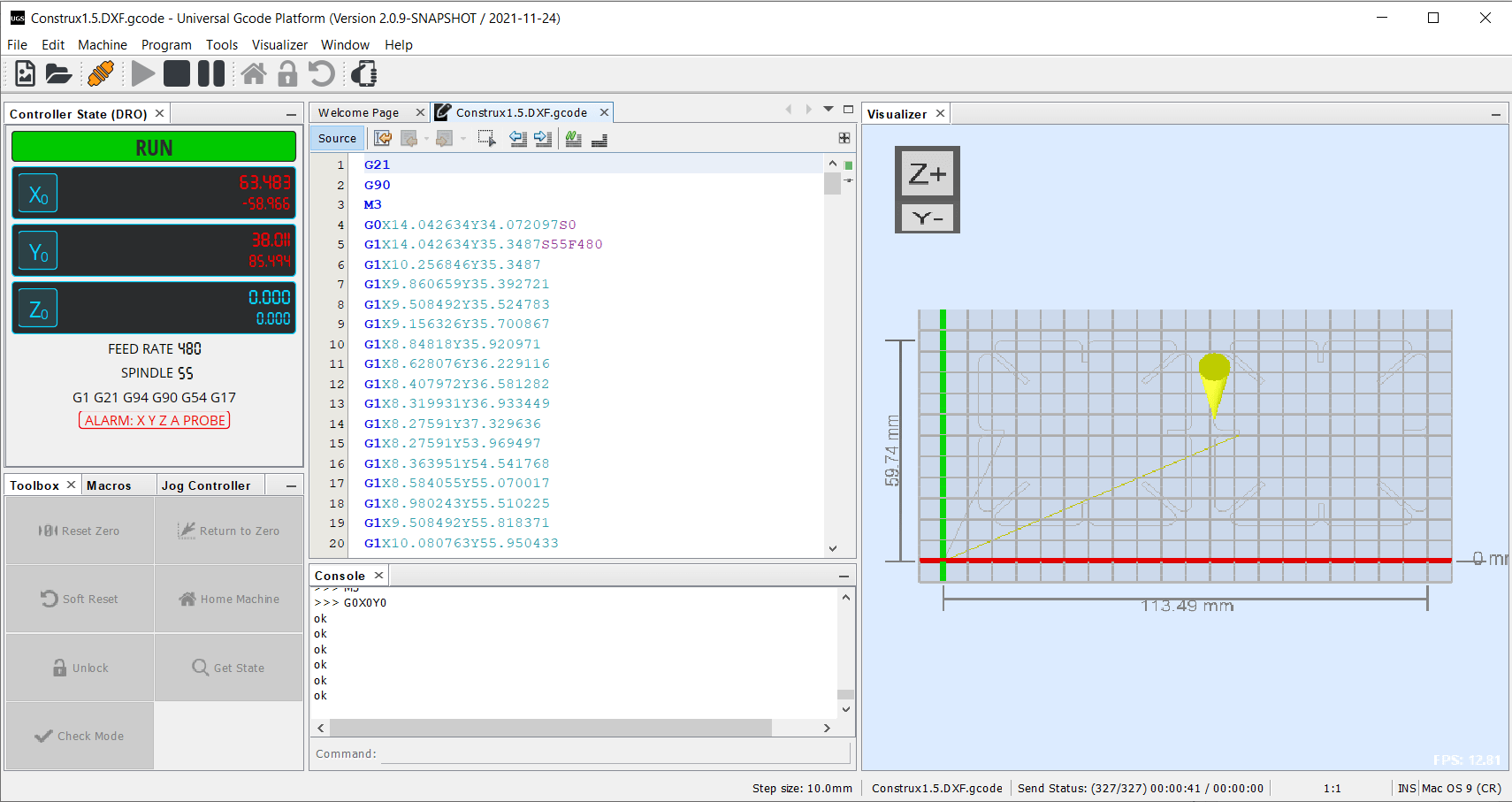
Scaled Test
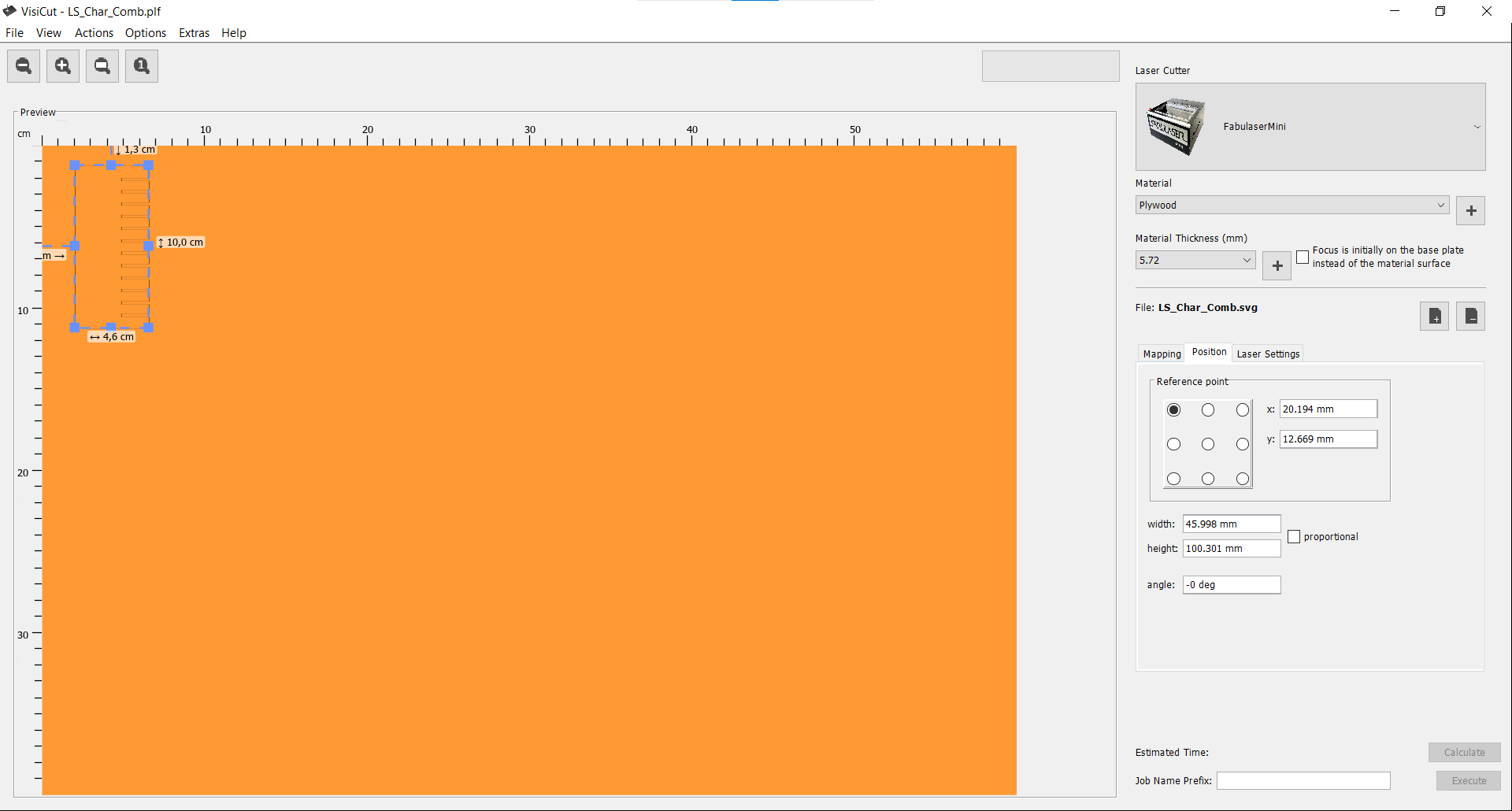
I wanted to test that I could actually make the laser cutter cut first, so I scaled the part to a smaller size to cut from cardboard and exported the gcode.
Universal Gcode Platform
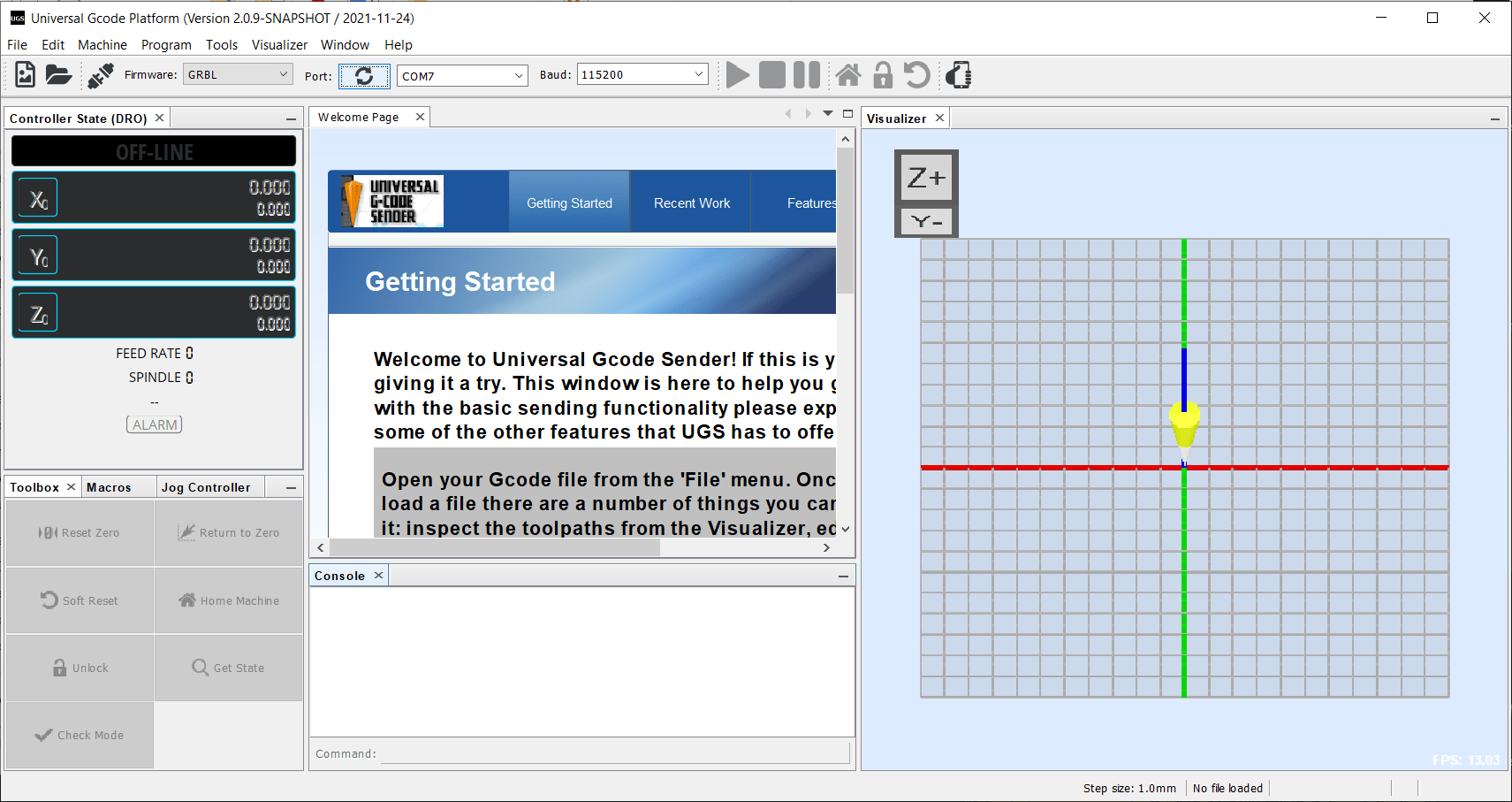
Now that I had gcode, I needed a program to stream it to the laser cutter so I downloaded and installed Universal Gcode Sender (UGS).
Open
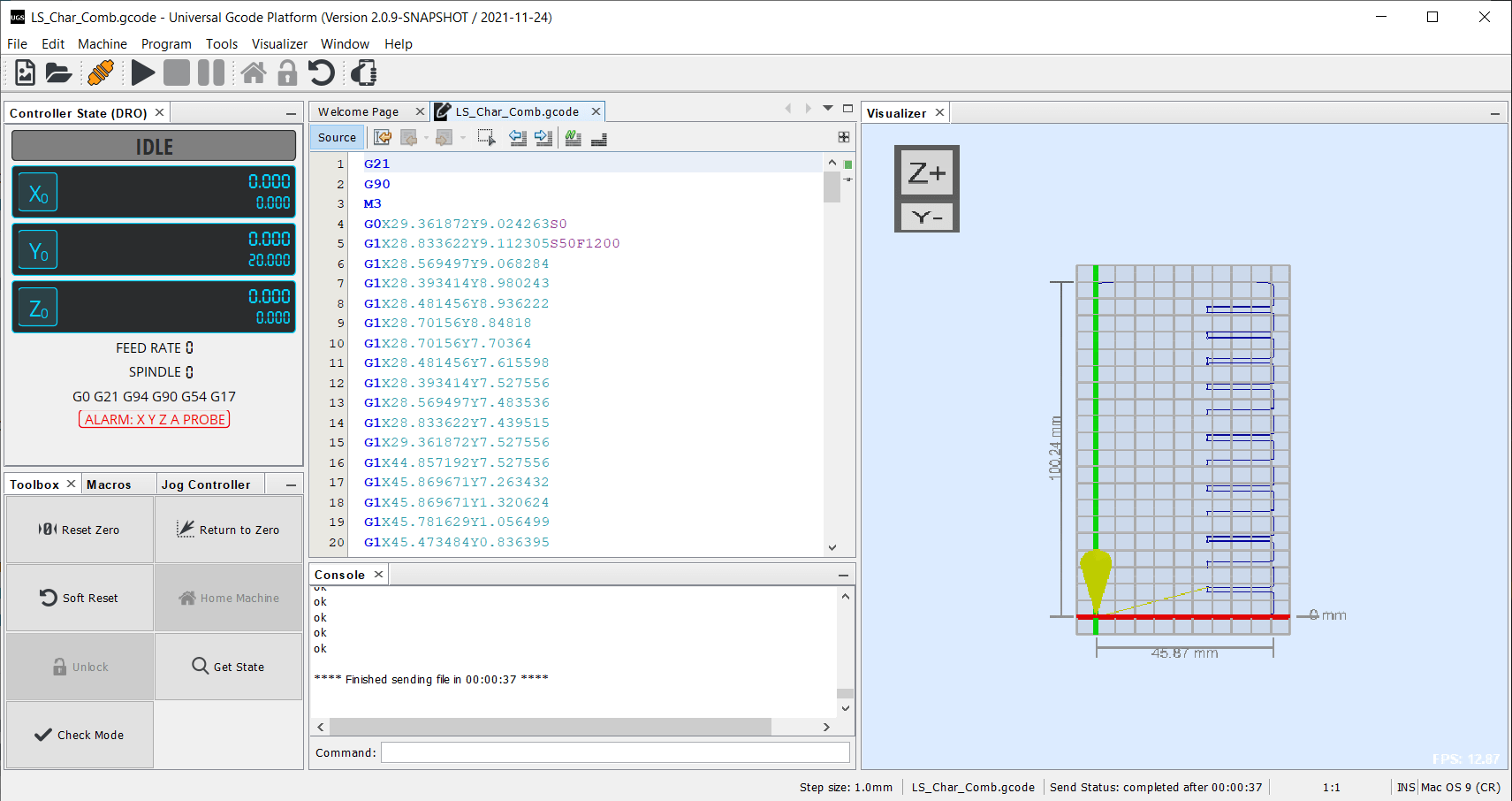
And opened the gcode for the scaled comb.
Prepping the Material
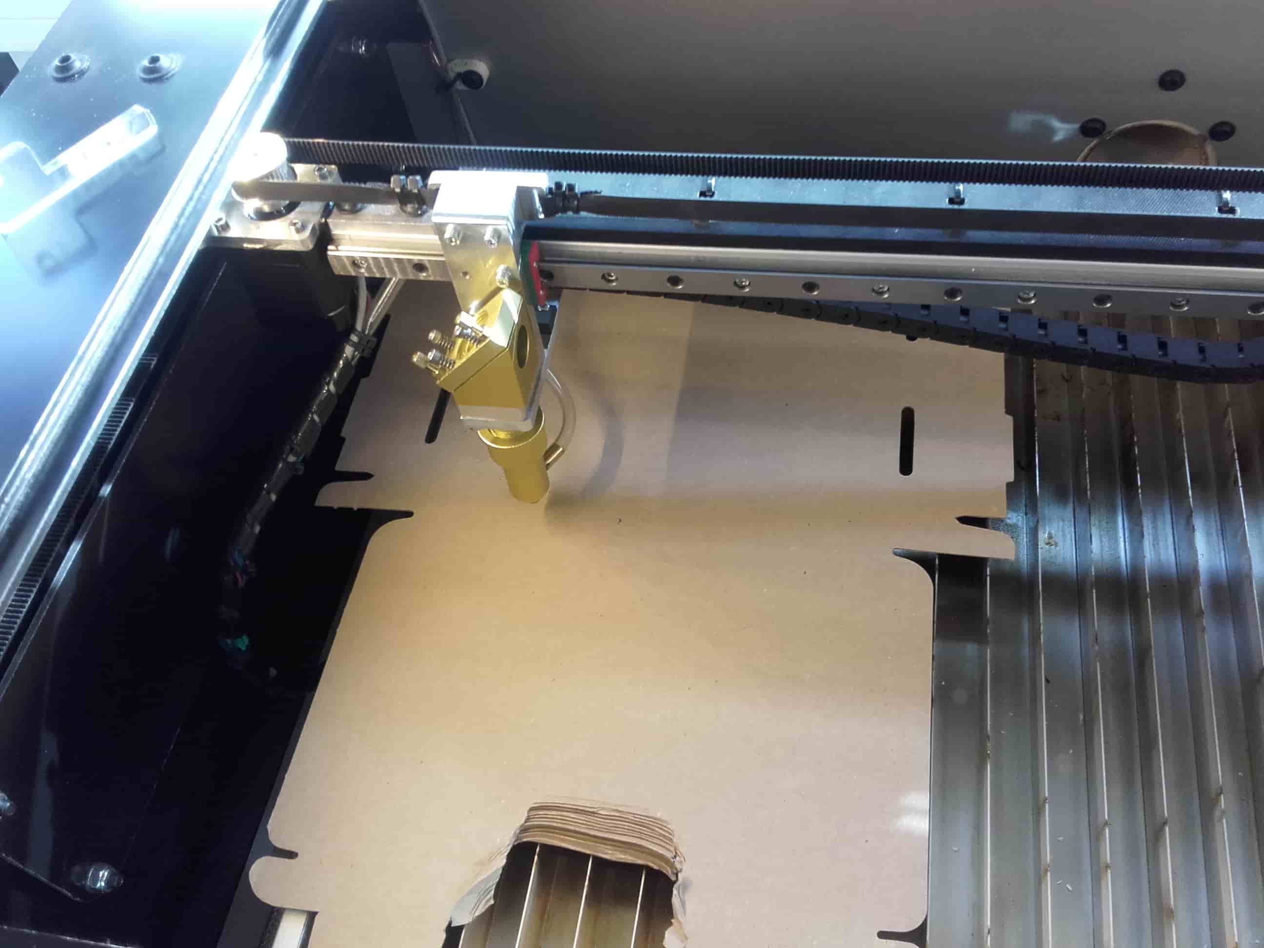
I added some cardboard to the laser cutter...
1st Time Laser Cutting
...pressed play in UGS, and then watched my first part being cut on the laser cutter with a very satisfied look on my face. 😎
Back to Inkscape
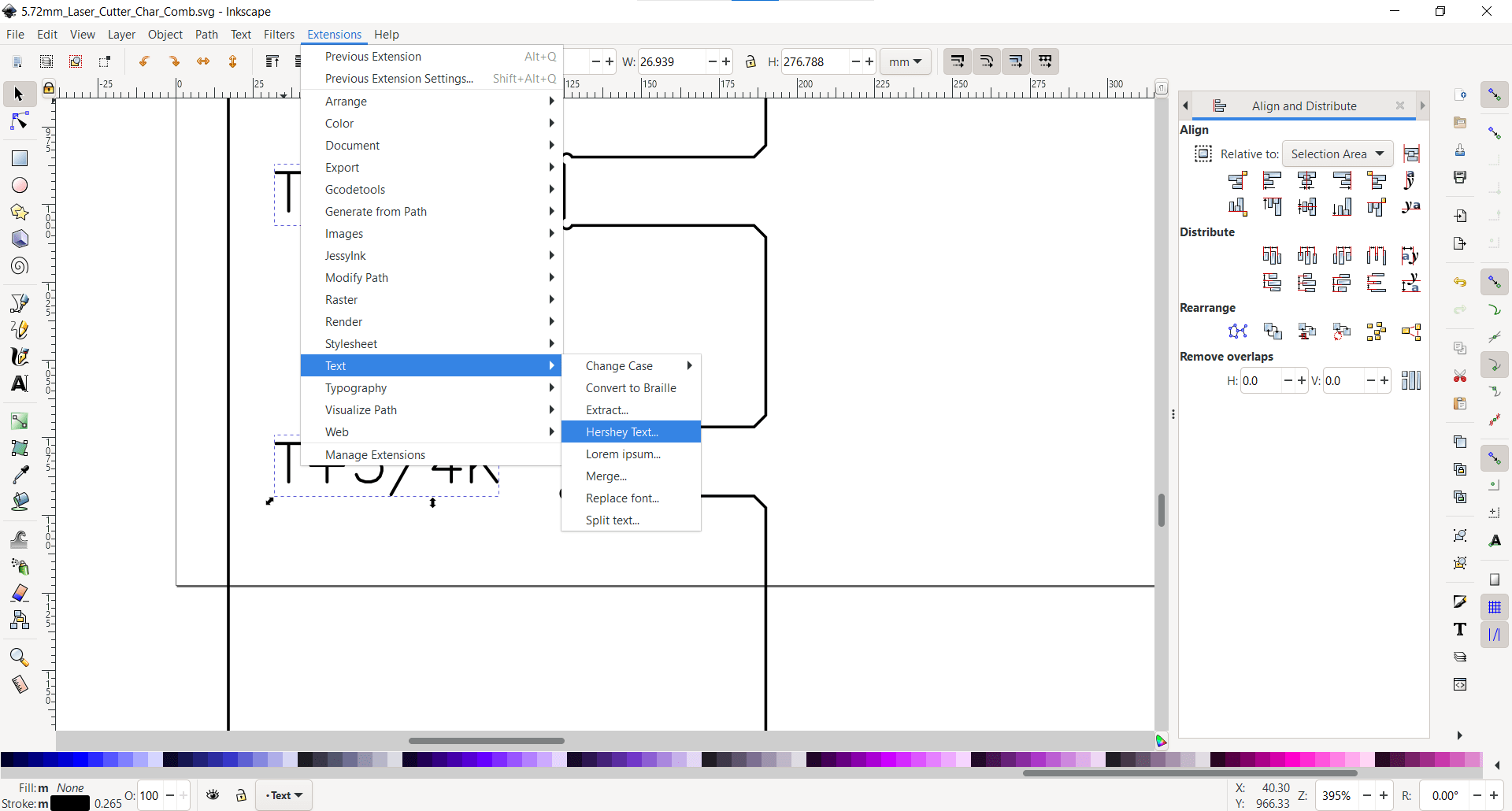
Then I went back into Inkscape and added the text I originally wanted to include, but this time using a single line font.
Wood Cutting
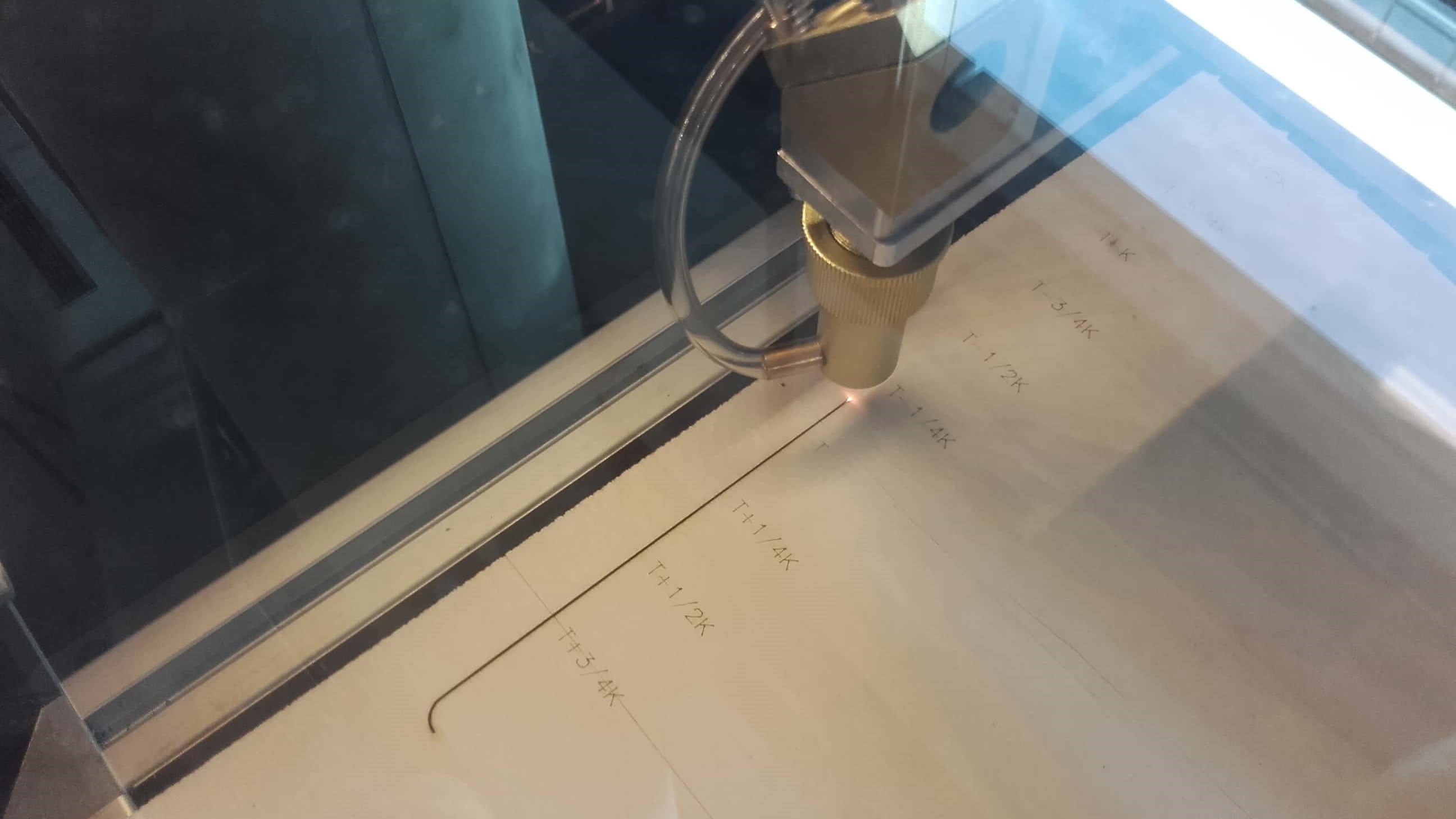
After the successful test with cardboard, I made the gcode for the full size part to test the joint fits for the 5.72 mm plywood we have in the lab.
Success
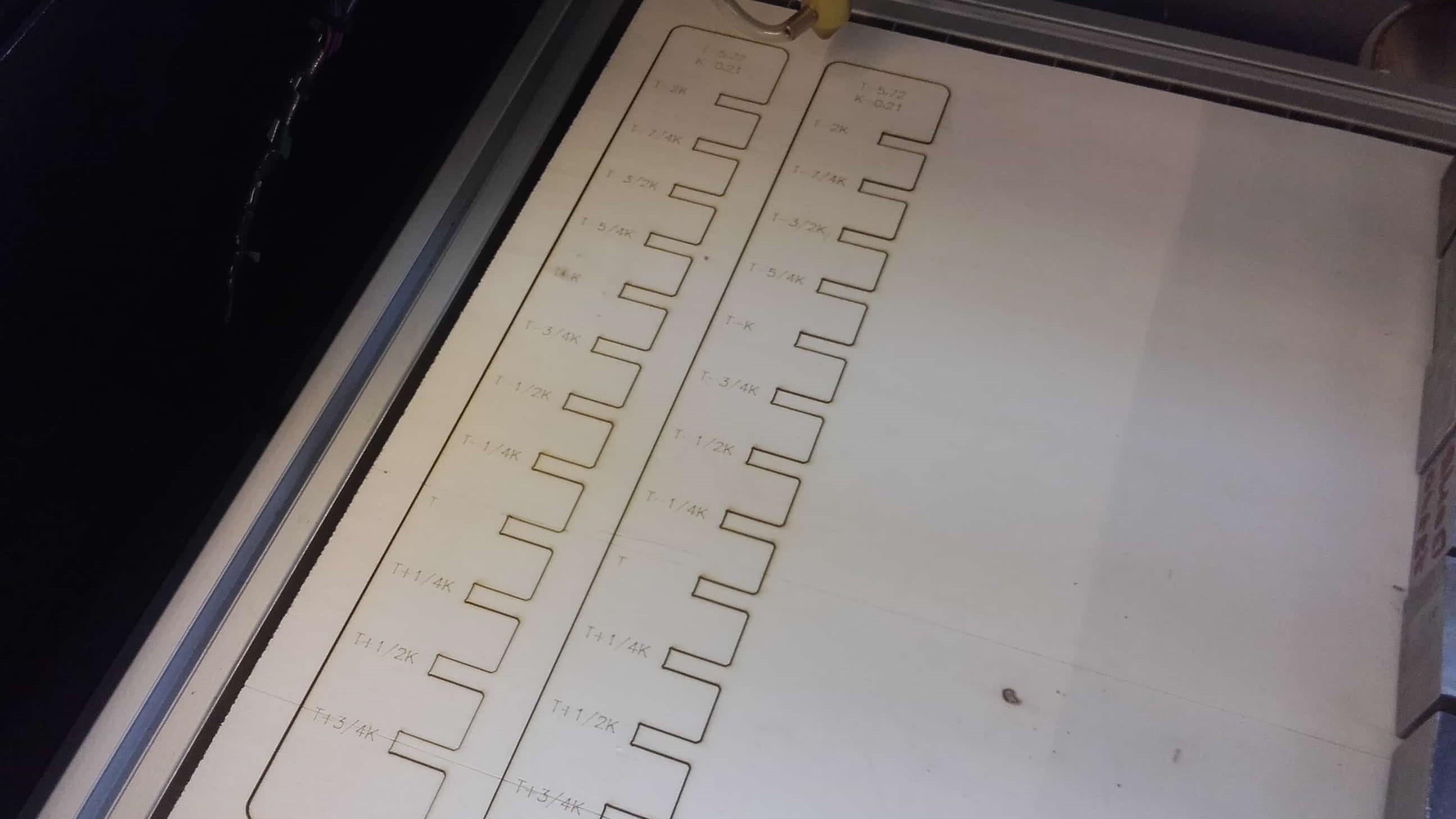
They turned out great!
Using the Combs
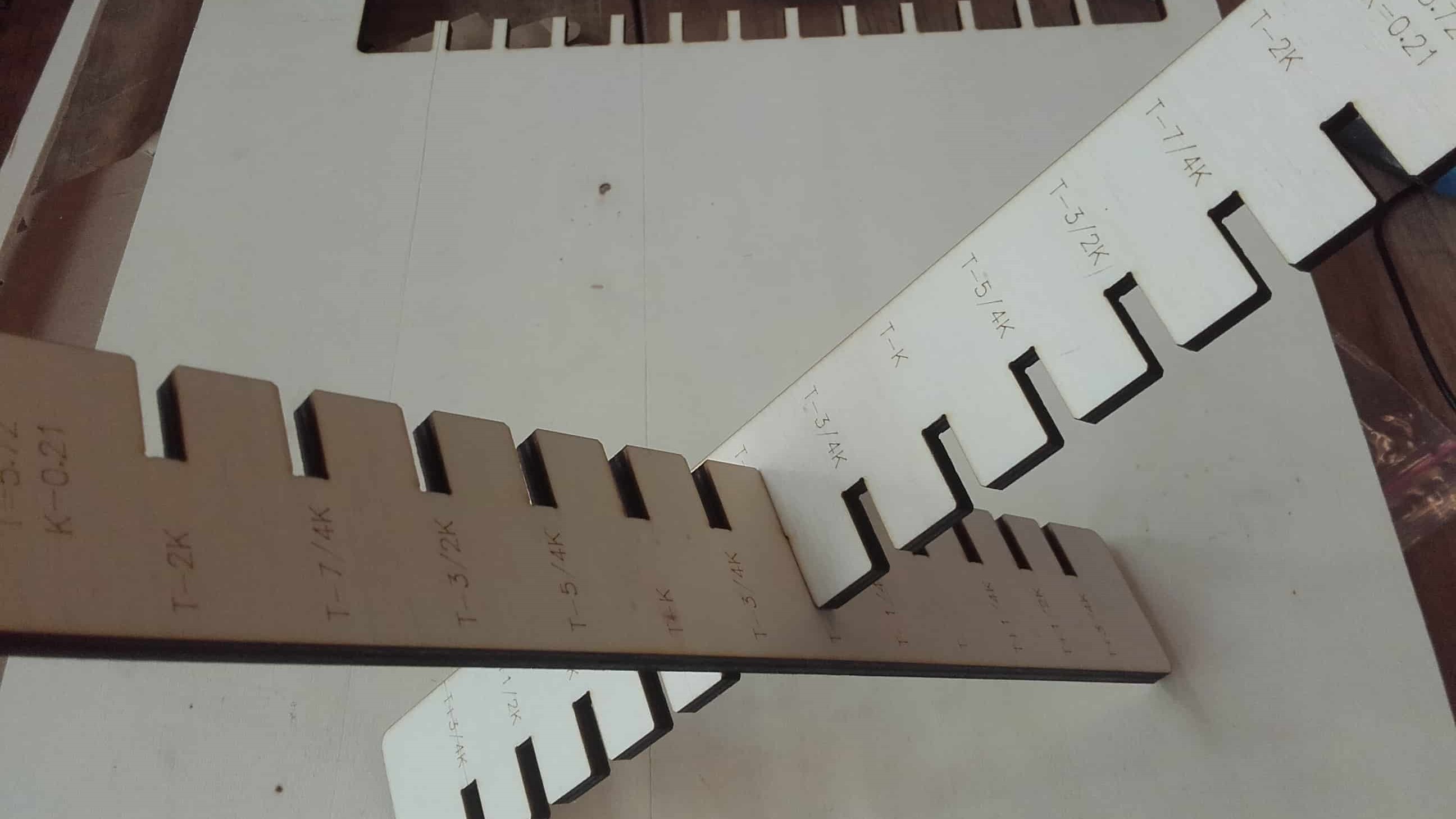
Once they were cut, we could finally use them to guage the joint fittings for the plywood material.
Recording Test Data
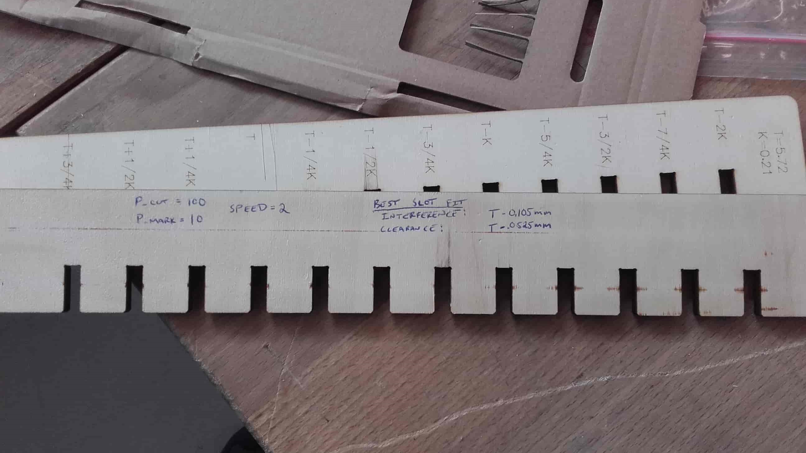
We recorded our data right on the combs to be compiled later for different materials.
Several Trials
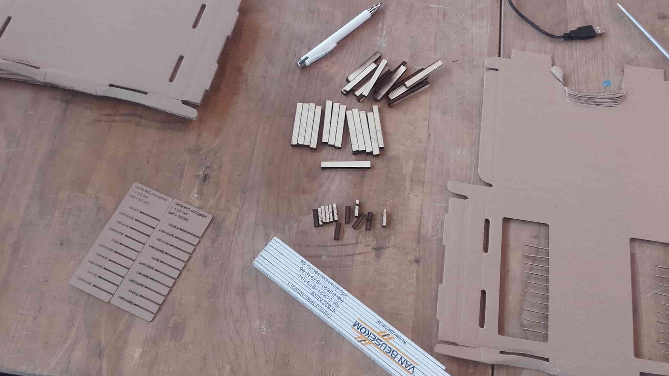
In the end, we made several sets of combs to test the fits for three different wood and cardboard materials. We also wanted to test out some acrylic, but we ran out of time.
My Submission
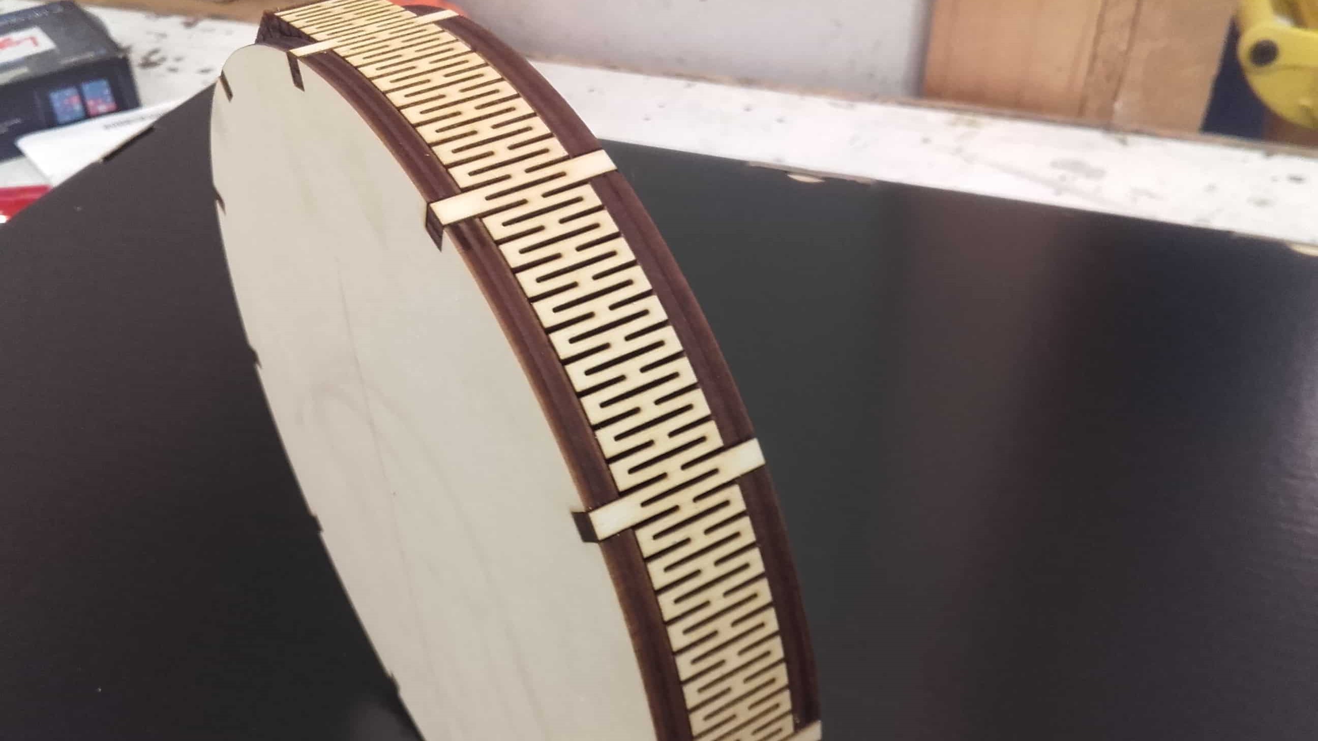
Cutting the Side Pieces
I cut the flexible side pieces first. I would have liked to cut them in one long piece, but the laser cutter wasn't big enough so I cut the part in half and cut it in two separate jobs.
Cutting the Backplate
Then I cut the backplate.
Bad Focus
Unfortunately, I realized too late that the material I used was so badly bowed that for parts of the cut, the material was nearly touching the cutting head. This resulted in a non-constant focal distance for the cut and the cut did not go all the way through in some places.
Re-cutting the Backplate
So I grabbed a new piece of material and weighed it down all around the intended cutting area. It wasn't a perfect solution, but it worked.
Test Fit
The pieces I had cut so far, fit together beautifully.
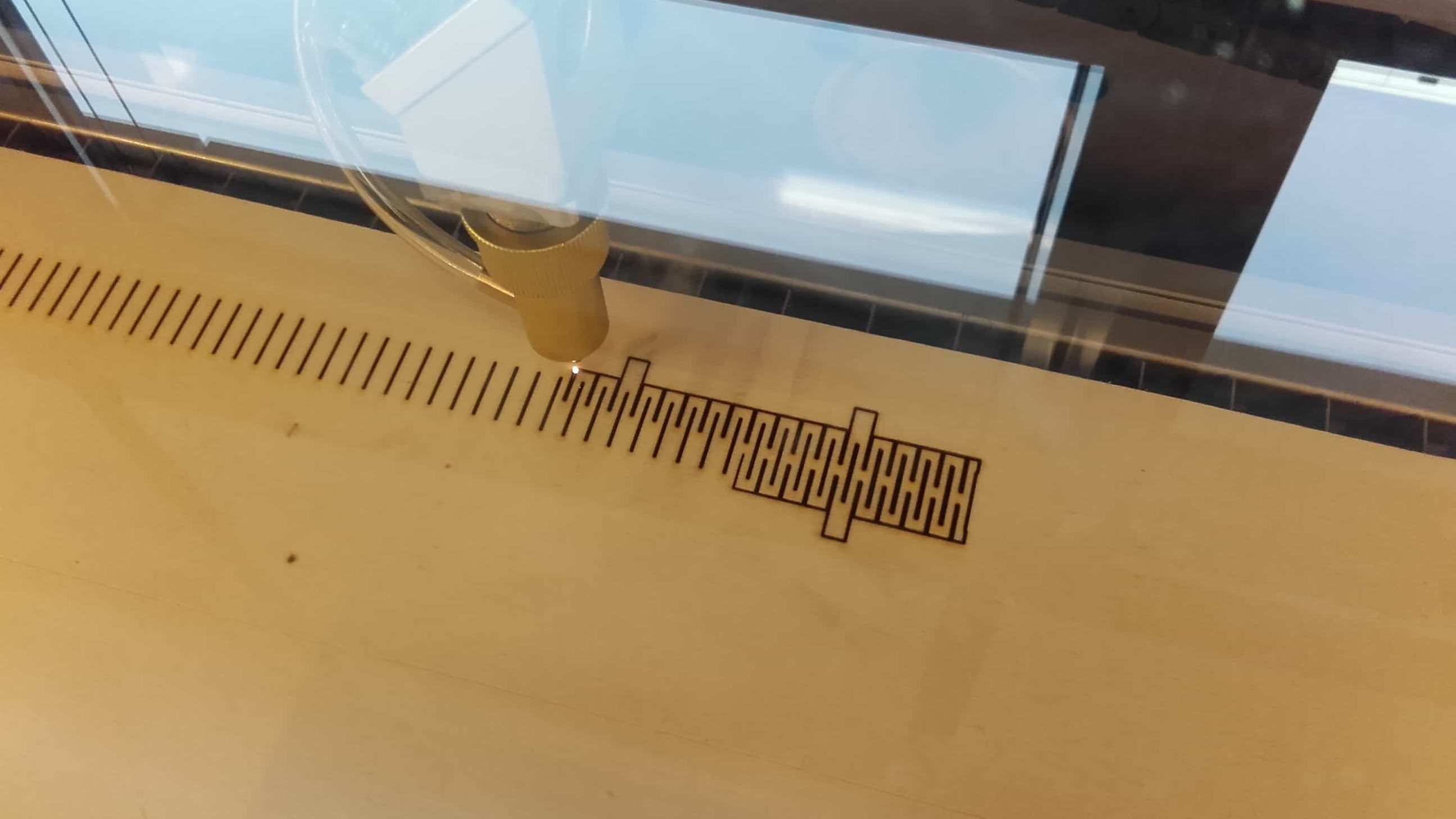
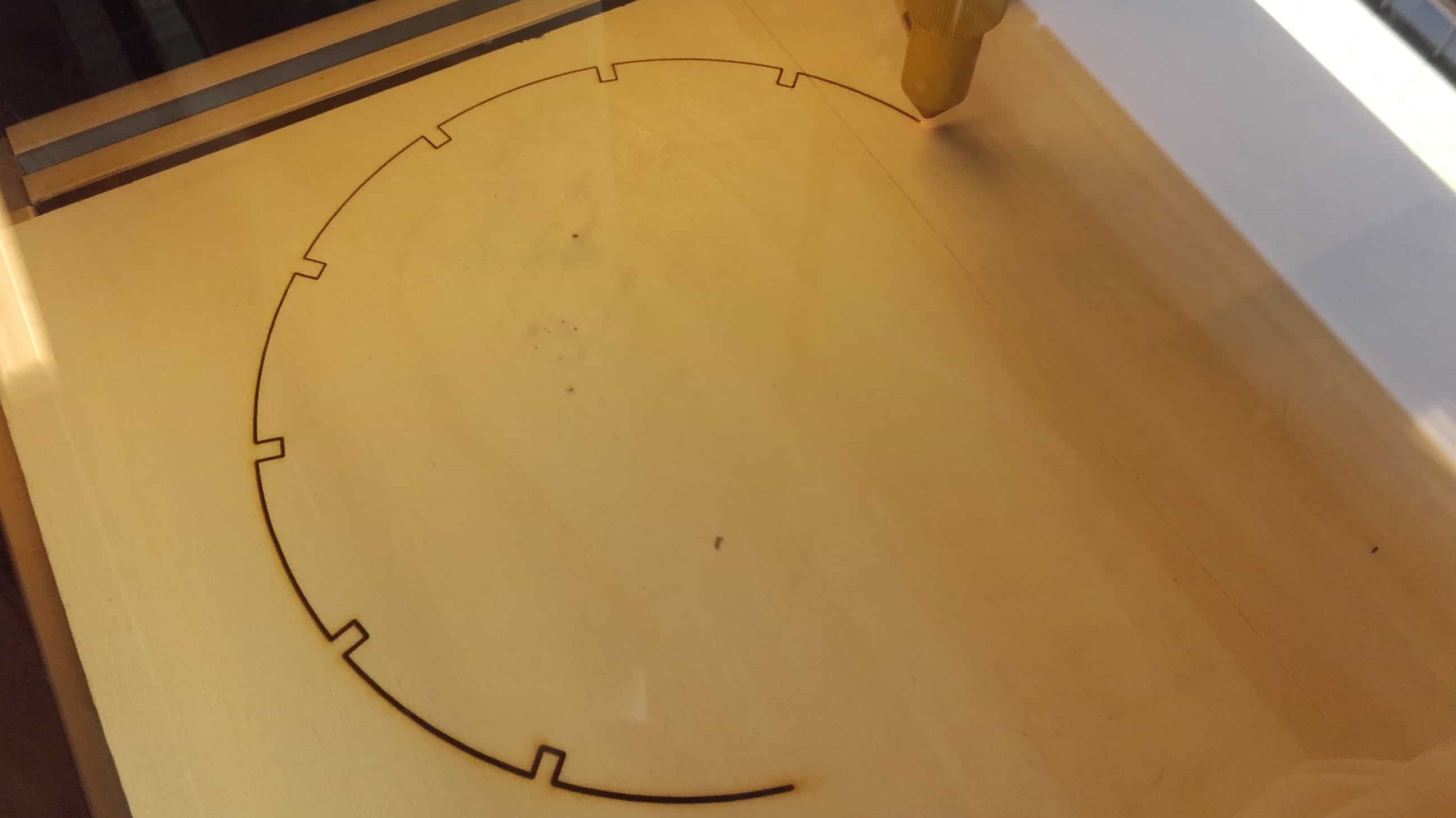
Engraving Test
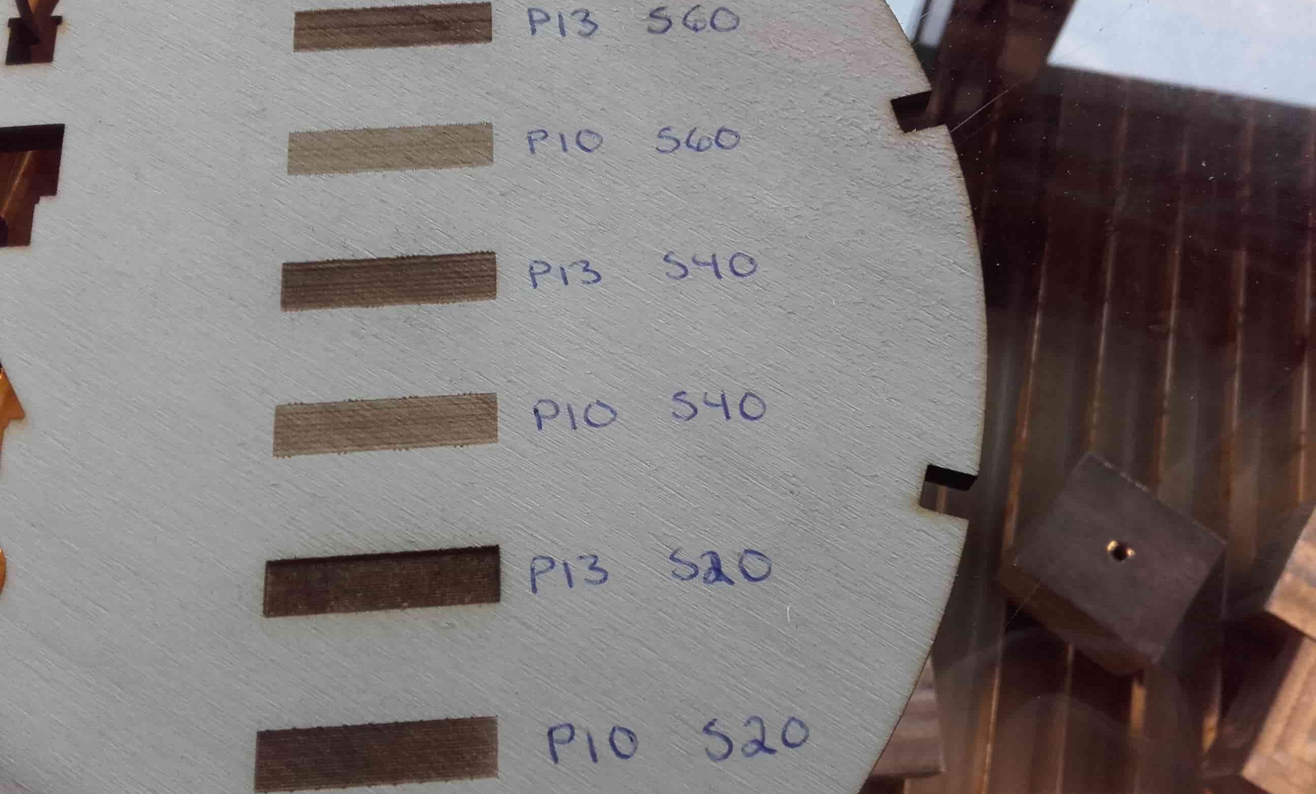
I wanted to try out some 2D engraving for the face of the clock, so I decided to do another small test to get a feel for the parameters since that's not something we had tackled as a group. I tried combinations of two different power settings (10 and 13) and three different cutting speeds (20, 40 and 60).
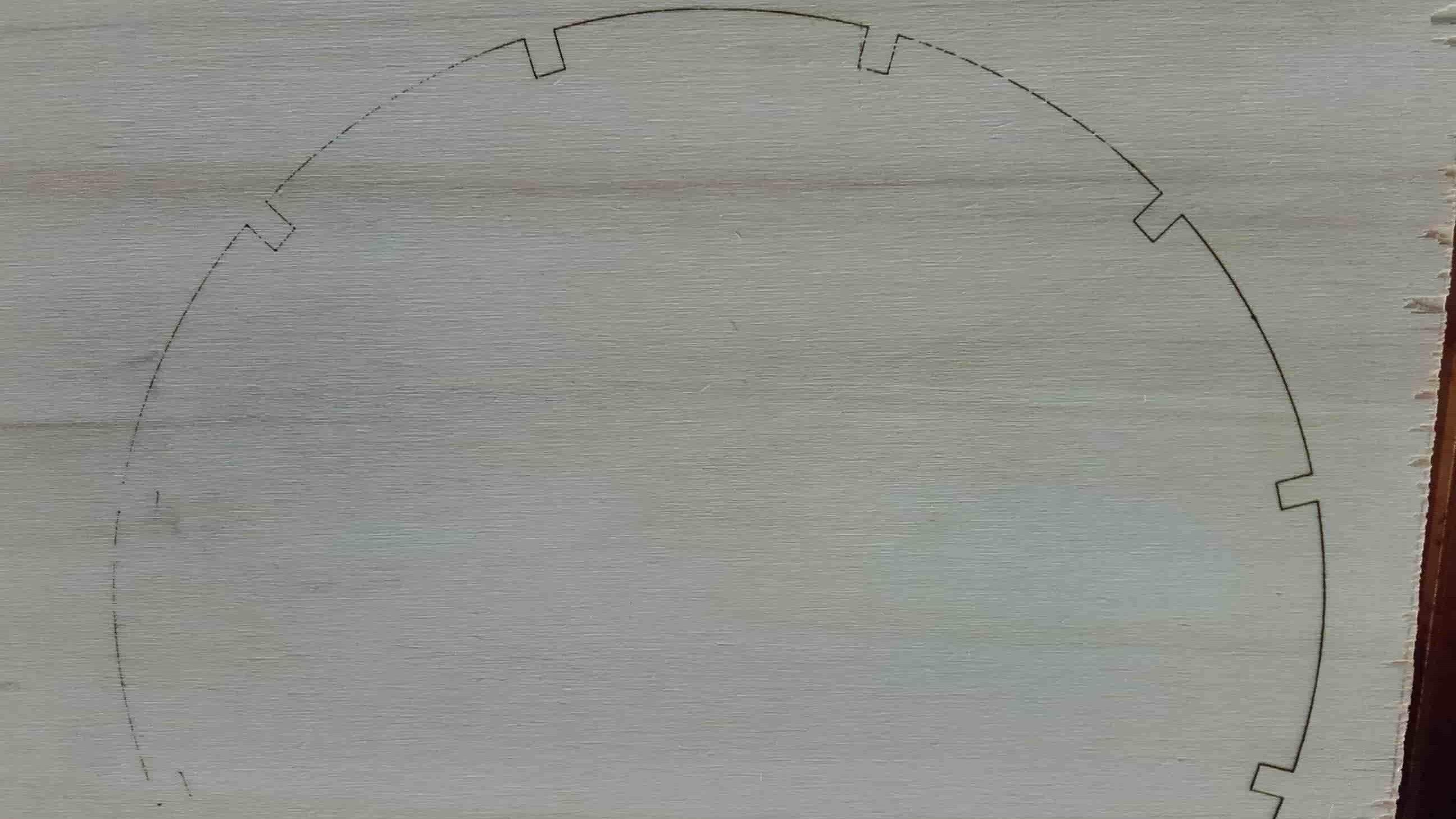
Strange Results
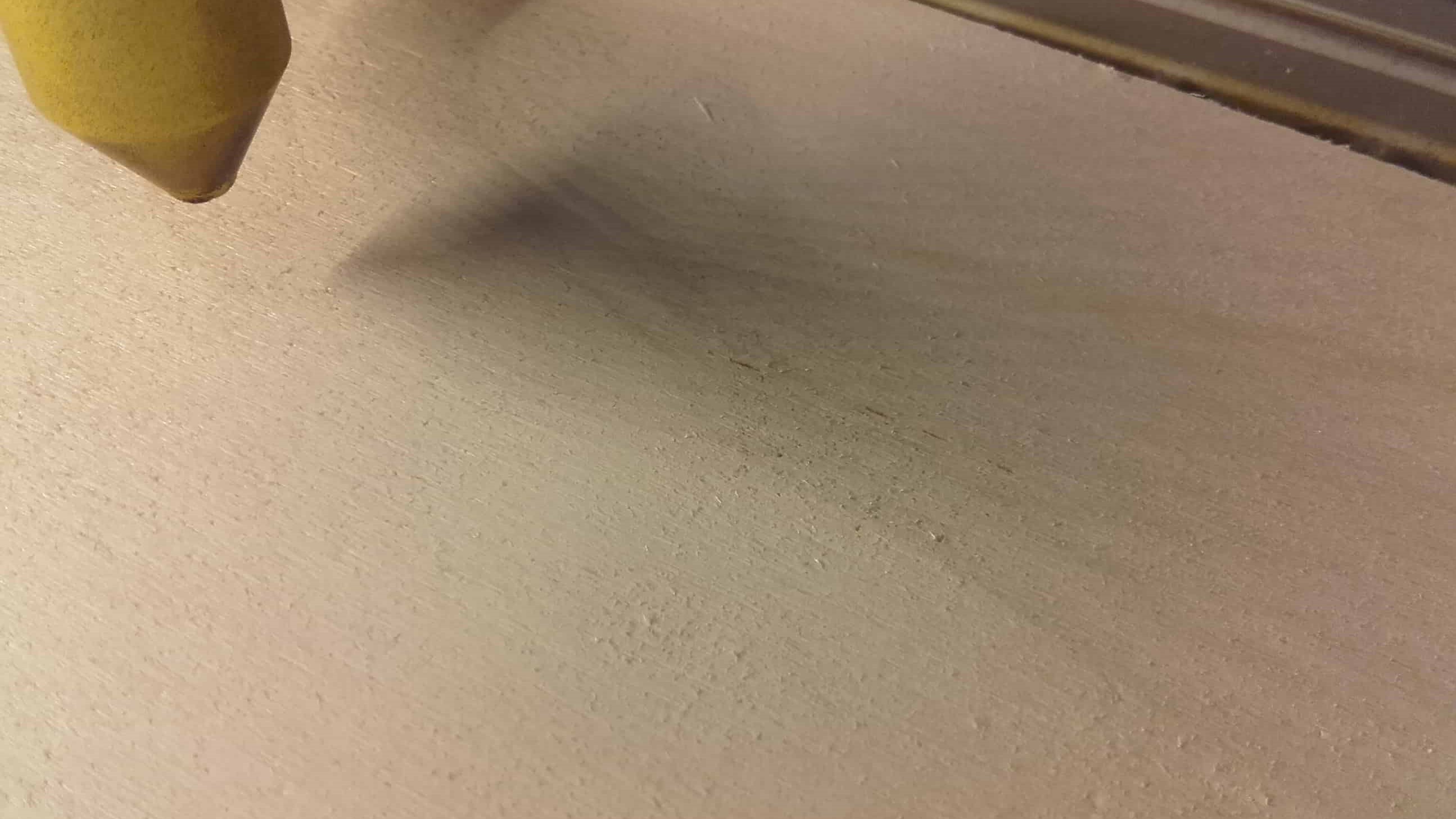
I preferred the p:10,s:20 result so I tried that combination for the numbers on my clockface. Unfortunately, the behavior in my cut was quite different from that in my little test. This pic should show the XII, but it was barely visible even in person.
Try with More Power
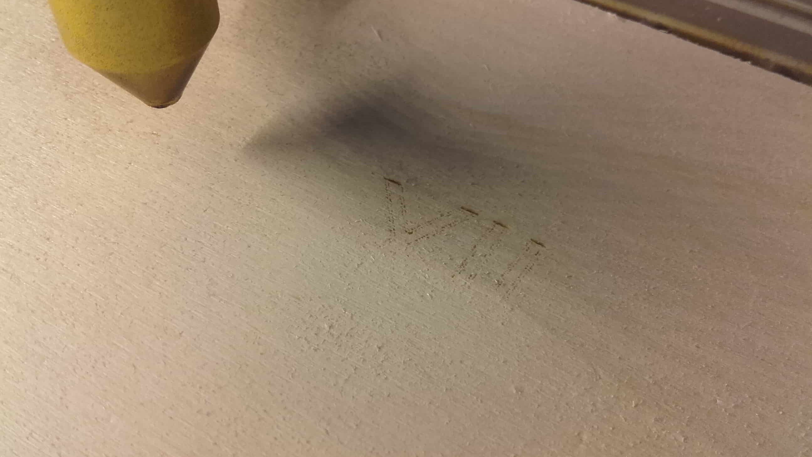
I tried again, this time using power 15 (more than all my tests) and got a similar result. It was at least visible this time, but it definitely wasn't acceptable.
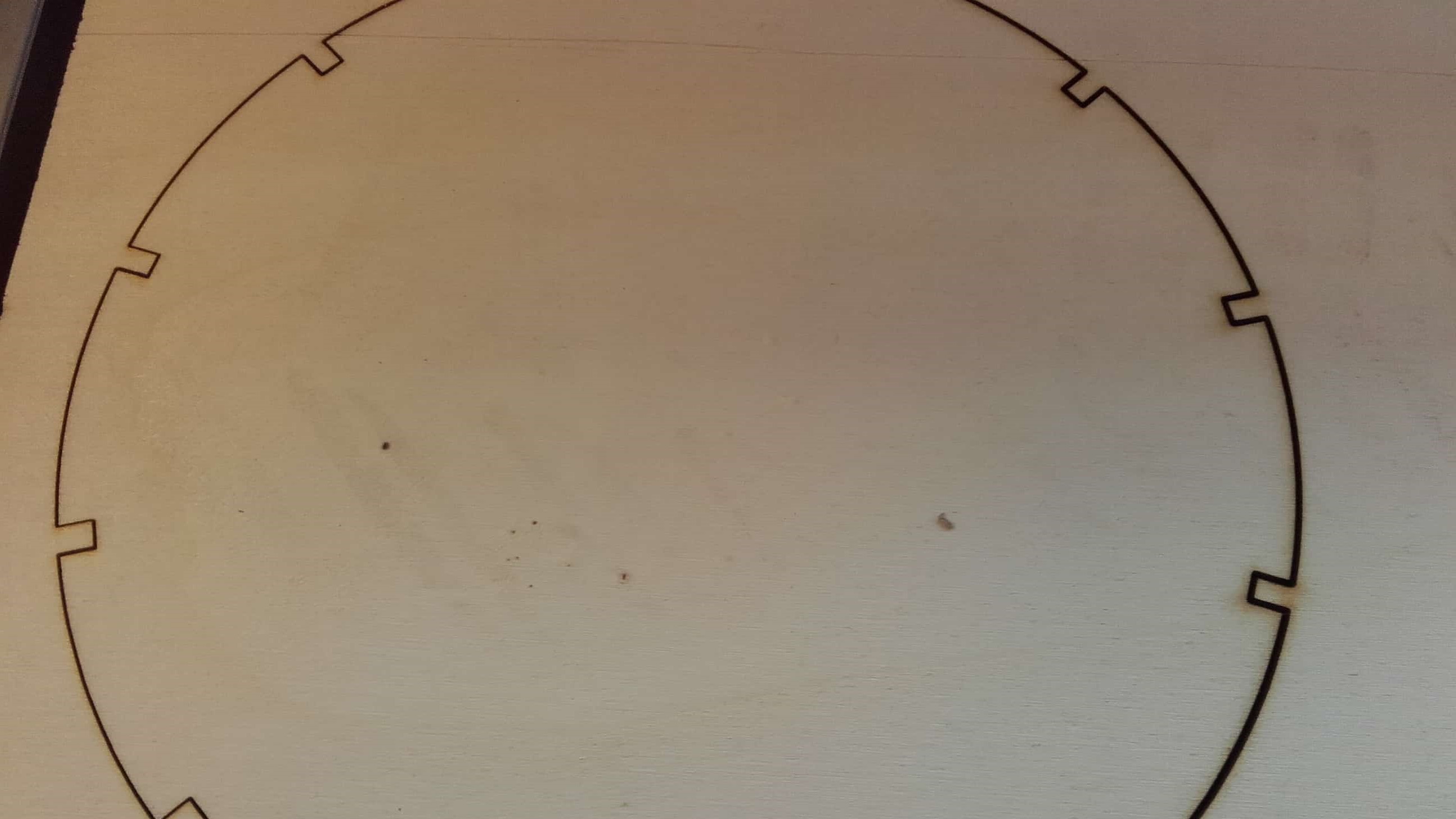
Use Mark Instead
The engraving wasn't working and I had less than an hour remaining before the review session so I just decided to mark the details instead of engraving them. It actually worked out quite nicely.
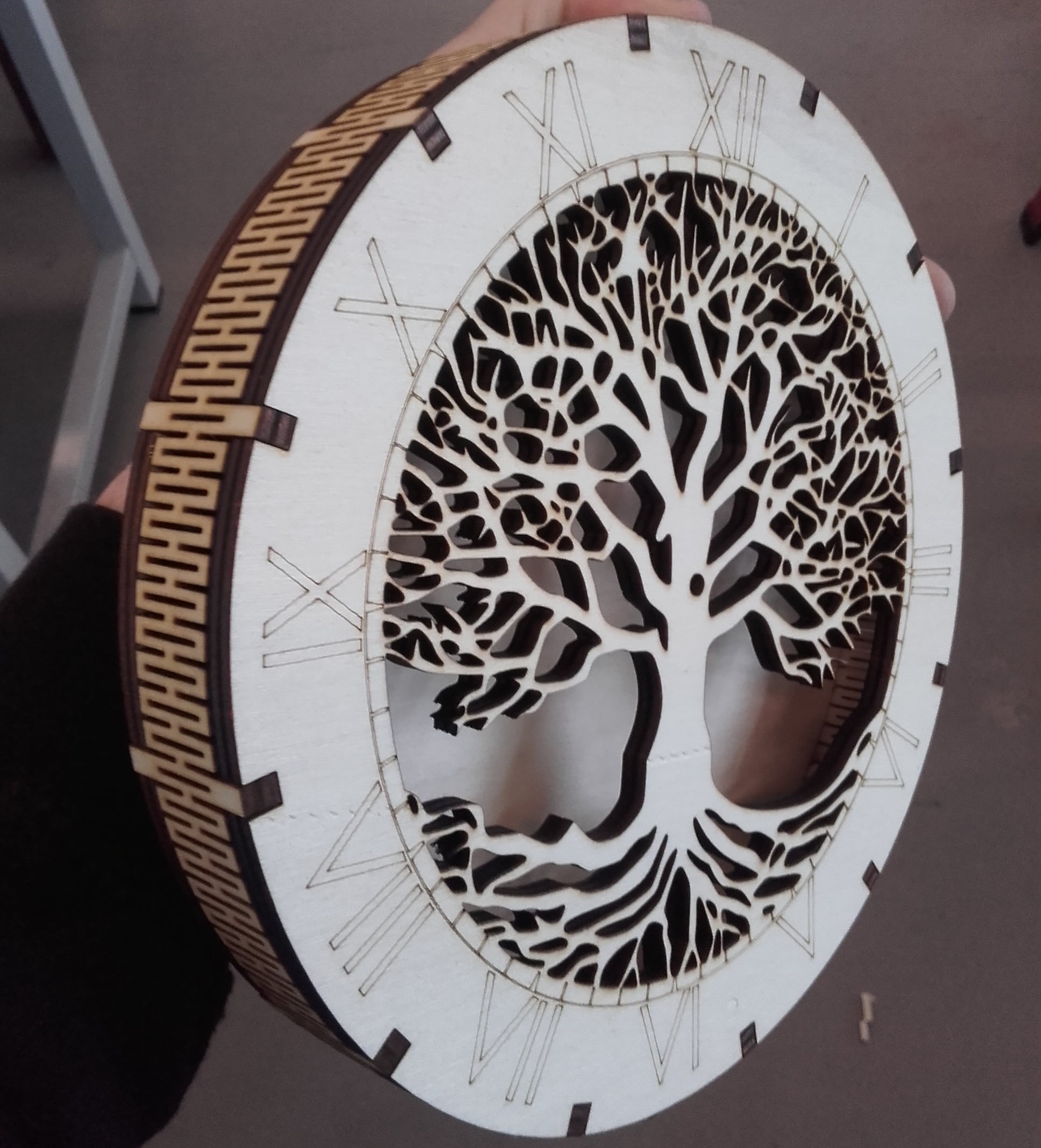
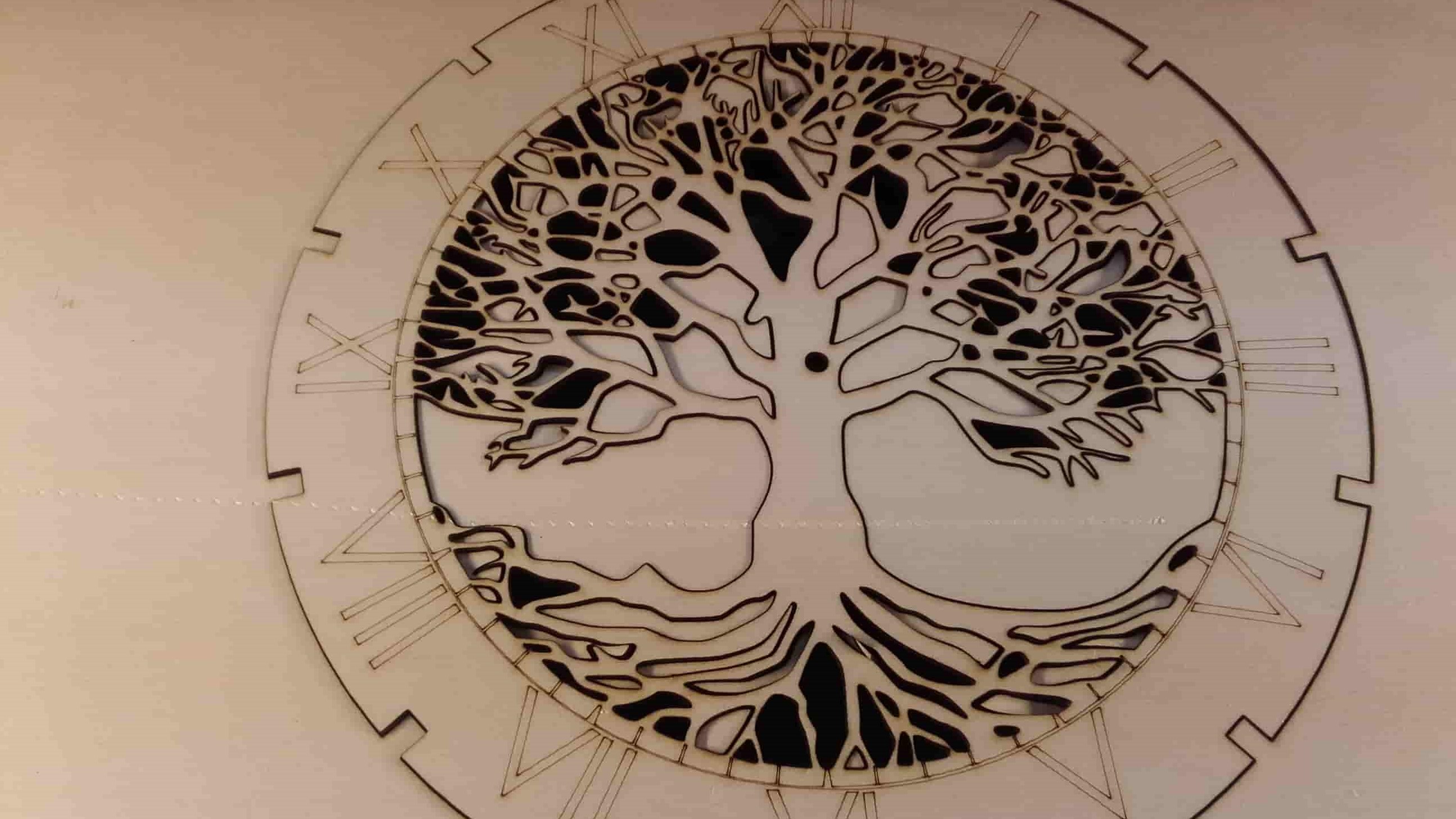
Final Result
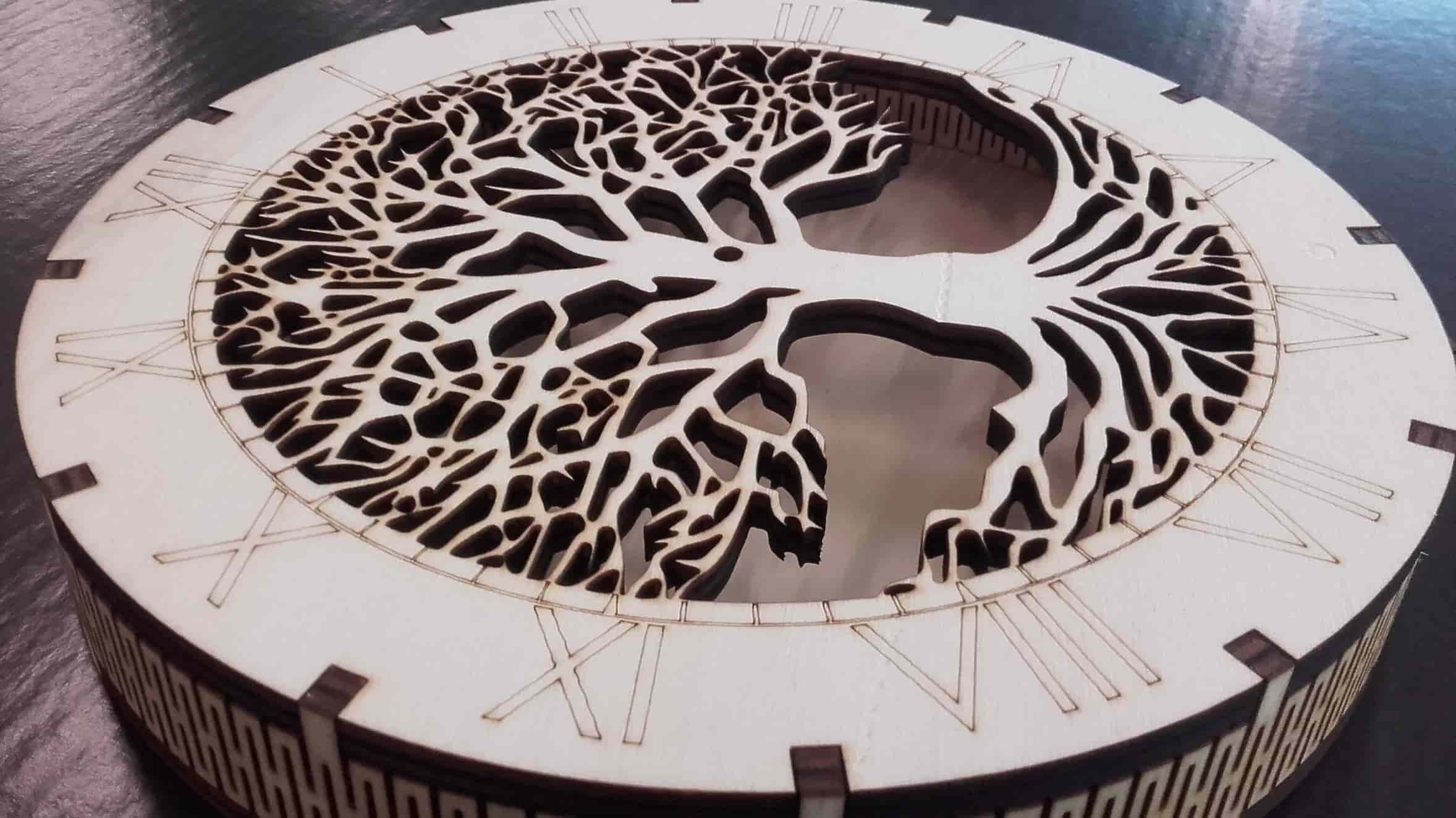
I fitted everything together and was fairly pleased with the results. When I eventually make the final version of this clock, I will have to buy some material with fewer scratches and dents because they are quite noticible.
Redoing the Assignment
Inkscape
And then opened it up in Inkscape.
Ungroup
I used Shift+Ctrl+G to break the group of paths apart and then deleted the parts I didn't want in my cut..
Keep Chaining
...to group all the individual, disconnected paths...
Chained
...into one continuous path. Then I saved the file as an svg and closed Inkscape.
VisiCut
I opened the svg in VisiCut and set it to cut the entire path with a power of 50 and a speed of 2, and then I exported the gcode and closed VisiCut.
UGS
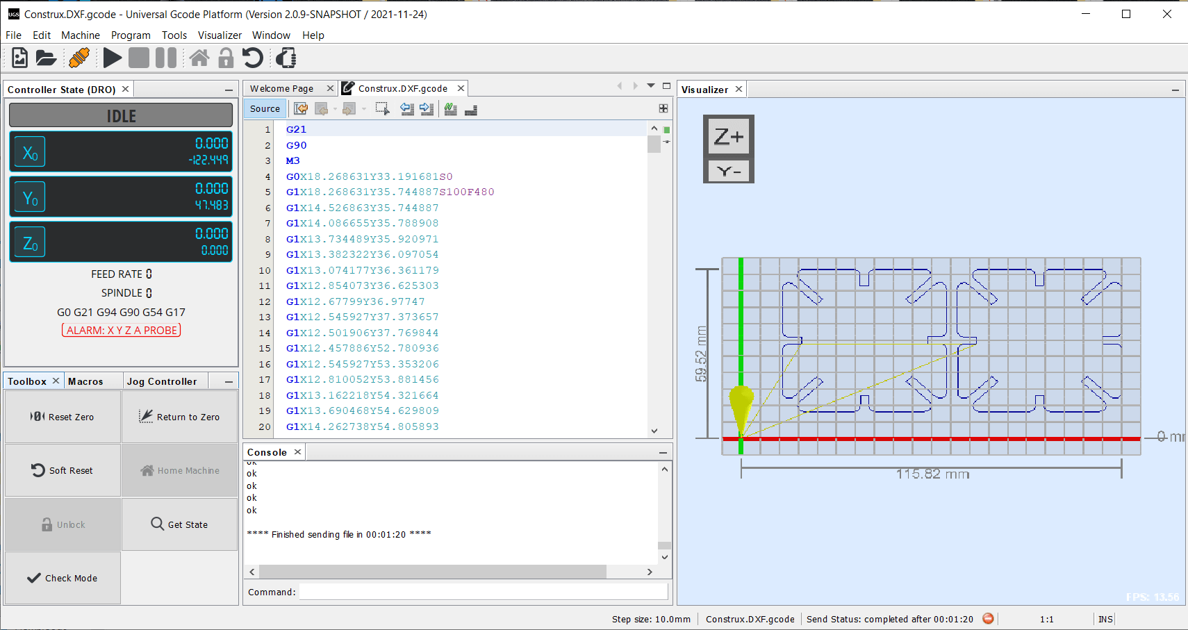
And opened up the new gcode in Universal Gcode Sender. I set the focus of the laser cutter to 7.25 mm (8mm - 1/2 my material thickness), turned on all of the ventilation machines (both for extraction and for air assist), put the hose out the window so I didn't fill up the lab with smoke, and then pressed play...
Cutting
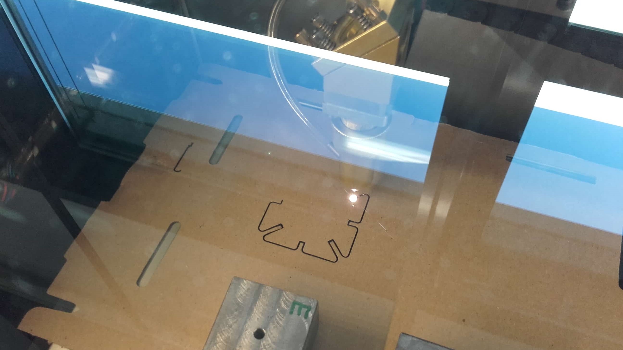
...and watched the fun while the laser cutter started cutting my parts.
Oops
After cutting the first two, I realized I had set the material thickness to 3mm, but my cardboard was only 1.5mm
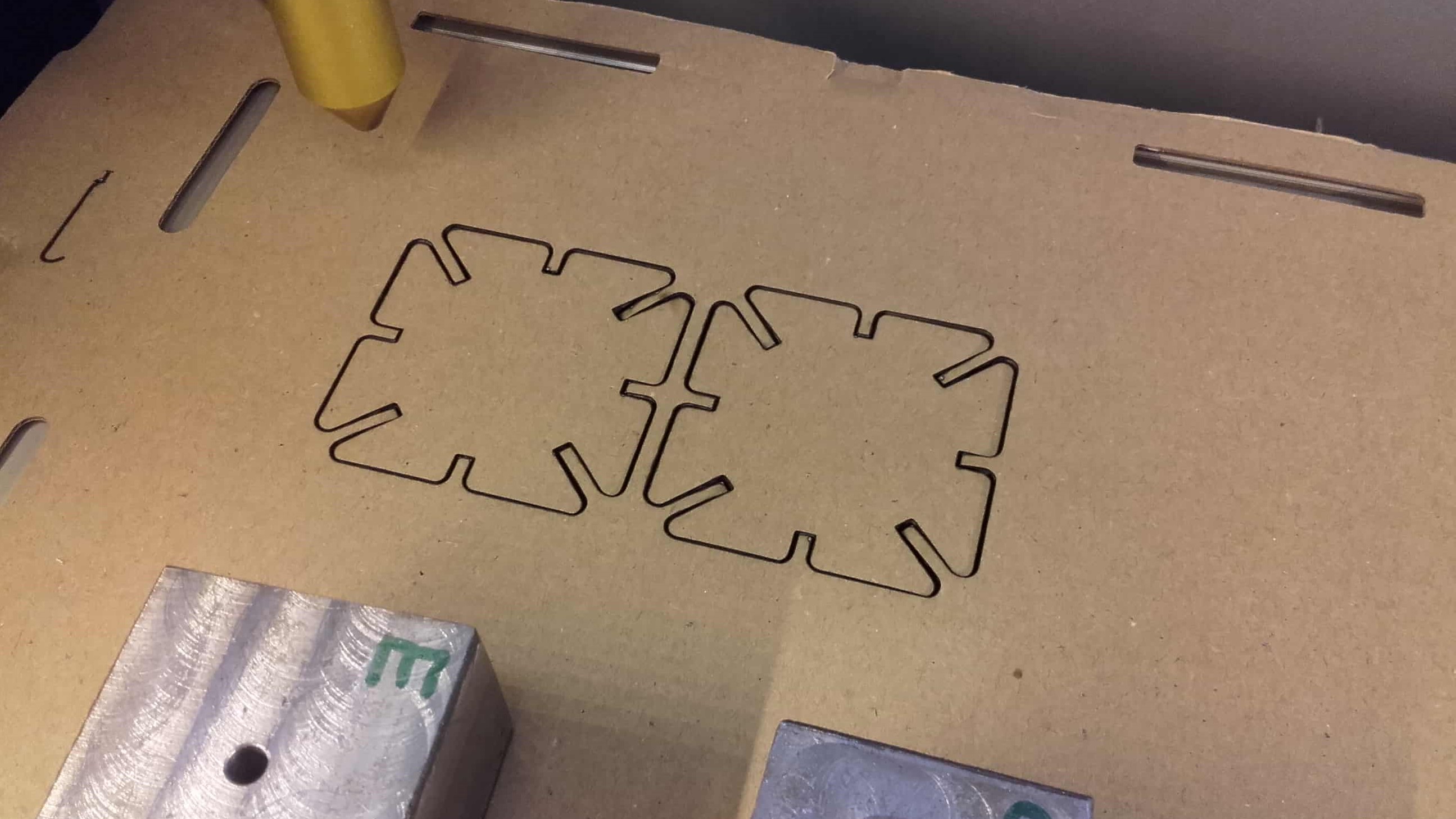
Rinse and Repeat
So I changed that variable in the part file in SolidWorks, and repeated the DXF to svg to gcode process once again.
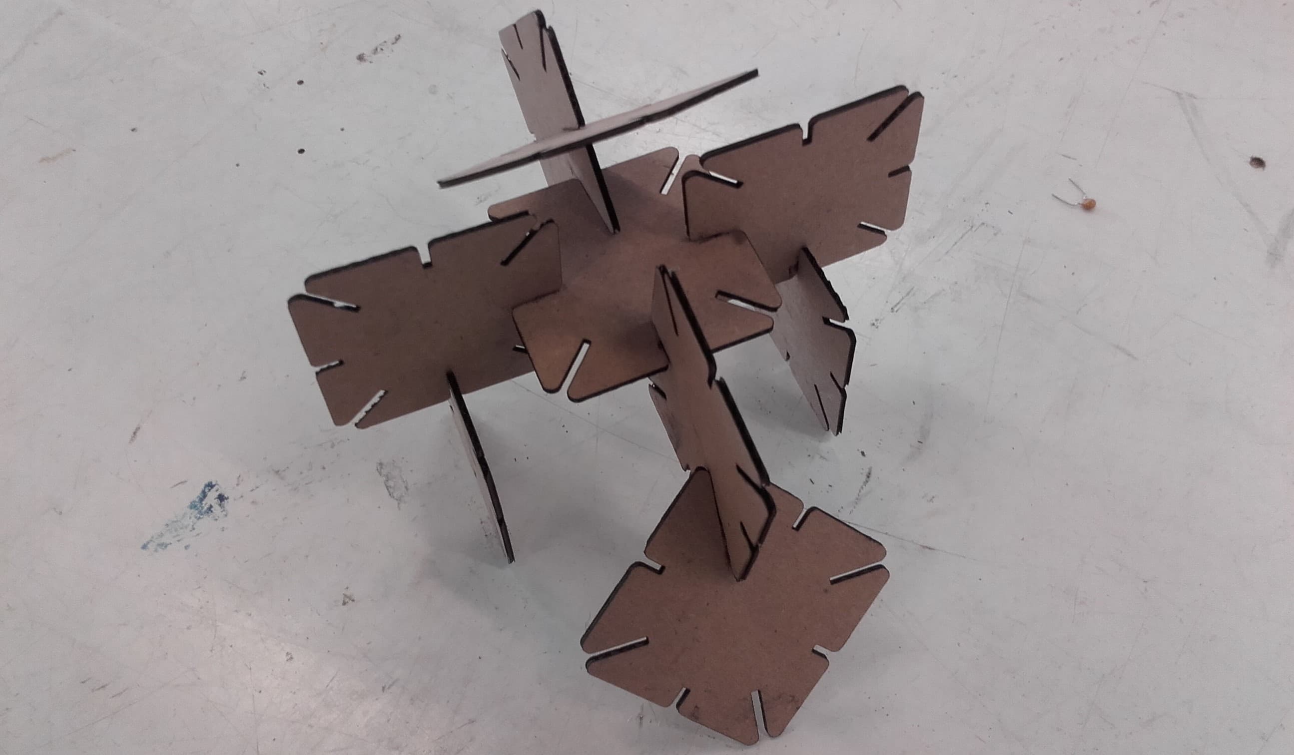
Construx...The Assembly
Finally all cut and fitting together nicely, the Construx project made its final pose for its hero shot.