Mechanical Design and Machine Design
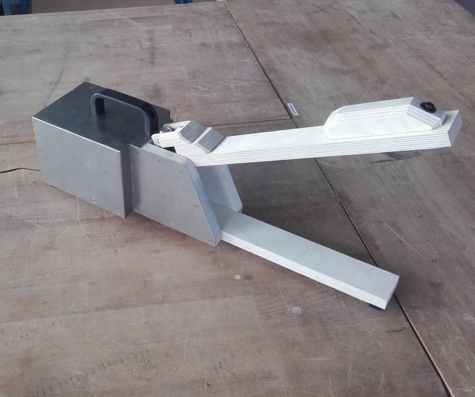
Hero Shot
Click Here for Our Group Assignment
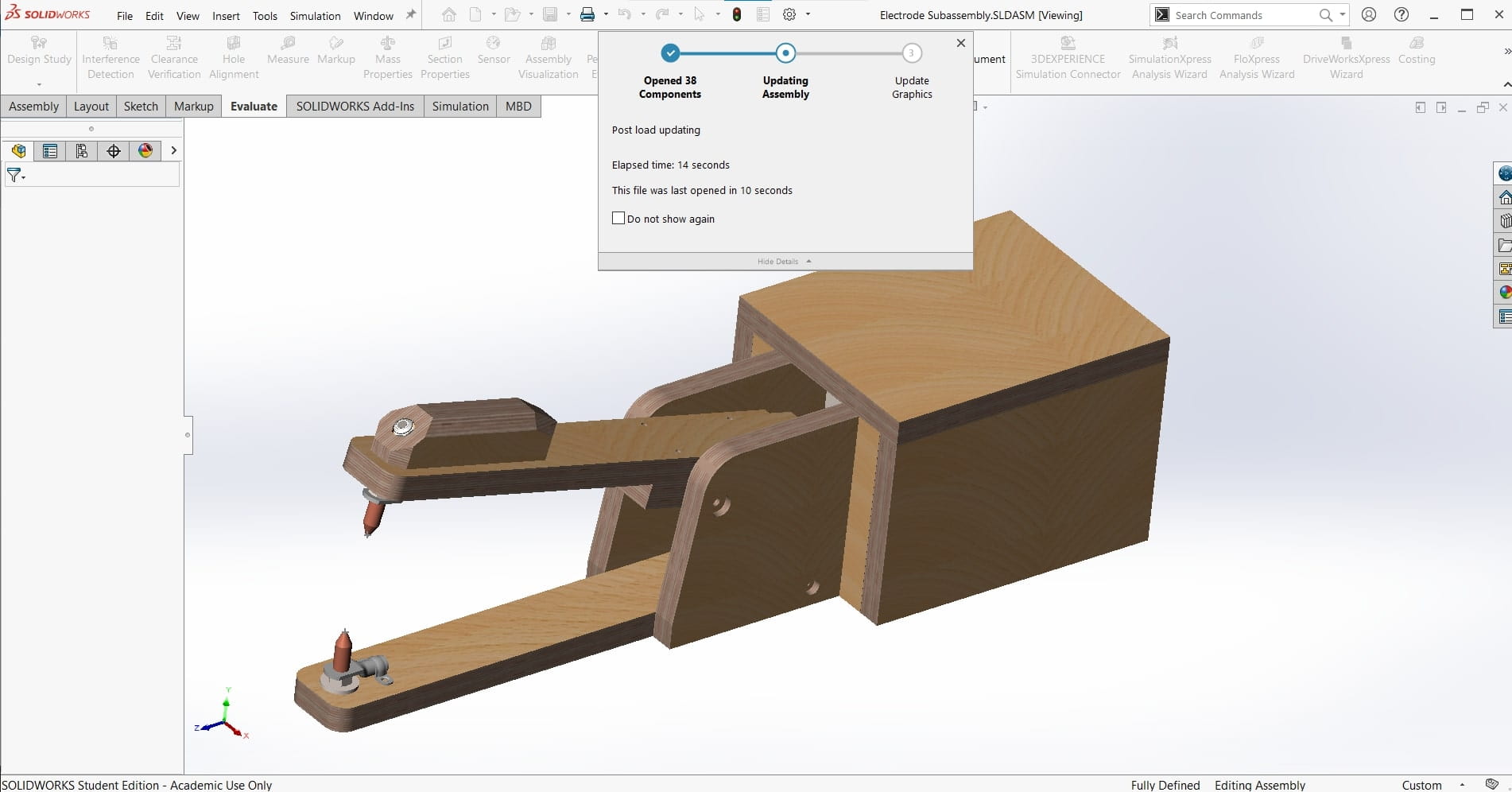
Final Assembly
File Downloads From This Week
- ZIP file with all CAD parts and assembly
- Click Here for Leen's Contribution
- Click Here for Roland's Contribution
CAD Assembly
Initial Reaction
I am really excited for this one! Machine design is my passion and it's quite literally why I am taking this course. As usual, Neil gave us a brief introduction to the possibilities as well as some great examples of past submissions. There are so many badasses that are alumni of FabAcademy! It's very inspirational. For this assignment, we only have a group project; we are to design and build a machine that is functional, actuated, automated and applicable. Roland is still recovering from Covid19, so I guess Leen and I will be getting started tomorrow, and he can help once he is feeling better. I can't wait! I want to start designing right away.
After Local Workshop
The local workshop was very short this week. We met for about a half hour to discuss our ideas for the machine we want to design and build. The Kleve team is going to build a spot welder for our lab. We still need to work out the details of meeting the requirements of the assignment, but the machine will be a nice addition to the lab if we are successful.
Detailed CAD Design
The Plan
A few weeks ago, my dad sent me a video of a DIY spot welder made from an old microwave transformer. I thought it was a cool idea and we could use one for the lab, so I sent it to Leen and Roland since we were on the market for a machine to build this week. They liked it too so we agreed to make it. We had to make a few adjustments to make it more suitable for our purposes and to fulfill the requirements of the assignment. Actuation lends itself easily to this machine since we wanted to add a foot pedal to the original design anyway, but We had difficulty coming up with a way to automate it without making it exponentially more complicated or reducing its overall functionality. In the end we decided to add a wireless bubble machine to it. This will serve as a warning sign that the welder is in use as well as a distraction to look at instead of the arc (spot welders don't make arcs that are actually dangerous, so this is more about functionality). And of course, the intensity and duration of the bubbles can be programmed and performed automatically.
This Document
Since corona is disrupting the normal flow of our group right now, we decided to divide our efforts for the design stages. I will handle the mechanical design, Leen will take care of the electronics, and Roland will do the programming. Since they need the mechanical design to be largely done in order to get started, I decided to get busy right away.
There are over 20 parts to this machine so I have chosen not to document every step of the CAD design of every part. I think that would just be tedious for us both. So, for the purposes of this process documentation, I decided to only write about the design decisions and the overall process of designing as well as the finished detailed CAD design. For the sake of brevity, I will only include the highlights of the CAD work here. More images and information are available upon request if the reviewers feel that what I have included is insufficient.
Info from Screenshots
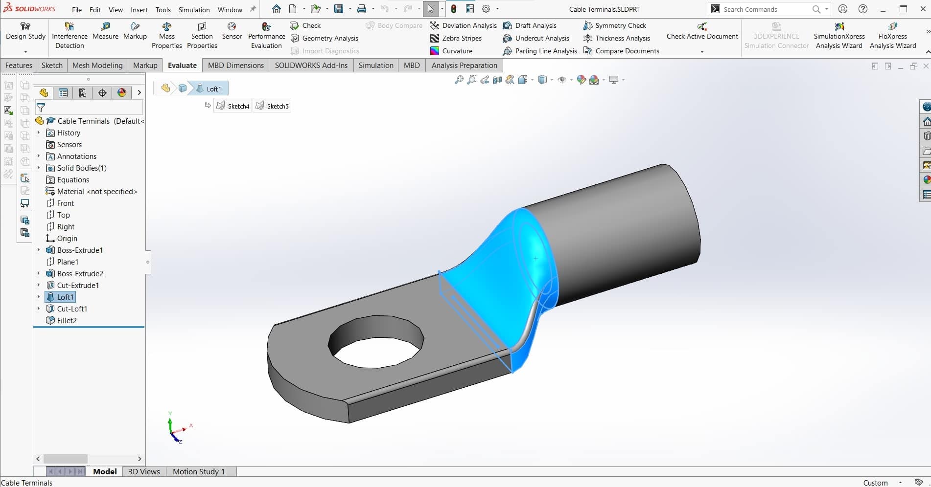
I began by re-watching the video. There were a couple useful screen-grabs that allowed me to figure out what hardware the maker was using, and from there, I was able to speculate about the overall dimensions of the machine and the components that were being used. My first CAD part was the cable terminal and everything else was built based off of that.
Copper Electrodes
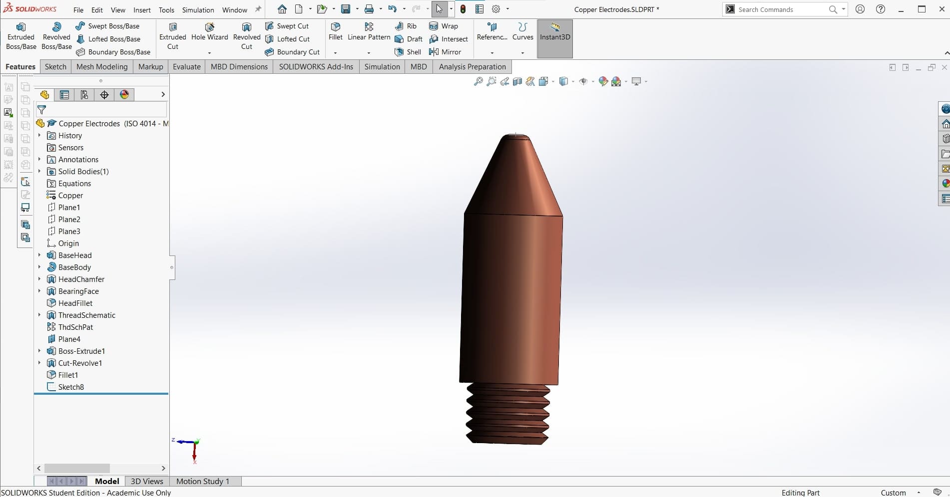
Next I made the copper electrodes that would be the welding tips...
Cable Clamps
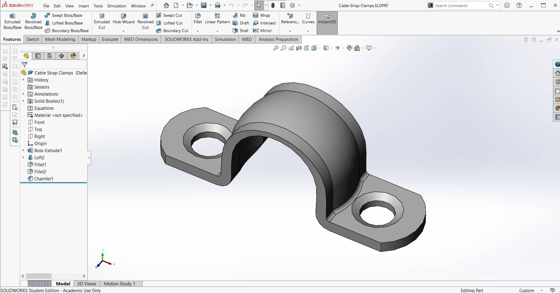
...and the cable clamps. These are are simple parts so there is no deed for too much extra detail.
Bottom Jaw
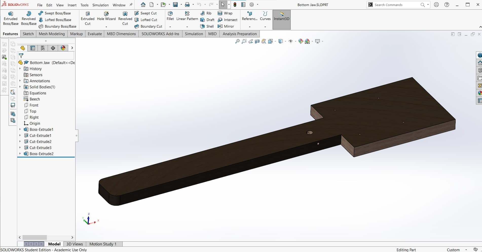
Once I had the welding ends of the machine assembled with the necessary hardware and mated to allow the desired degree of freedom, then I was able to make the lower jaw part that would serve as the base of the machine onto which everything else would be positioned.
Tension Spring
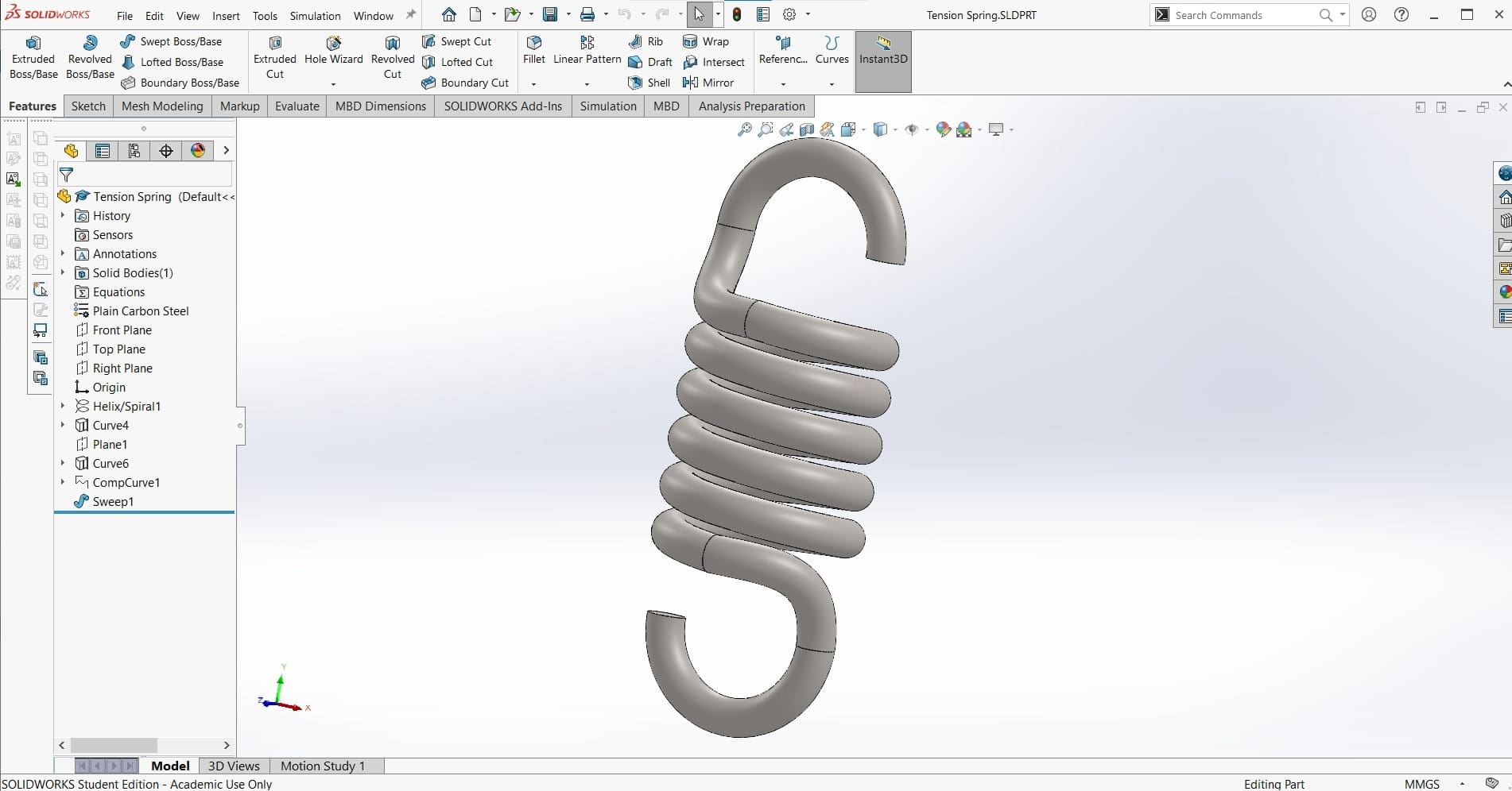
Next, it was time to select the tension spring. Using the size and force parameters I had already worked out, I used this spring calculator to determine the dimensions of the spring we would need. Then I stole a model from GrabCAD and adjusted it to fit the dimensions of our spring.
Eyebolts
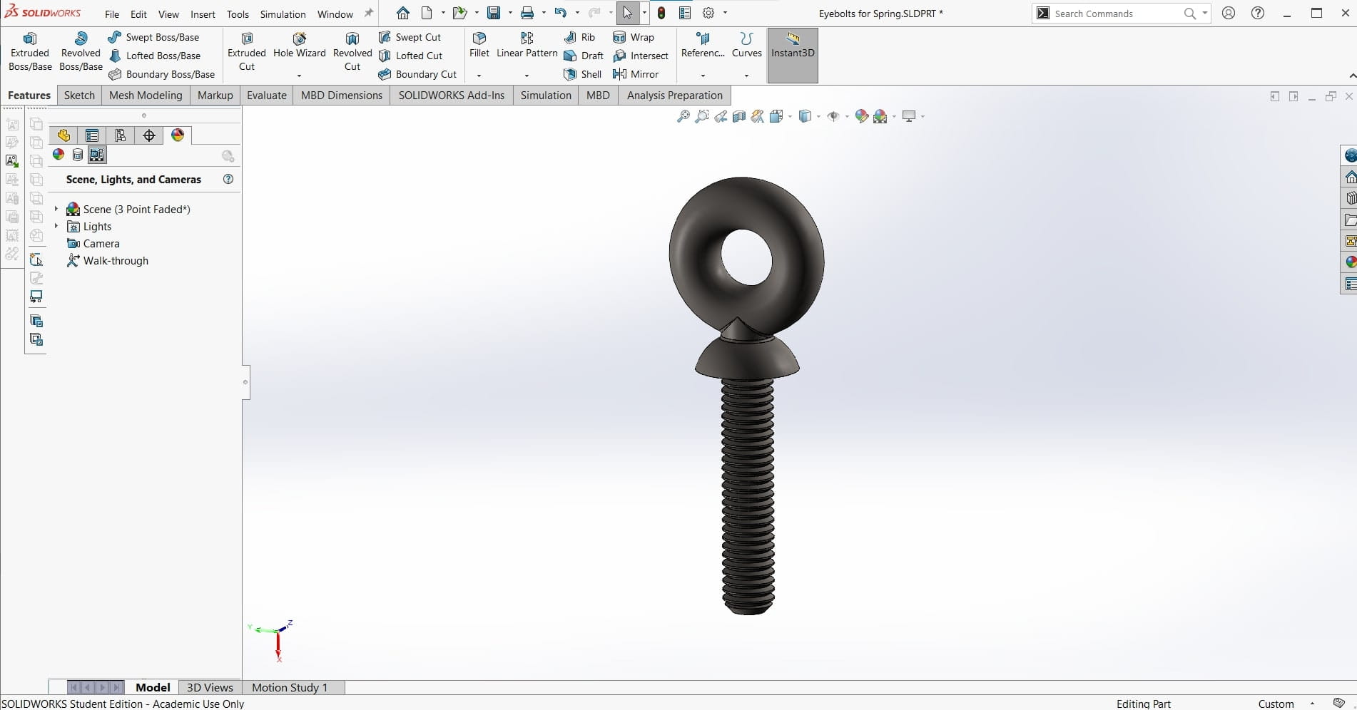
For the eyehole bolts, I couldn't find any models for smaller configurations, so I just decided to make this part myself as well. I started with an M5 bolt, and then extruded the shoulder and eyehole using the Revolve Extrude feature.
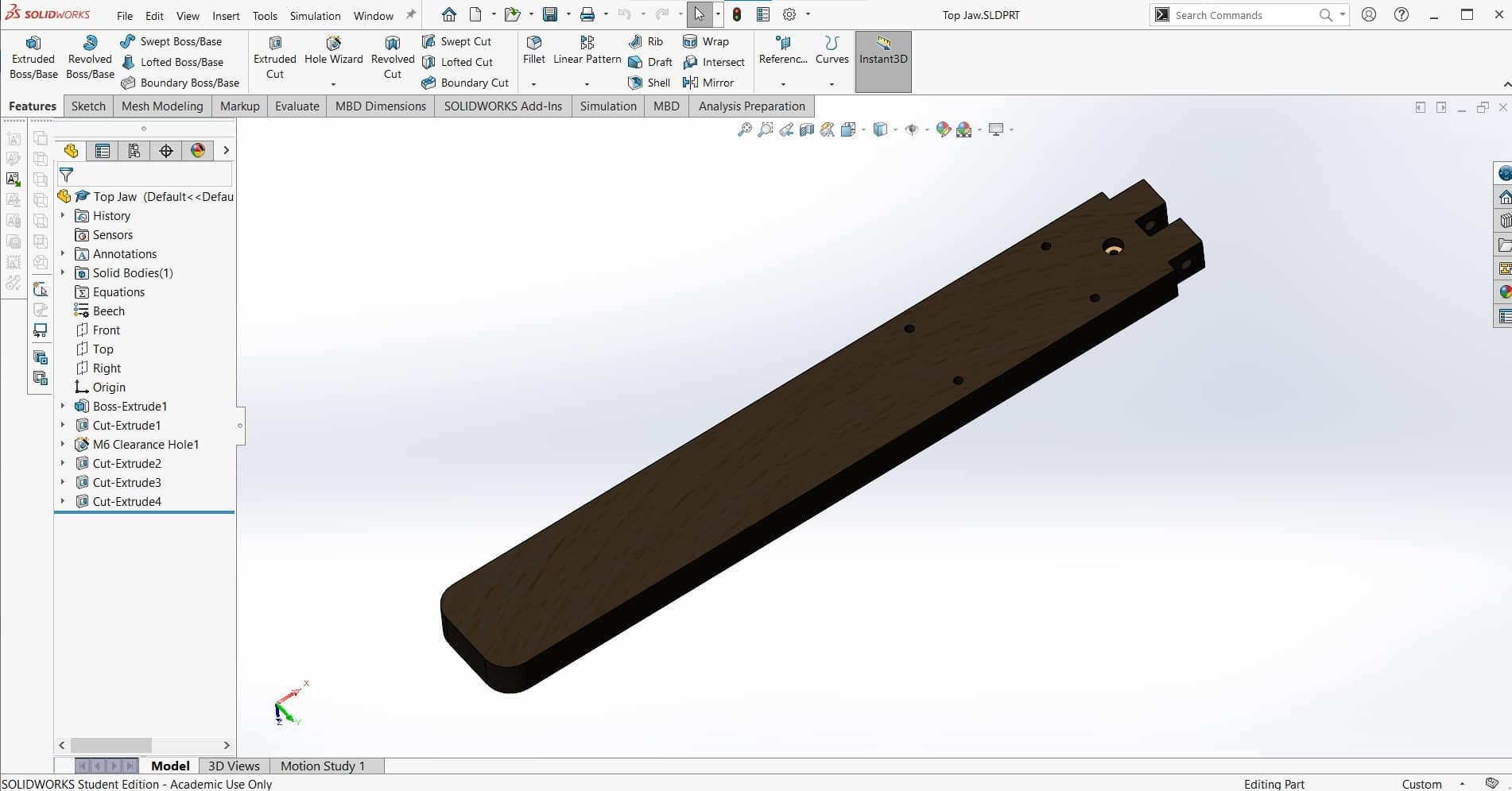
Top Jaw
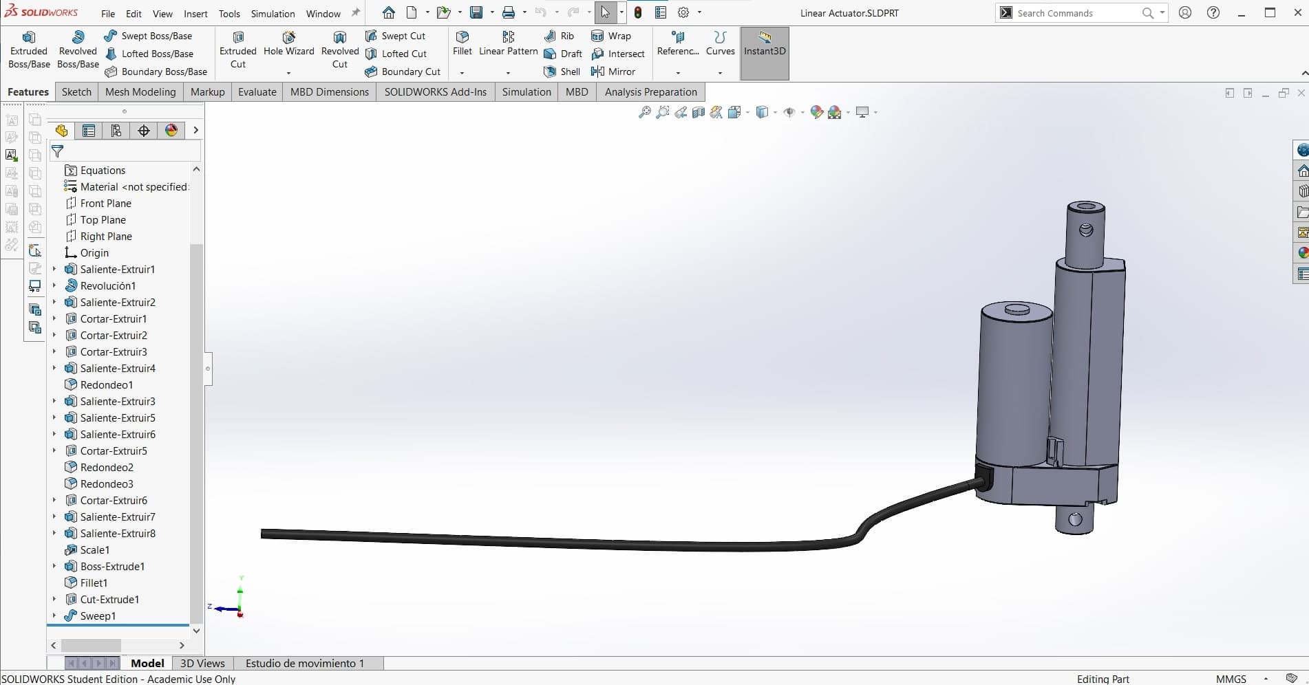
Next I added the linear actuator. Once again, I looked at my force loads and the available space to select the necessary servo. I found a model for one of the configurations in the series that I wanted, and then scaled it to the correct dimensions using the Scale tool.
Linear Actuator
Once I had all of the components for the welding arms attached to the bottom jaw, it was time to create the top jaw. Since everything was already properly lined up, this part was easy to make. I removed the notch from the back to fit the linear actuator.
Microwave Transformer
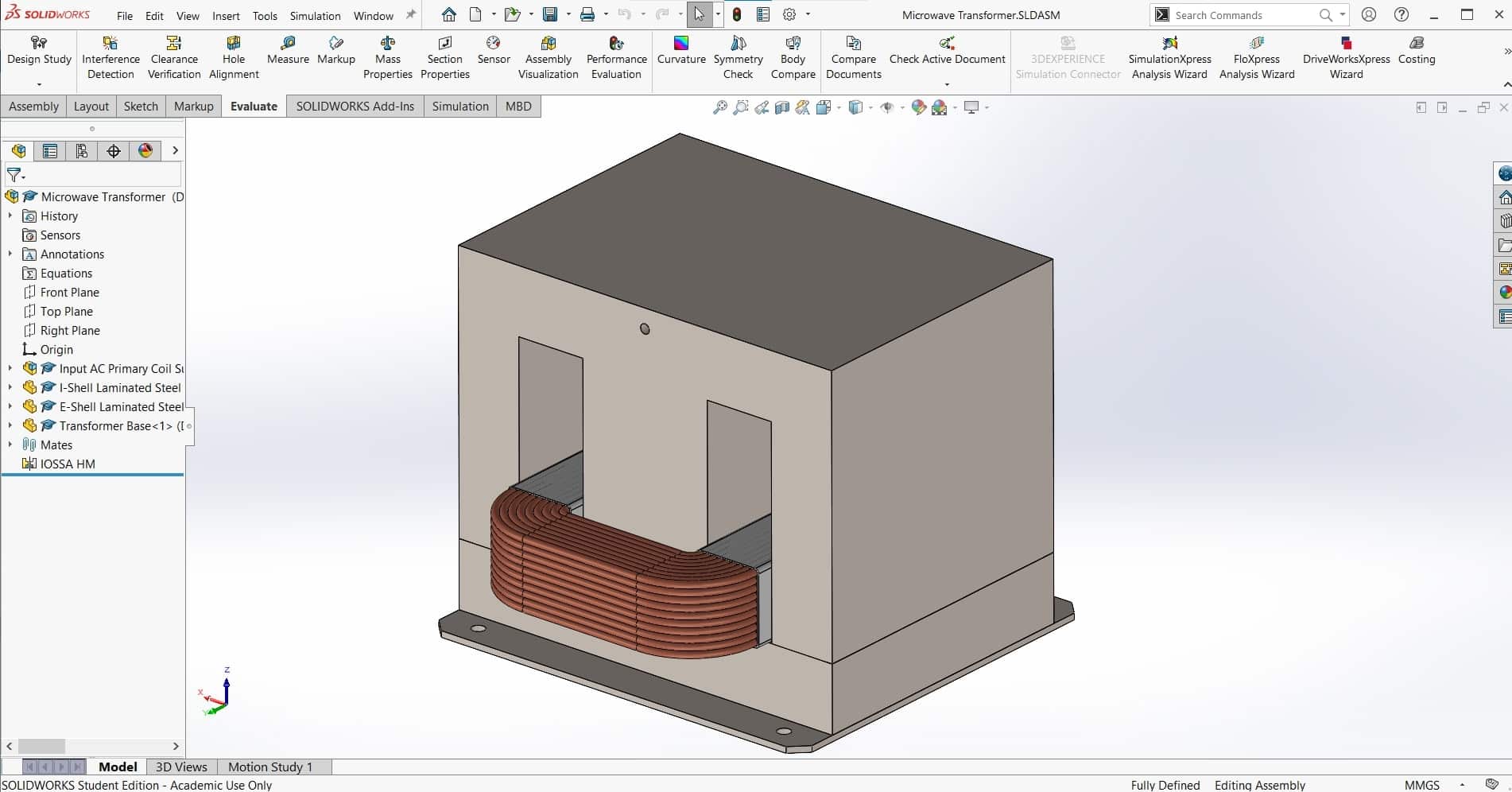 We took the transformer out of the old microwave and looked up the datasheet. Then I found a model once again to get me started. The transformer I downloaded was too detailed for my purposes so I replaced the 152 0.5mm layers of the steel core with solid parts. I also removed the top coil (the coil with the most windings), and then added the subassembly to the assembly.
Fan
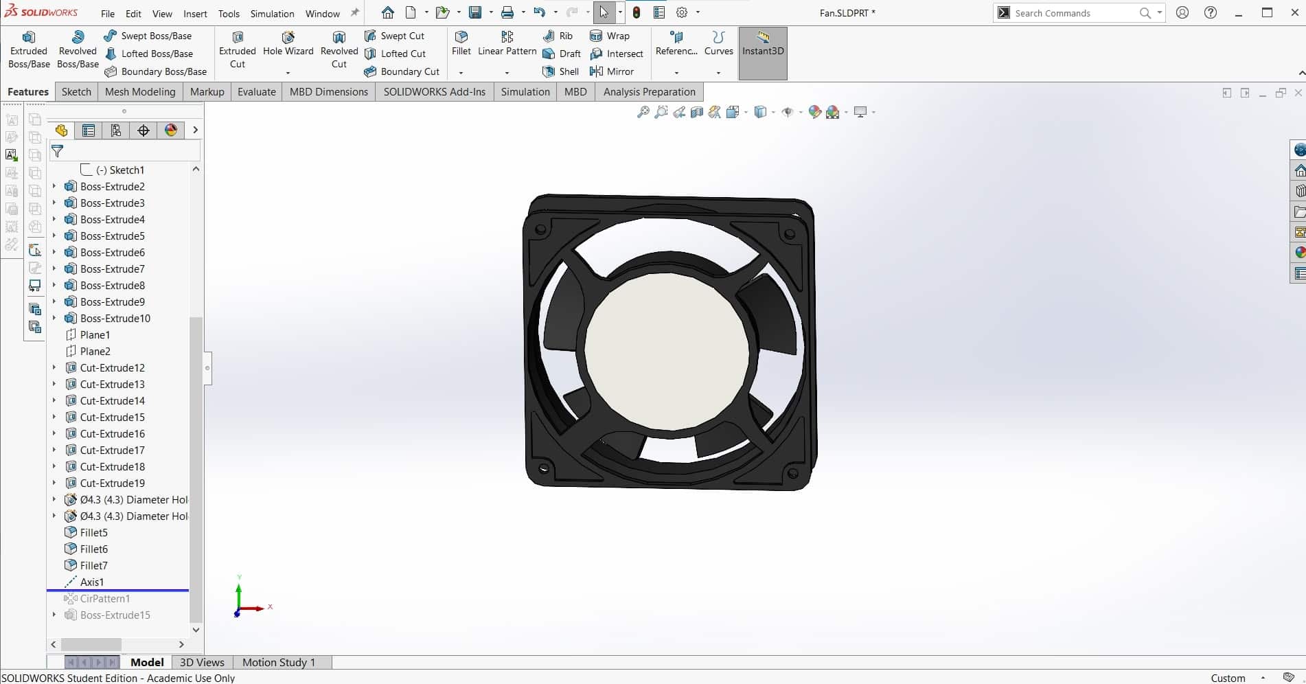
I followed a similar process for the cooling fan. I found a model for a computer box-fan that was the right size, but it was overly complex for my purposes so I removed some features to simplify it. Also strangely, the model was missing one of the five fan blades to I used a Circular Pattern to add it in.
Fulcrum Panels
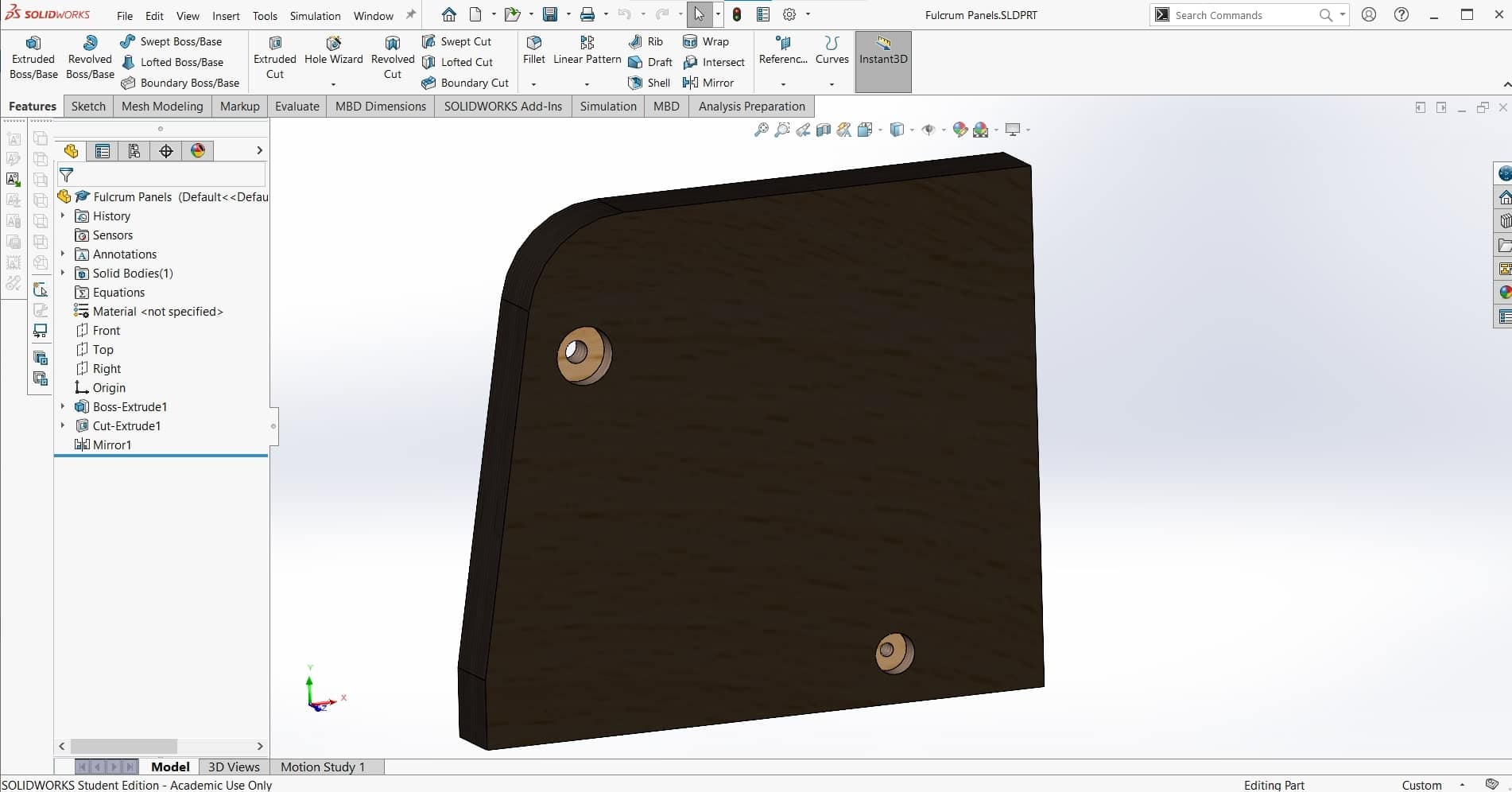
Once I had all the major components in the assembly, I could focus on the structure and housing that would hold it all together. I made the side pieces to hold the pin joint first. Adding the oblique side with the large filet will be more difficult to manufacture, but I am hoping it will be a good trade for a bit more working room between the welding arms.
Handle
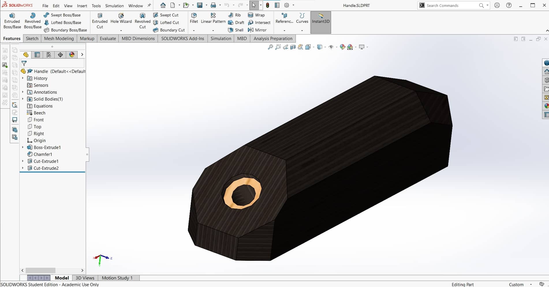
I didn't like the way the upper jaw was made in the video; it doesn't look very comfortable to use. So I decided to add a handle to the top of it that will also house the activation button.
Pushbutton
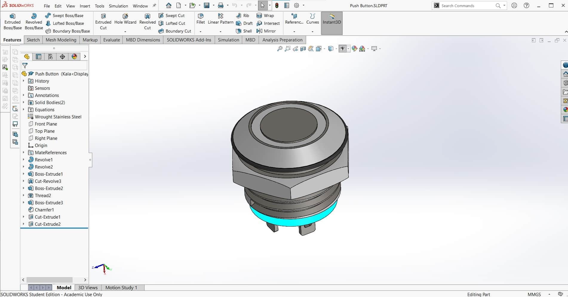
I also found a pushbutton on GrabCAD ton insert into the handle and activate the current.
Ugly Wooden Housing
Finally the function of the machine was complete, so it was time to create the housing. I was initially thinking about a plywood housing made from the same material as the welding arms, but it make the machine look clunky and unappealing to me.
Sheet Metal Housing
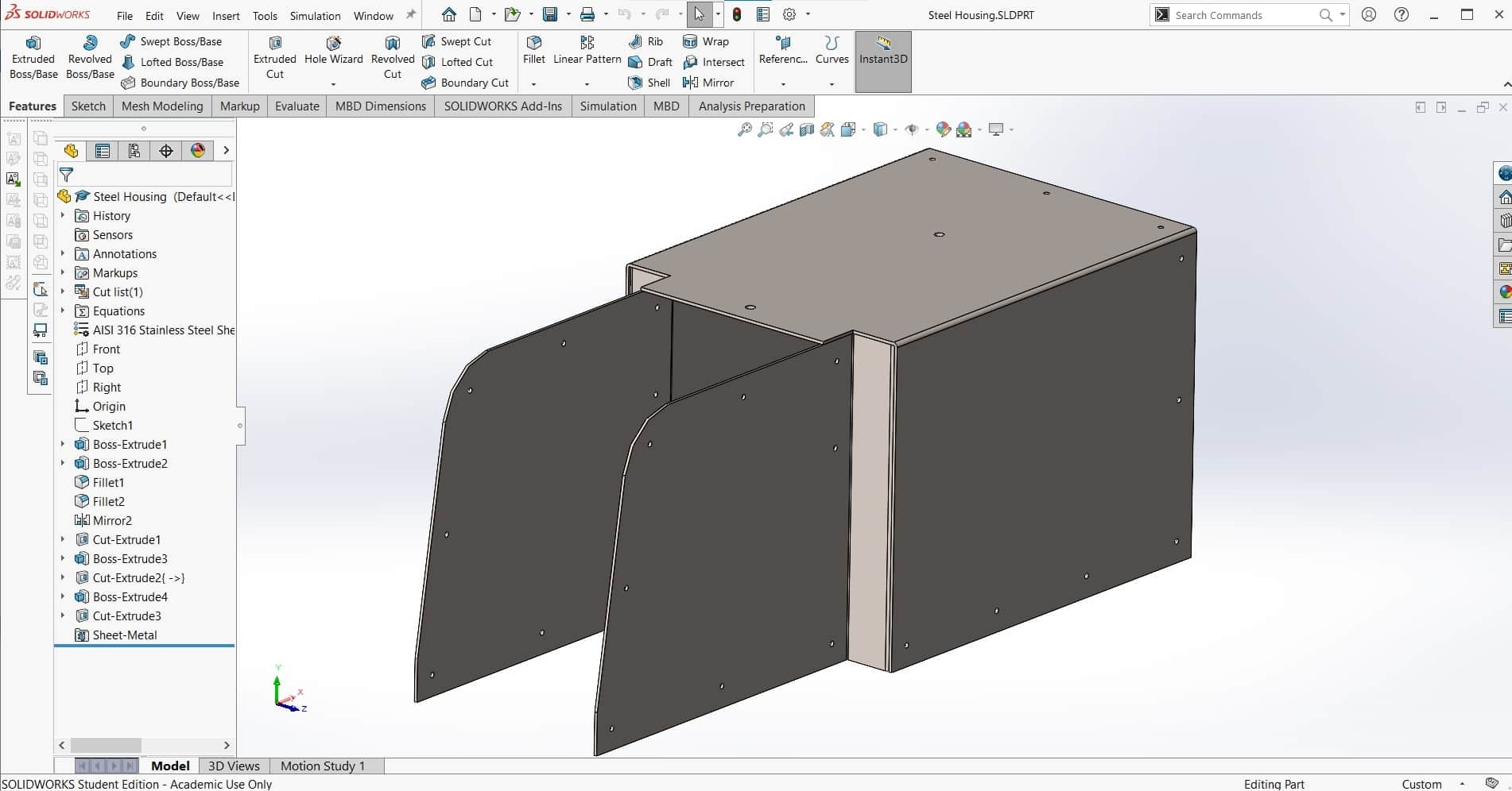
Leen suggested using sheet metal for the housing instead of wood. I don't have much experience bending metal and we don't have any special equipment for it in the lab, but it's a fairly simple part in terms of geometry, so I thought I would be able to figure it out using enough bar clamps lol. We had some 1 mm mild steel scrap in the lab that was perfect, so I designed the part with that in mind.
Cross Section
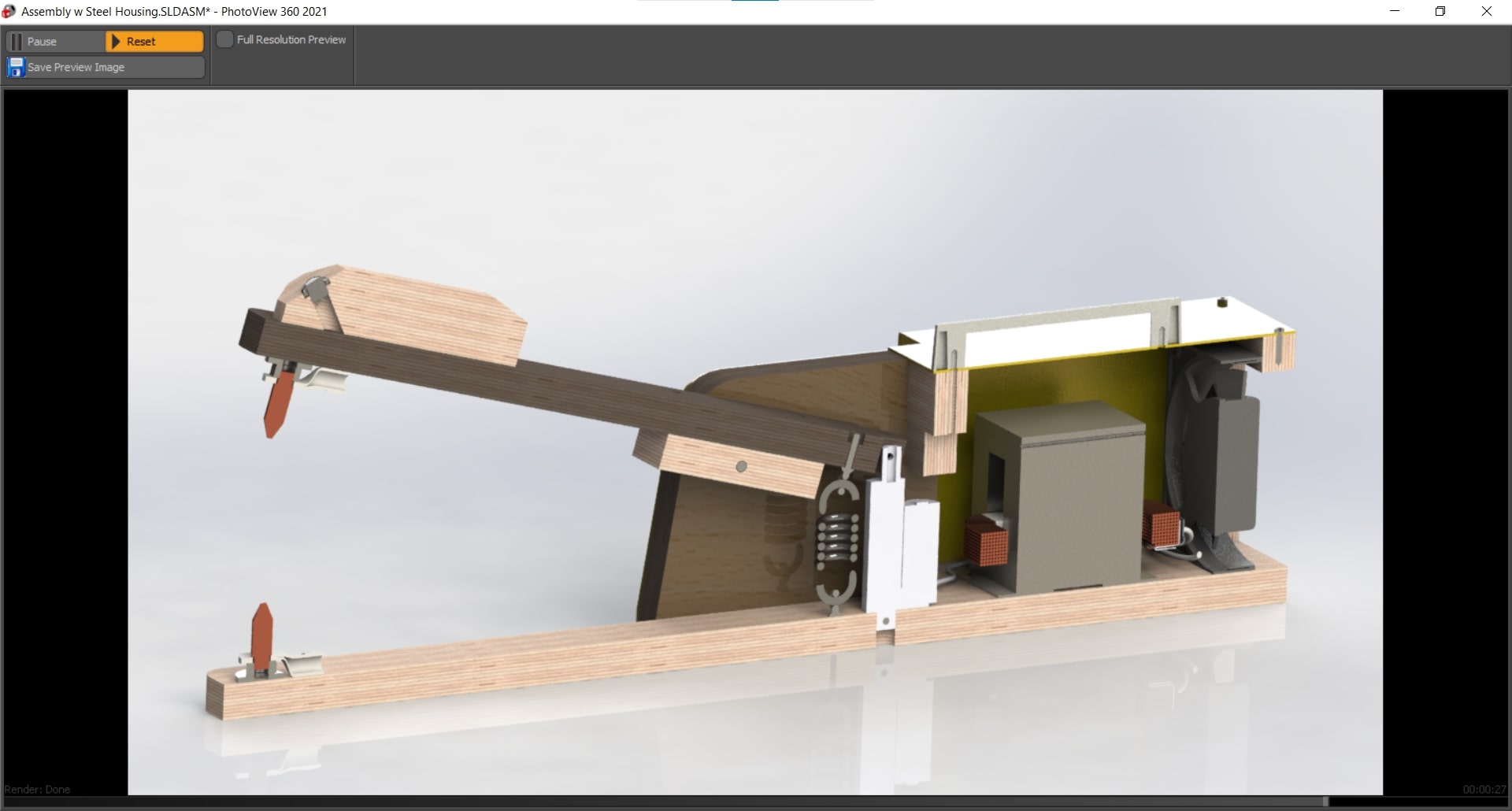
Finally, the assembly was complete. Here is a cross-section showing the inner workings of the welder as well as the relative arrangement of the components. In the end, I was really pleased with the results. The low profile steel housing was so much more aesthetically pleasing than the bulky plywood. Good suggestion Leen.
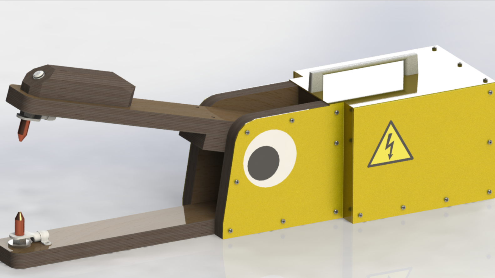
Googly Eye
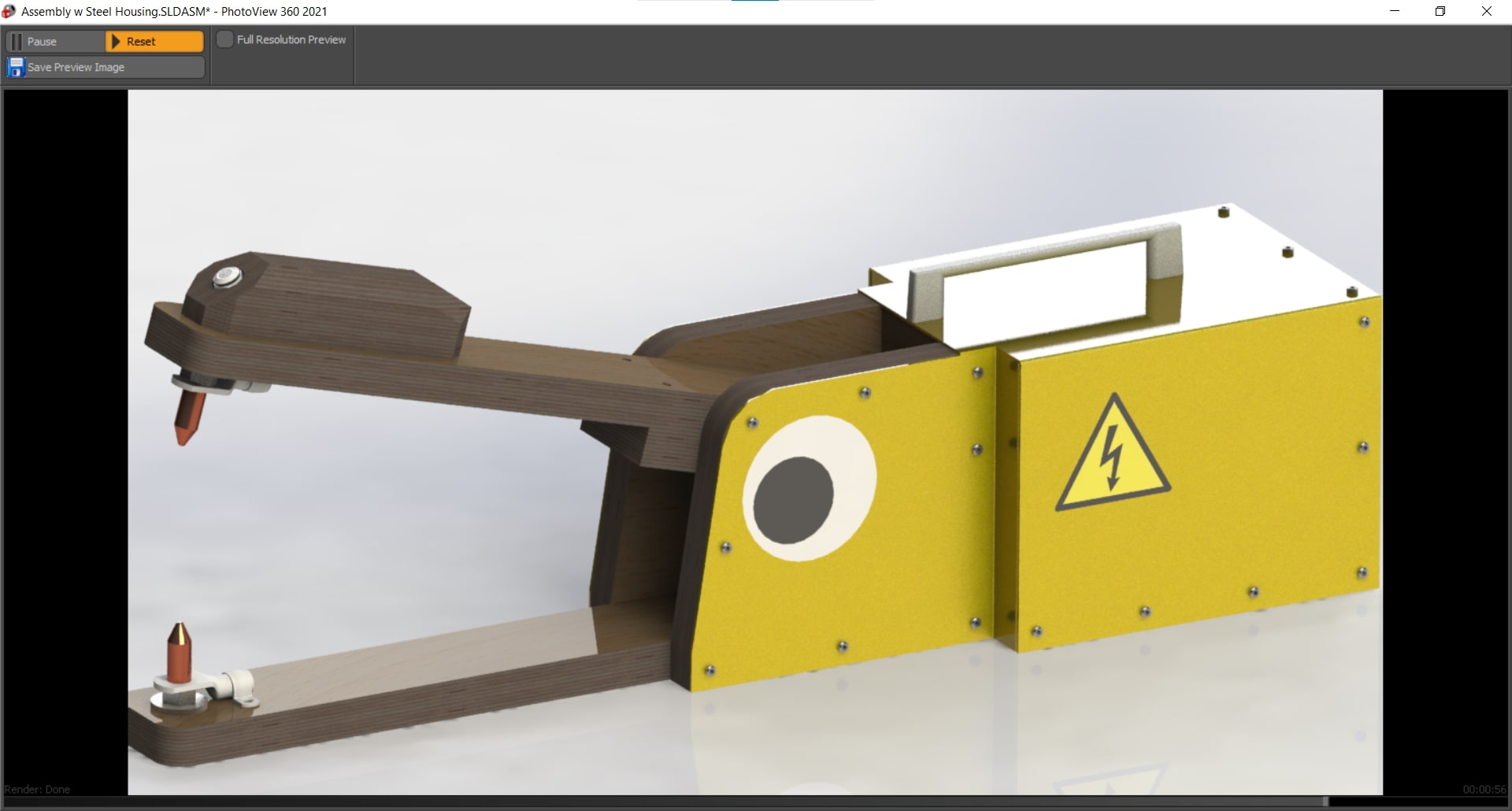
Here is the rendered assembly with all of the appearances. I also added a few stickers to give the device a bit more life. I can honestly say, this is the first time I have ever used CAD software to design a googly eye lol.
Description of the Design
Mechanism
The mechanical mechanism is fairly simple. It is essentially just two arms linked together with a pin joint allowing for a rotational degree of freedom. At the other end of the arms, sit the electrodes used for welding. There is a tension spring connecting the mobile arm to the base so the connection is always pulled apart unless the spring force is overcome.
Actuation
A linear actuator is positioned behind the spring. This will allow the foot pedal to be used to actuate the welding arms and to supply the energy during welding. When the foot pedal is half-pressed, the mobile arm rotates to make the connection between the electrodes; and when it's fully pressed, the current flows.
Automation
The bubble machine comes on automatically when welding as a warning sign to not look at the arc and as a distraction providing something else to look at. However, it can also be programmed to turn on and off on demand as well as to produce bubbles for a preset amount of time.
Functionality
Hopefully the function of the machine is obvious. We needed a spot welder, so we built a spot welder. Spot welders are exponentially more usable when they can be operated hands-free, so we added the foot pedal to improve the functionality of the device. Automated spot welders start at around 15k so we had no delusions about being able to achieve that level of quality in two weeks with essentially no budget, so we decided to go another direction for the automation side of the project and include a bit of whimsy that also serves a functional purpose.
Manufacture
Making Parts
Fabrication Plan
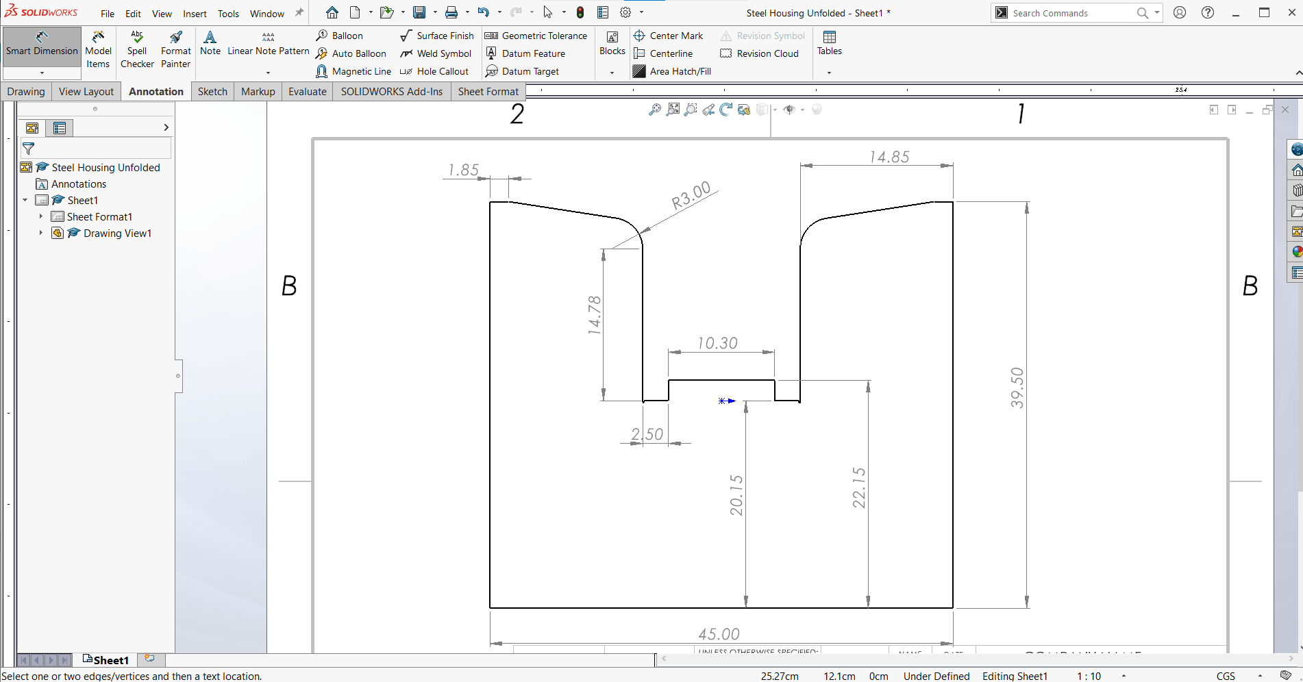
I began by using the Make a Drawing from Part function to generate simple drawings of my parts to make it easy to fabricate them. These are not formal engineering drawings, nor are they sufficient to make the parts using the drawings alone, but they were enough for me to get making.
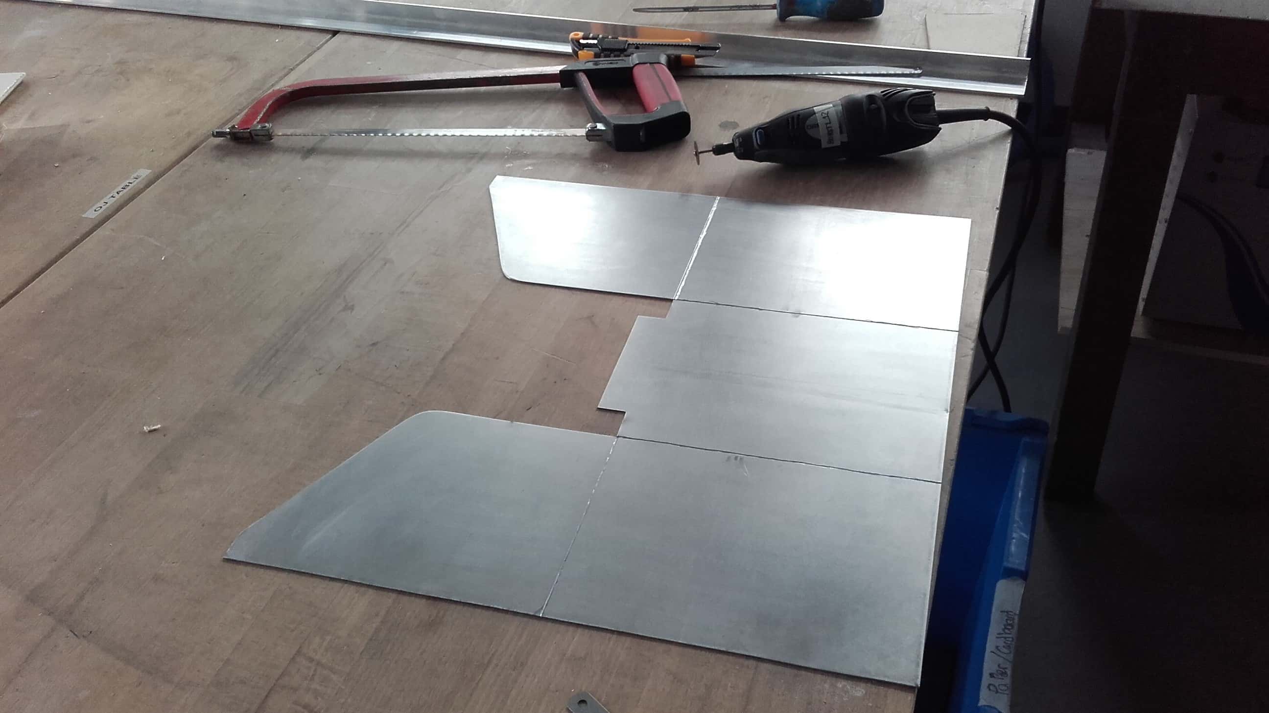
Waste Not, Want Not
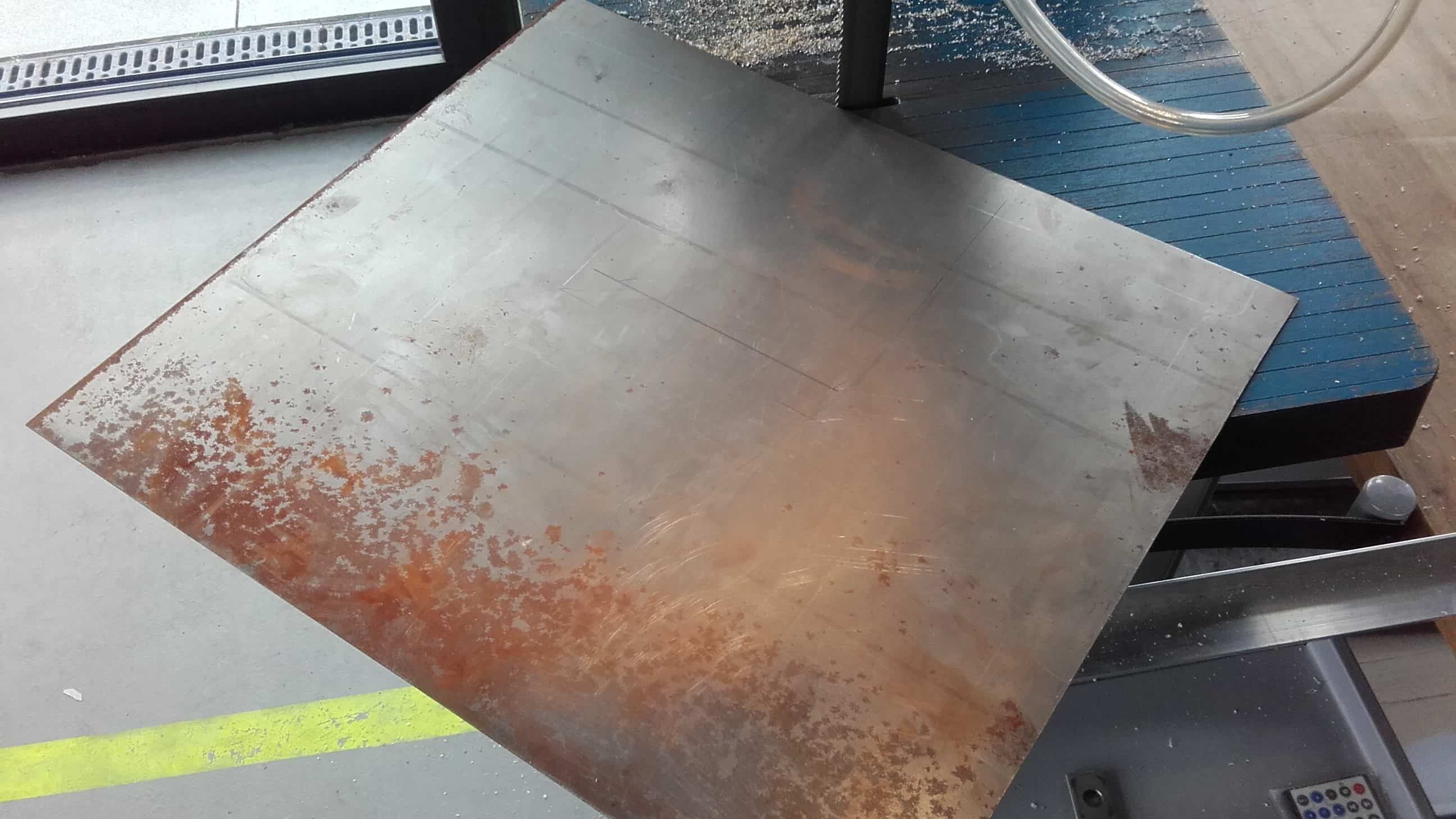
I found some 1 mm scrap metal in the lab. It was a little bent, and very rusty, but it was big enough and available, so I grabbed it and marked out all the straight cuts.
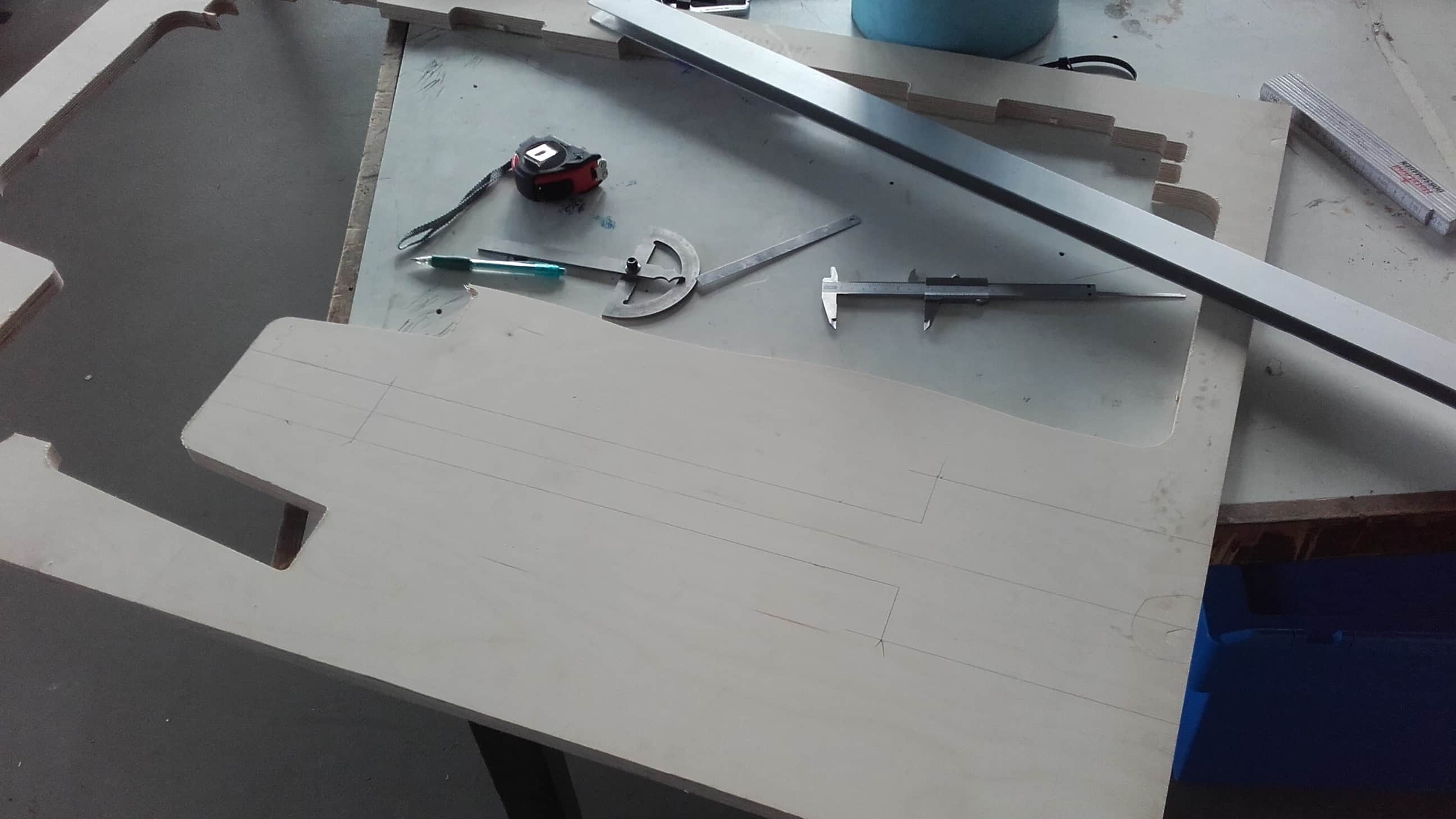
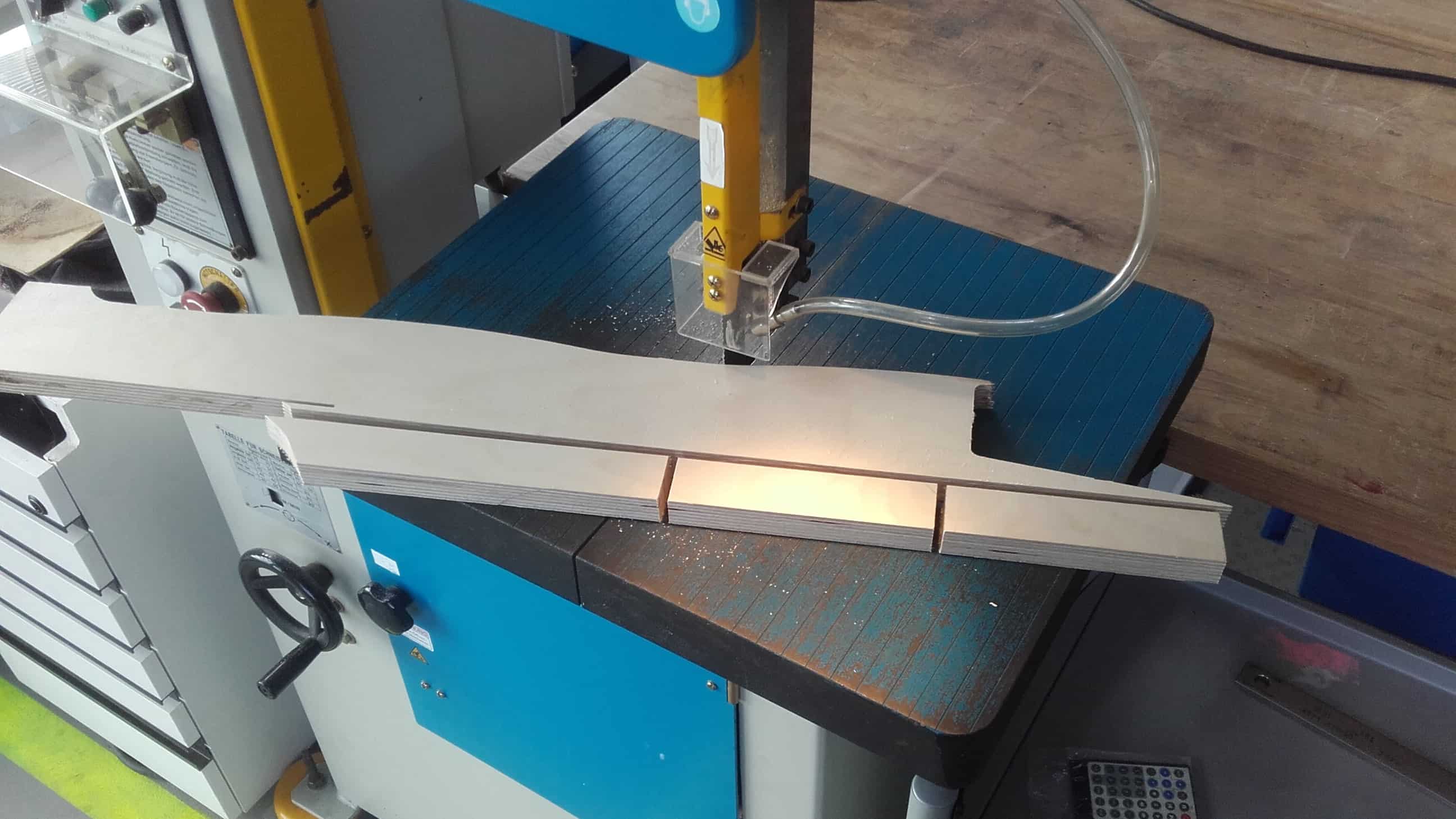
Cardboard Stencil
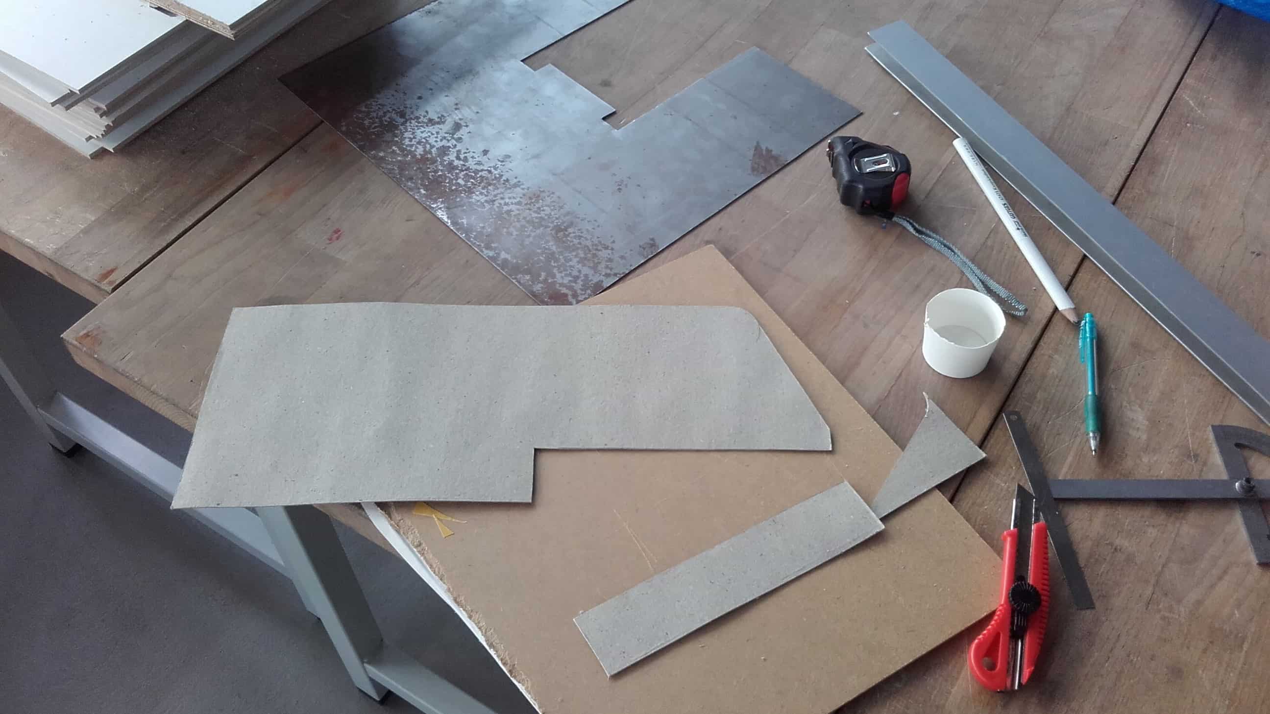
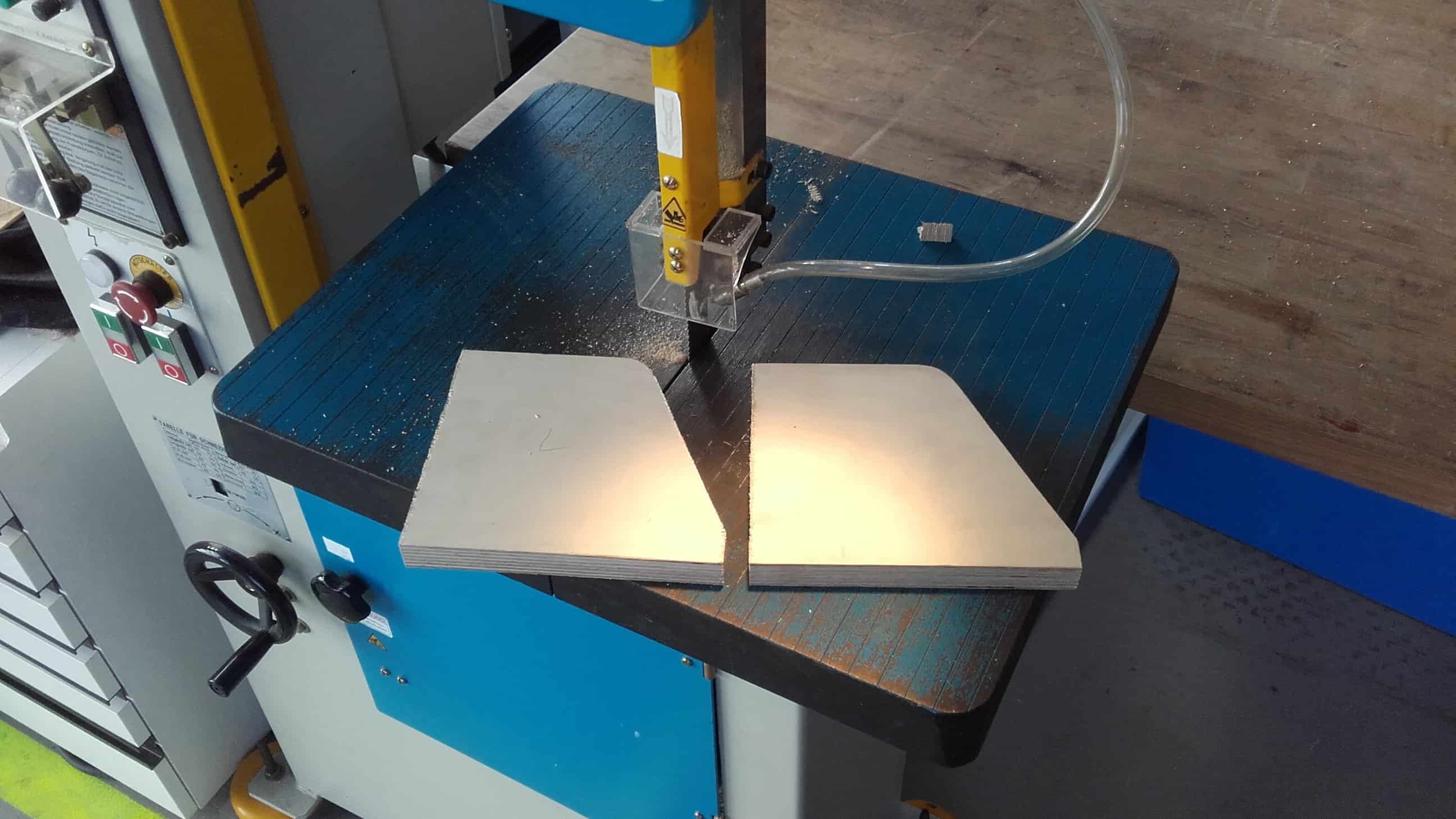
Then I cut the basic shape out on the bandsaw and made a cardboard stencil to transfer the more complicated geometry around the pin joint to the metal as well.
Cleaning Edges
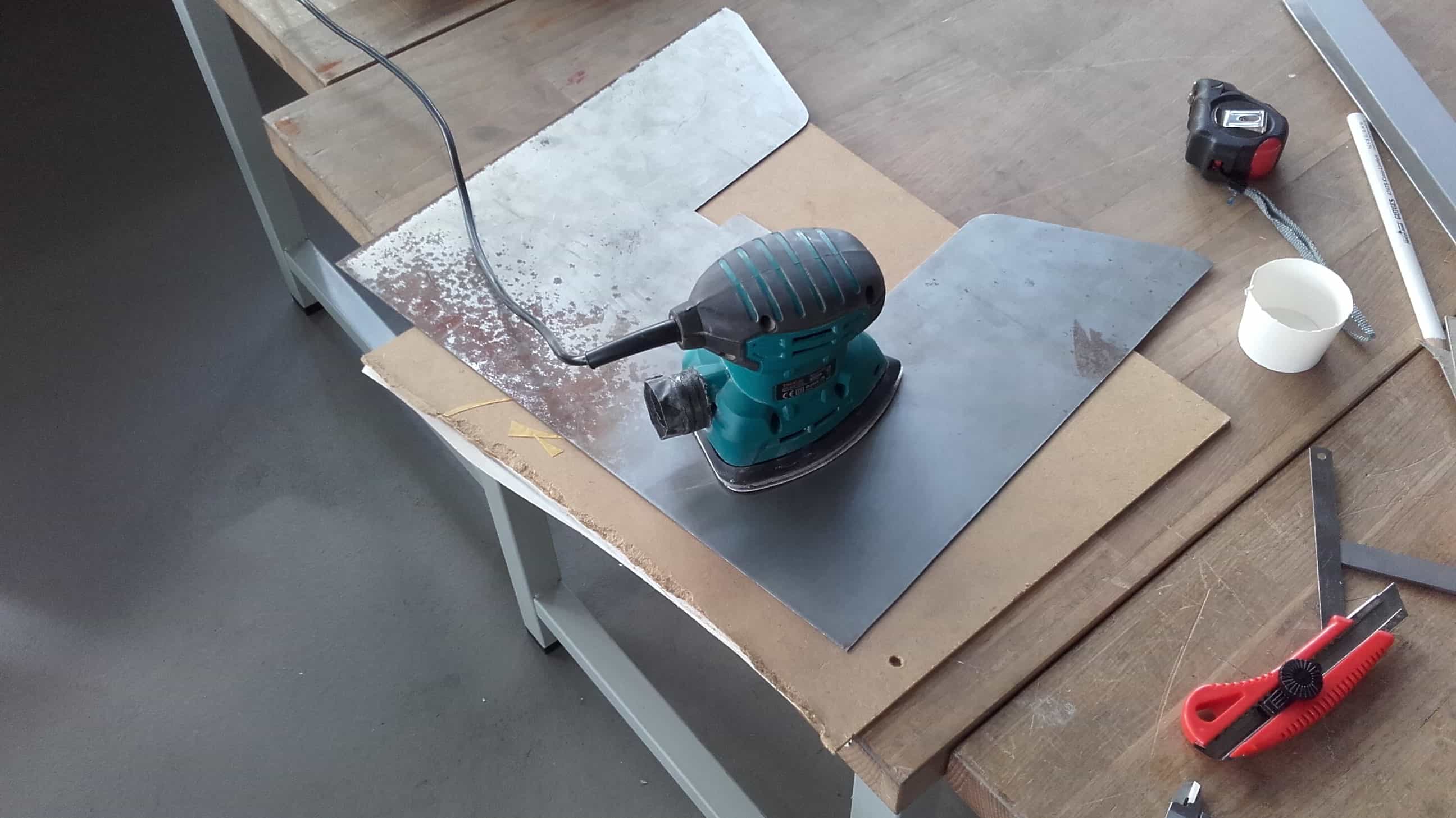
After cutting those out on the bandsaw as well, I used hand files to clean up the edges and I cleaned off all of the old rust using a palm sander.
Scribing
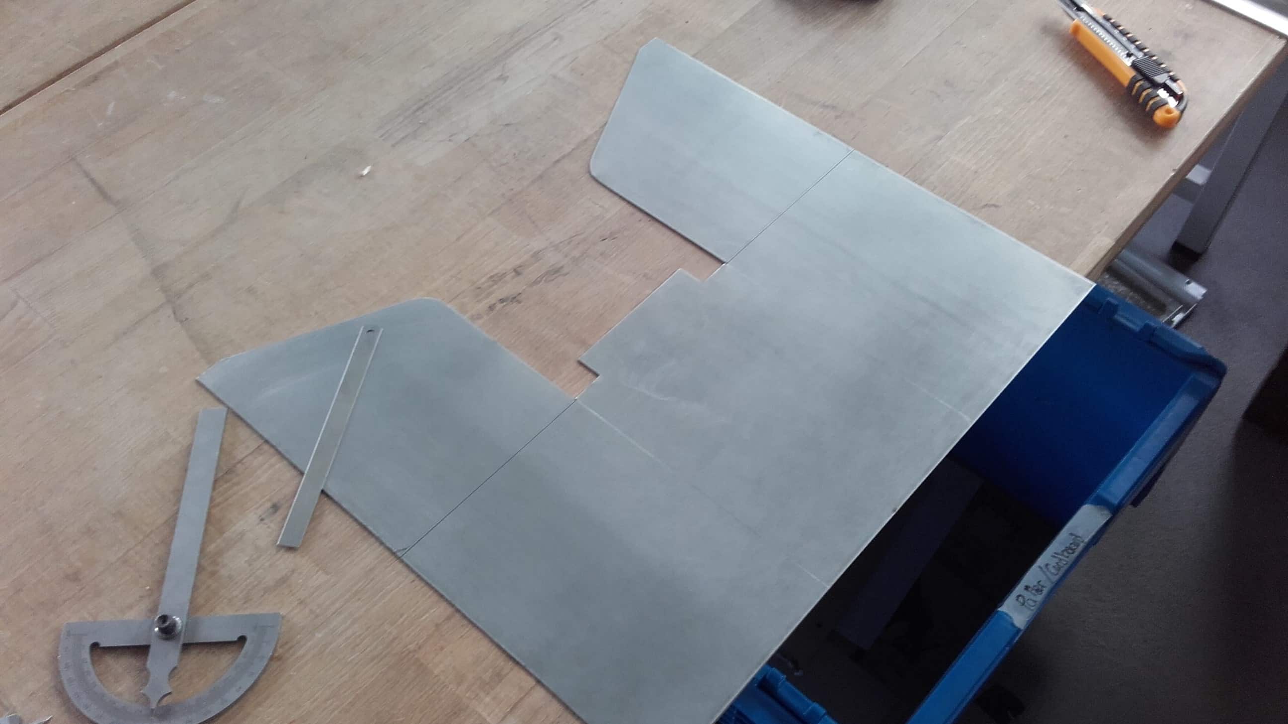
Finally the metal was the correct dimensions and looking good, so I carefully scribed out all of the lines where I would need bends to make the shape I wanted.
Bending Experiment
As I said before, metal bending is new to me, and we don't have a proper metal brake or any other bending equipment in our lab. I knew I would be tackling this job with nothing but clamps and willpower so I did a couple small experiments first.
Scoring with a Dremel
I got the best results when scoring the inside corner of a bend using a Dremel tool, so that is the method I chose to use for the real thing. With no guides or jigs set up for this job, it was a bit tedious to say the least. Anybody who has ever worked with a Dremel knows how they can get away from you, and I knew that would mean death for my bends, so I did this scoring very slowly and carefully. It wasn't perfect in the end, but it was the best I could do.
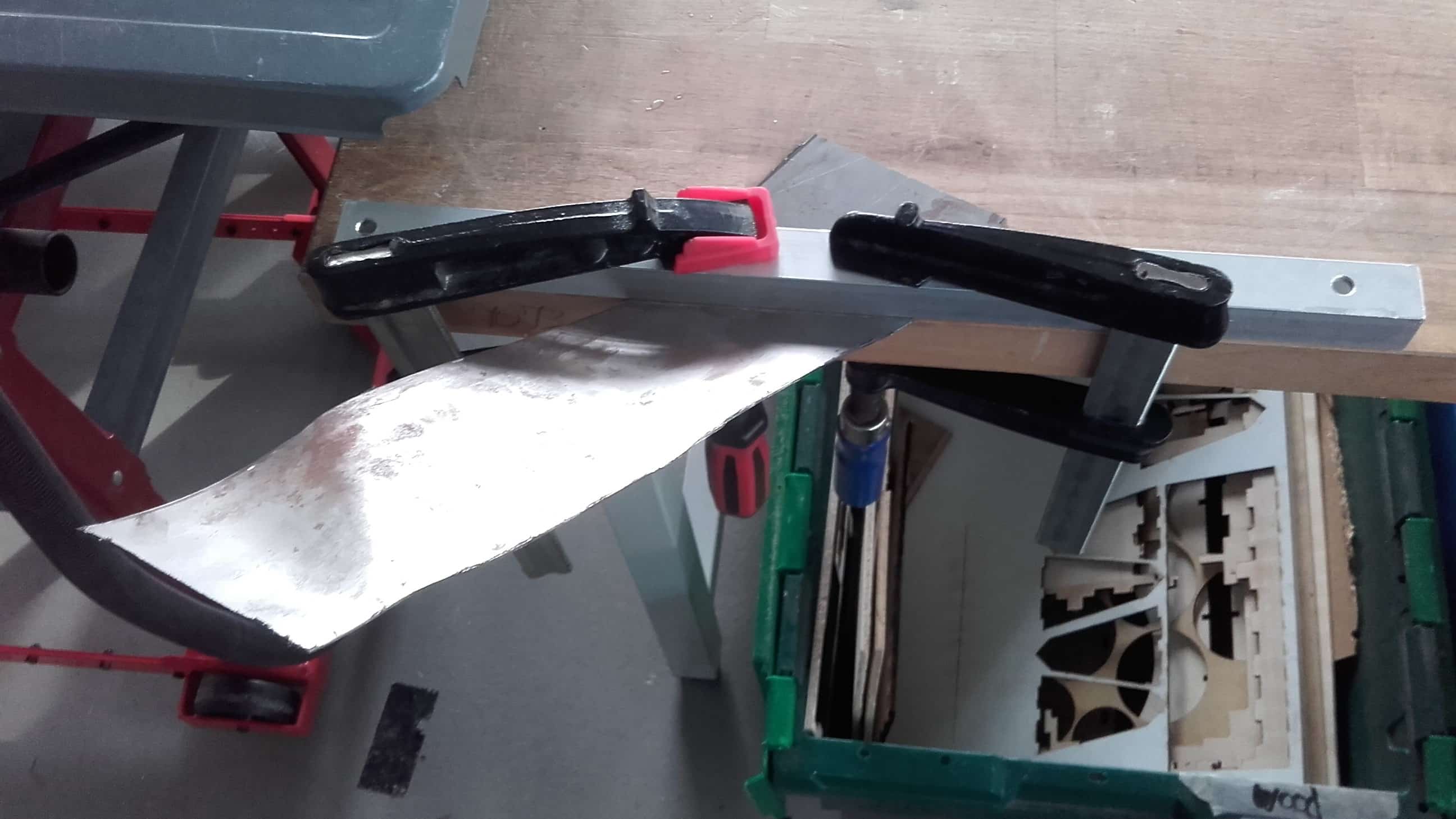
Bending Real Thing
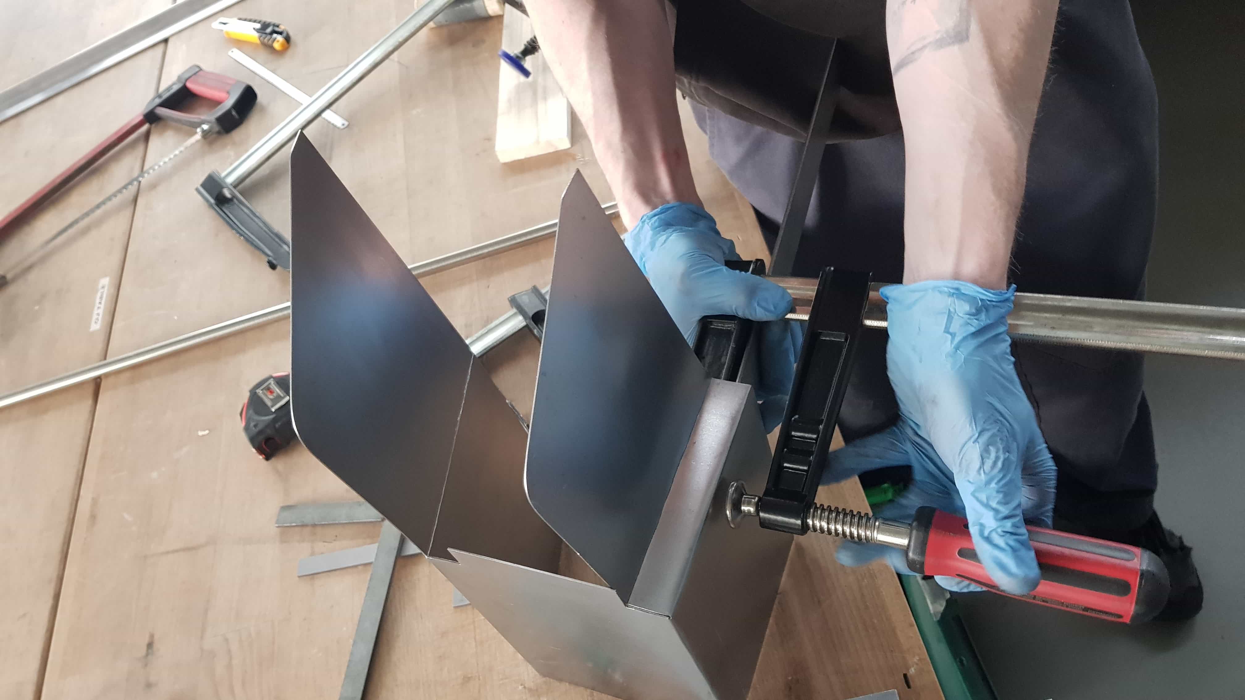
Then I very carefully started bending. This was a slow process with a lot of repositioning of clamps and bracing blocks. I also used pieces of angle iron and aluminum square tubing to assist in the bending, both for the square corners, as well as for keeping plane surfaces plane while bending.
More Scrap Recycling
Once the bending for the housing was completed, It was time to start cutting wood. I found some suitable scraps leftover from the Something Big project and marked out my cuts. It would have been easier to use new lumber, but I like the idea of this machine being made entirely out of reclaimed materials and spare parts laying around the lab.
More Cleaning
Then I started cutting. I cut most of the parts on the bandsaw, and then cleaned them up with either the palm sander, or the belt sander.
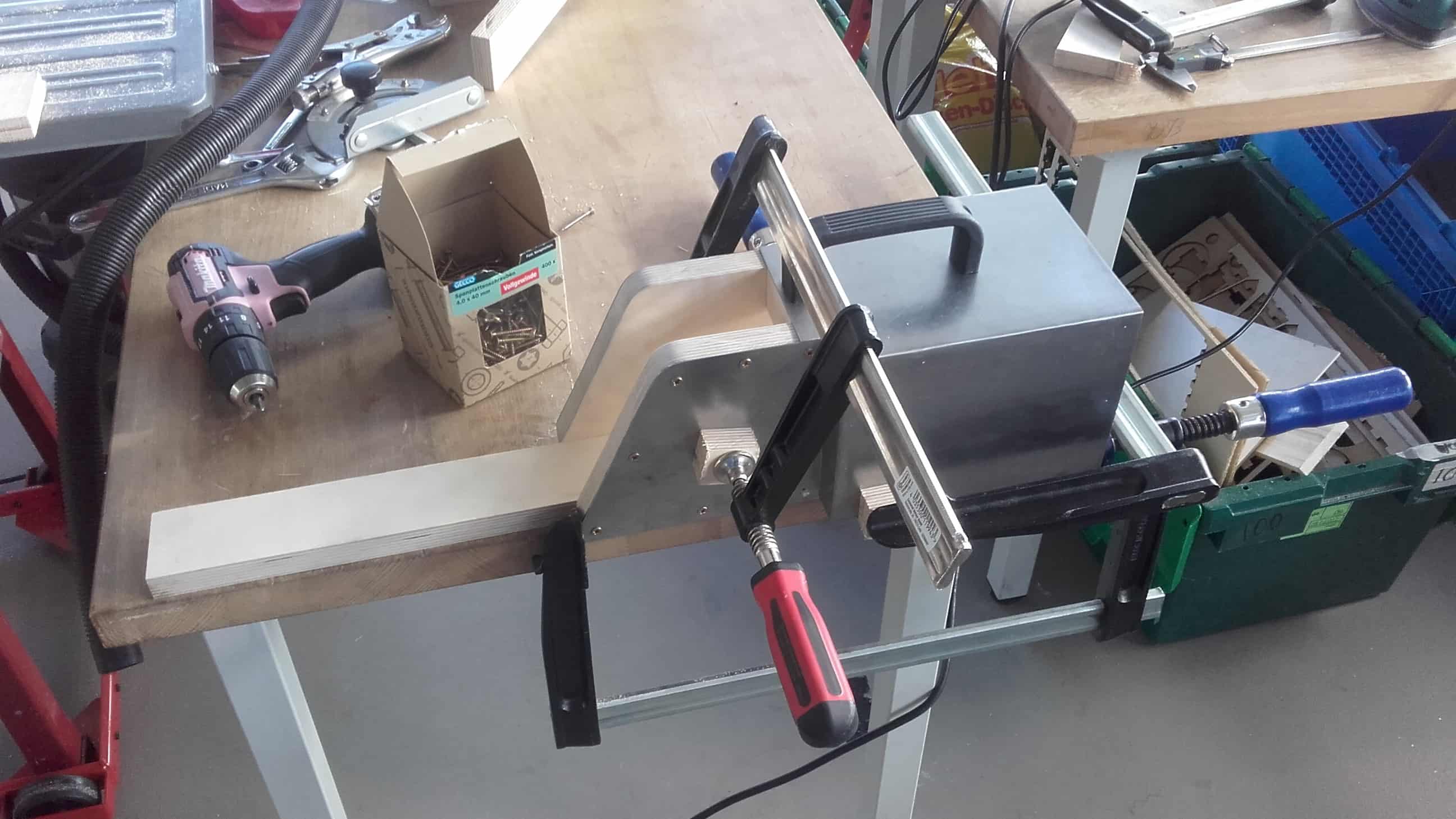
Clamping to Drill Holes
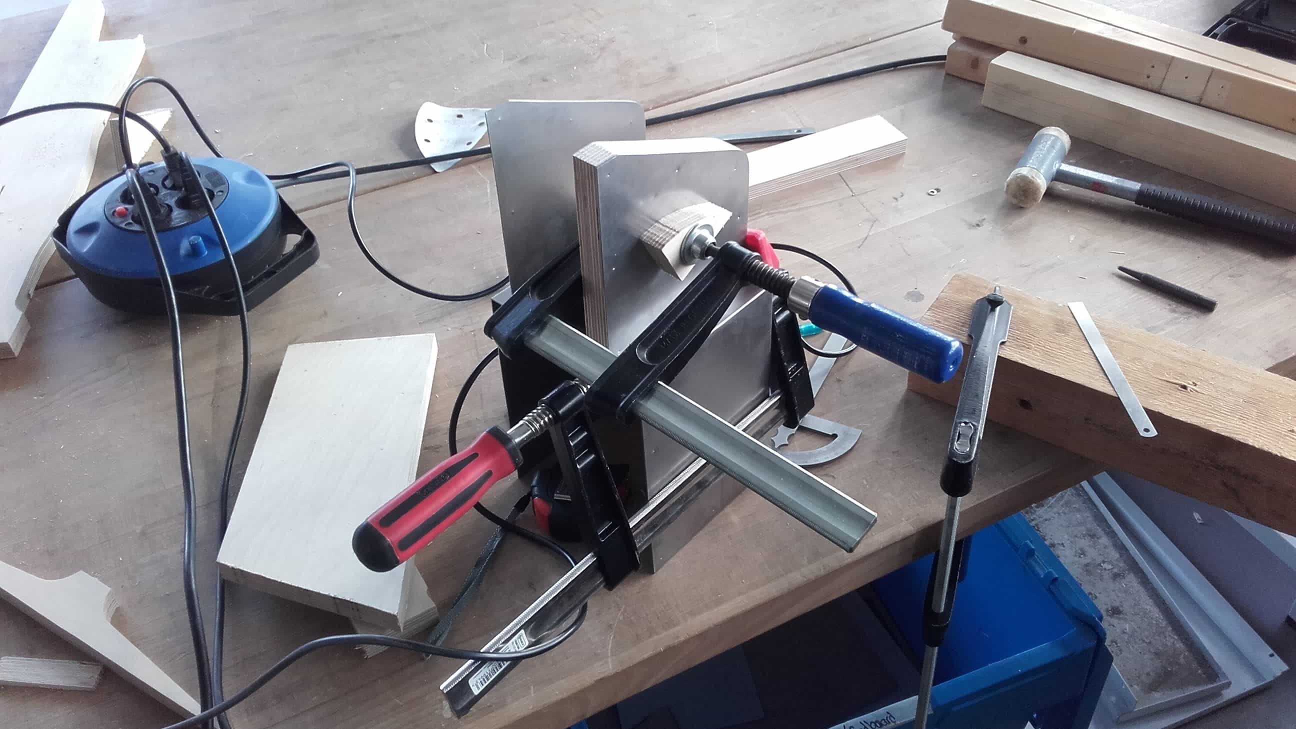
Then, using many clamping setups once again, I secured the parts where I wanted them so I could drill the holes for the bolts and screws that would eventually hold the device together.
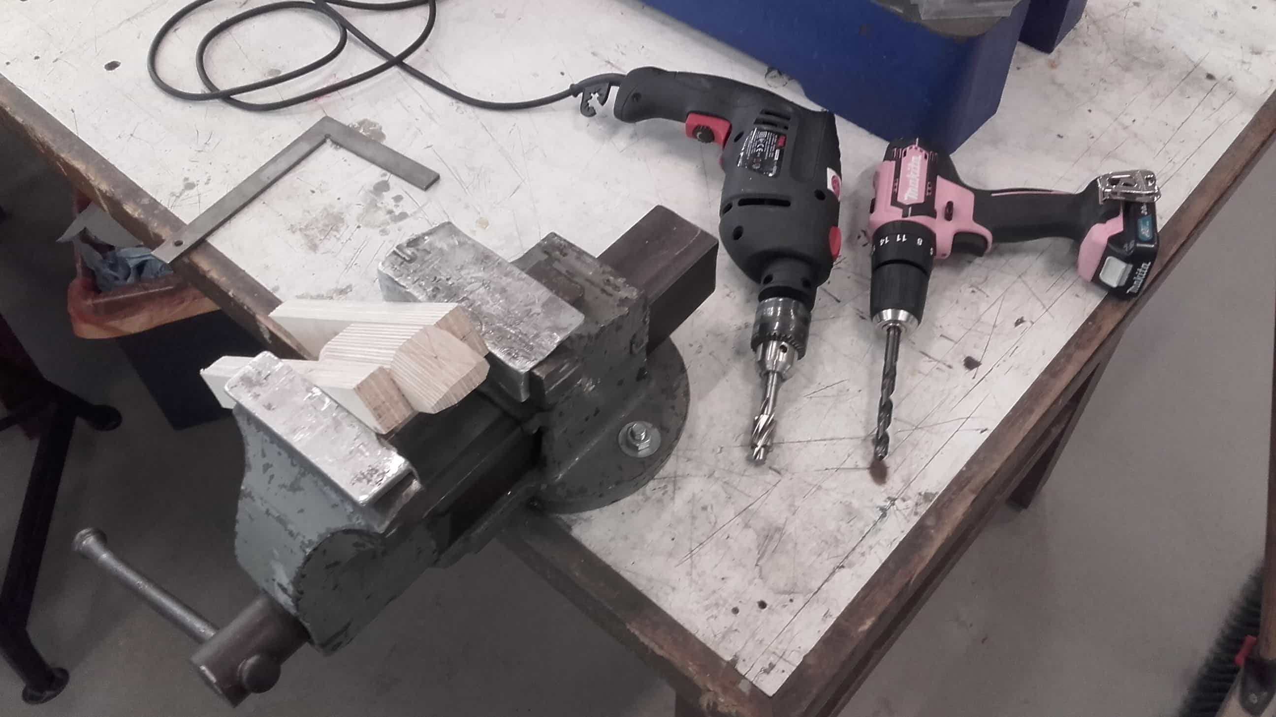
Drilling Holes
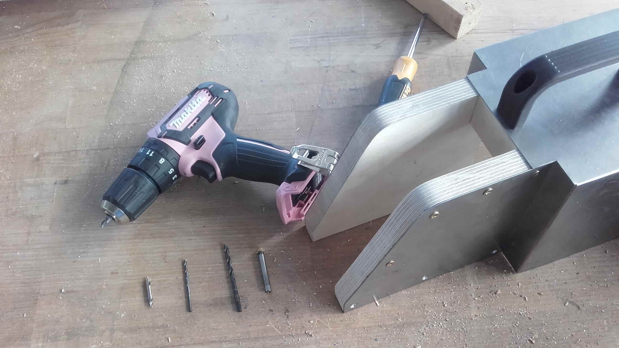
For every hole, I used a center finding bit to start the hole in the steel, then a 2.5 mm bit to drill the through hole into the wood. This was followed by a 4 mm bit only through the steel, and then a chamfering bit on the outside of the steel to allow room for the countersink on the screws. In the end, the screws fit really nicely, so I am glad I took the time to do the extra steps.
Sanding Edges
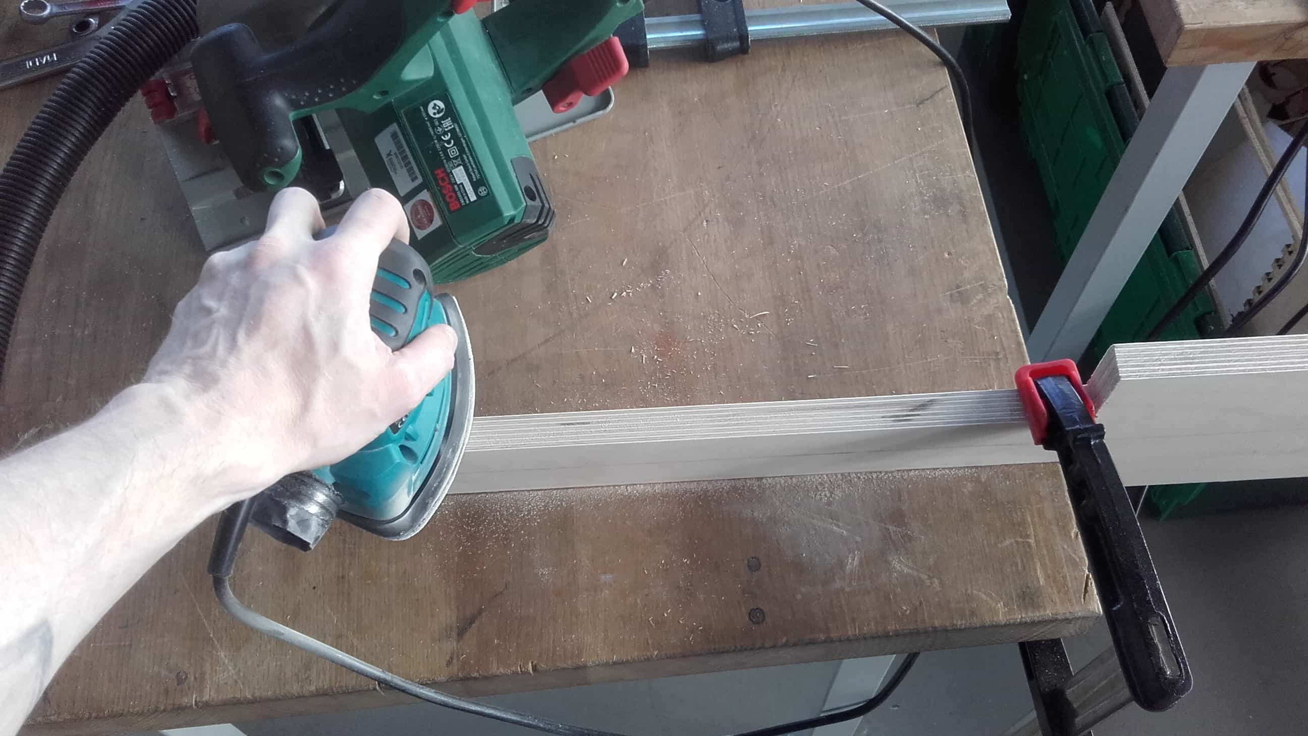
Finally, it was time to get all of the parts cleaned up for the test assembly. Once again, I used the palm sander to clean up the bandsaw cuts as well as any other manufacturing marks.
More Clamping for Mor Holes
Then I carefully aligned the parts and used clamps to hold them in place while I drilled the through holes in the wood. Once again, this took many setups and a lot of time.
Handle Outline
For the handle, I started by marking out the general shape of the two halves and then cut the pieces out on the bandsaw.
Glue Up
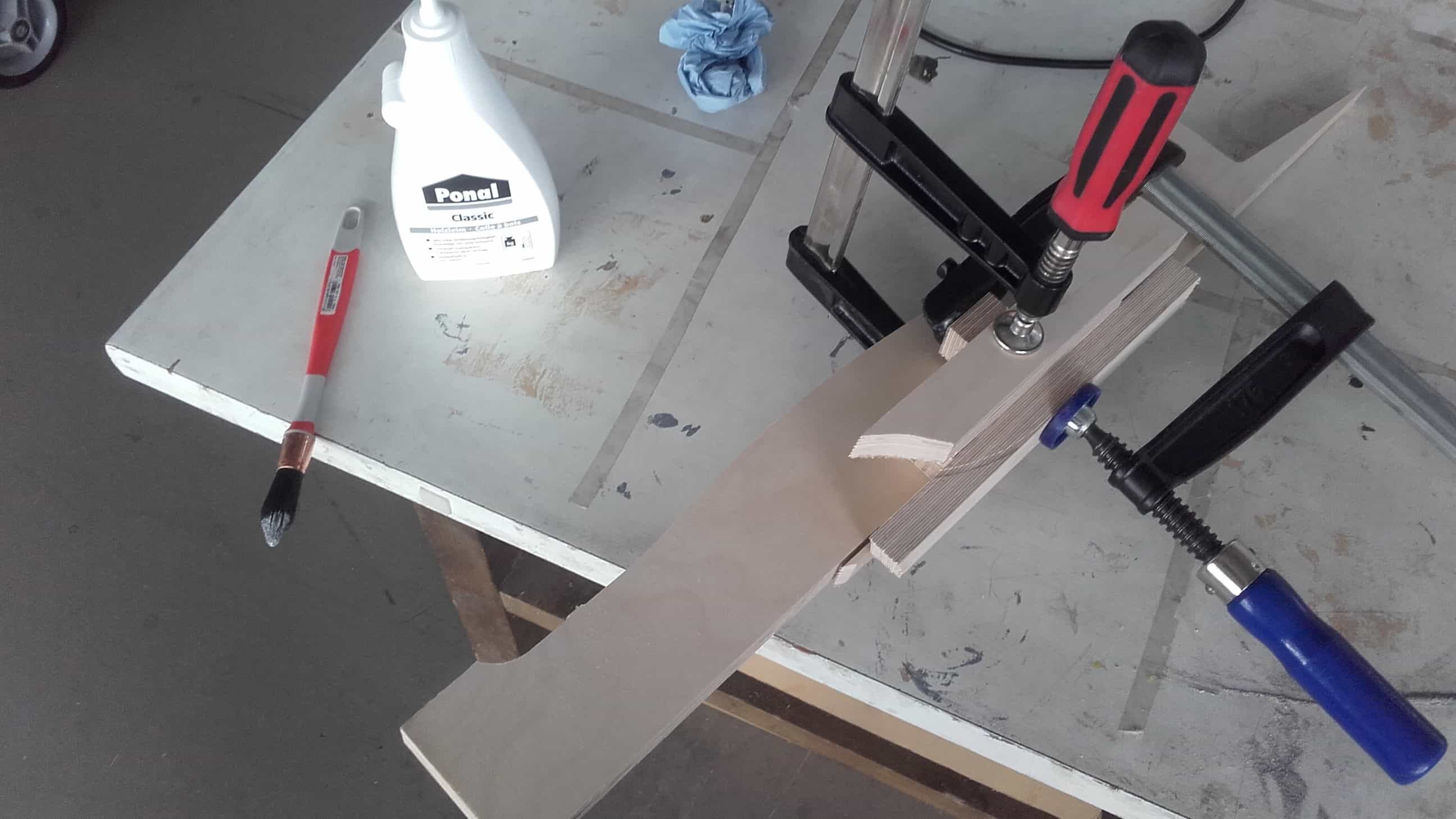
Then I glued the pieces together and sanded down the sides to clean up the bandsaw cuts.
Chamfers
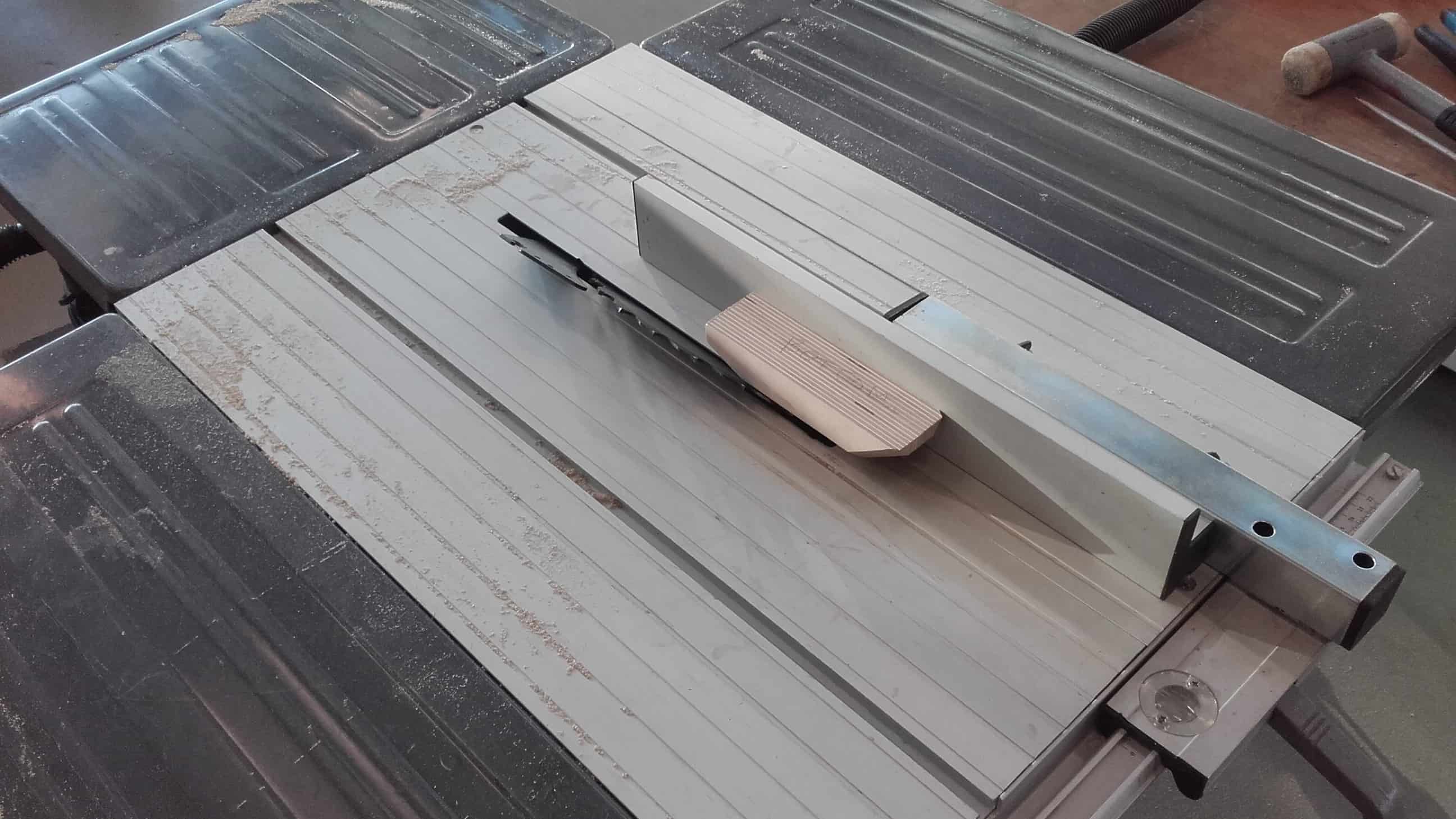
I used the table saw with a 45° angle to cut all the little chamfers.
Home for Pushbutton
And then I used a combination of a 10 mm drill bit and a counterbore bit to clear out the space for the pushbutton.
Pockets for Nuts and Bolts
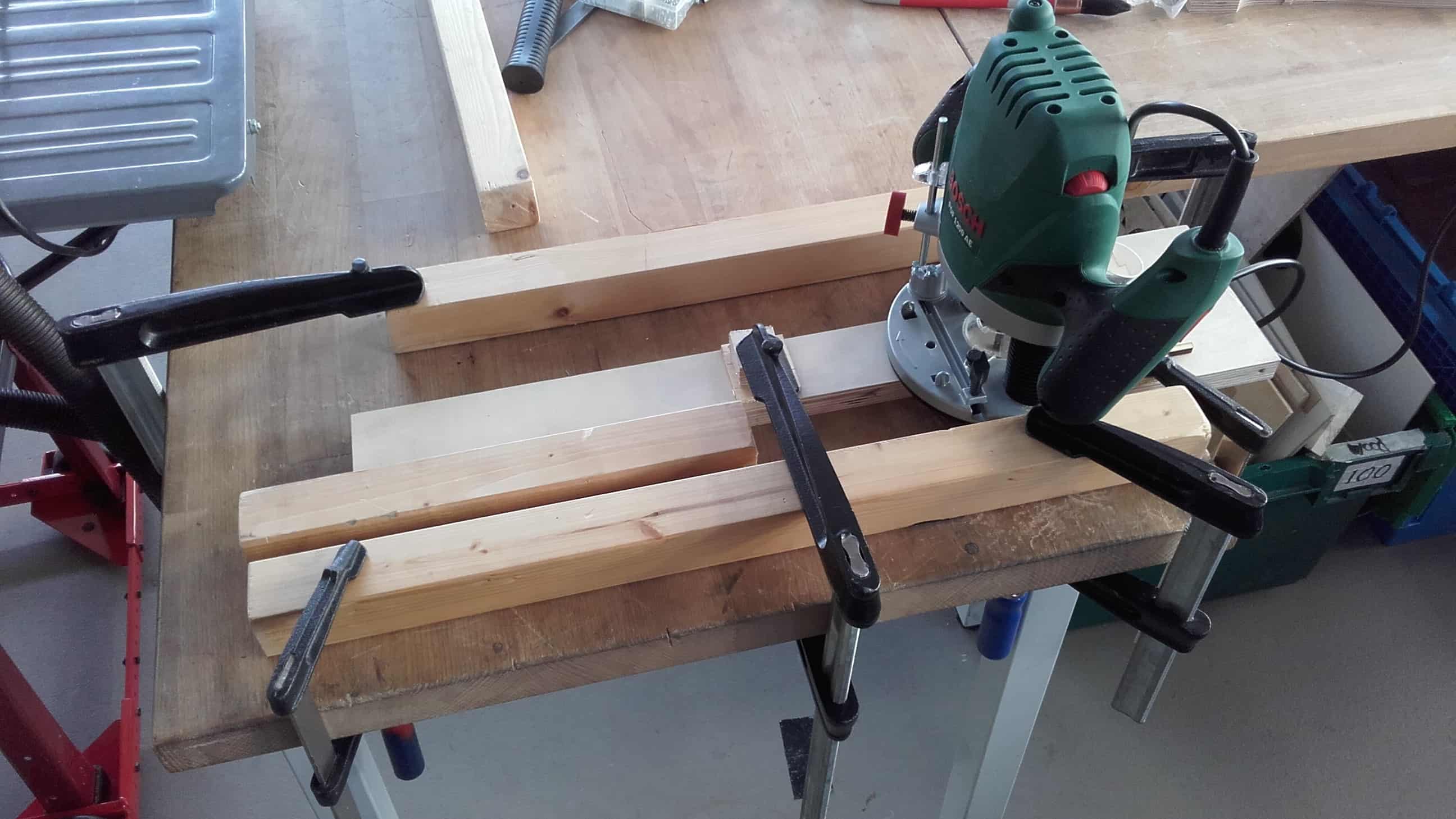
Then I used a router to hollow out a space for the linear actuator to fit, and to create a recess between the steel of the housing and the side panels for the nuts and bolts of the pin joints to reside.
Nearly Complete
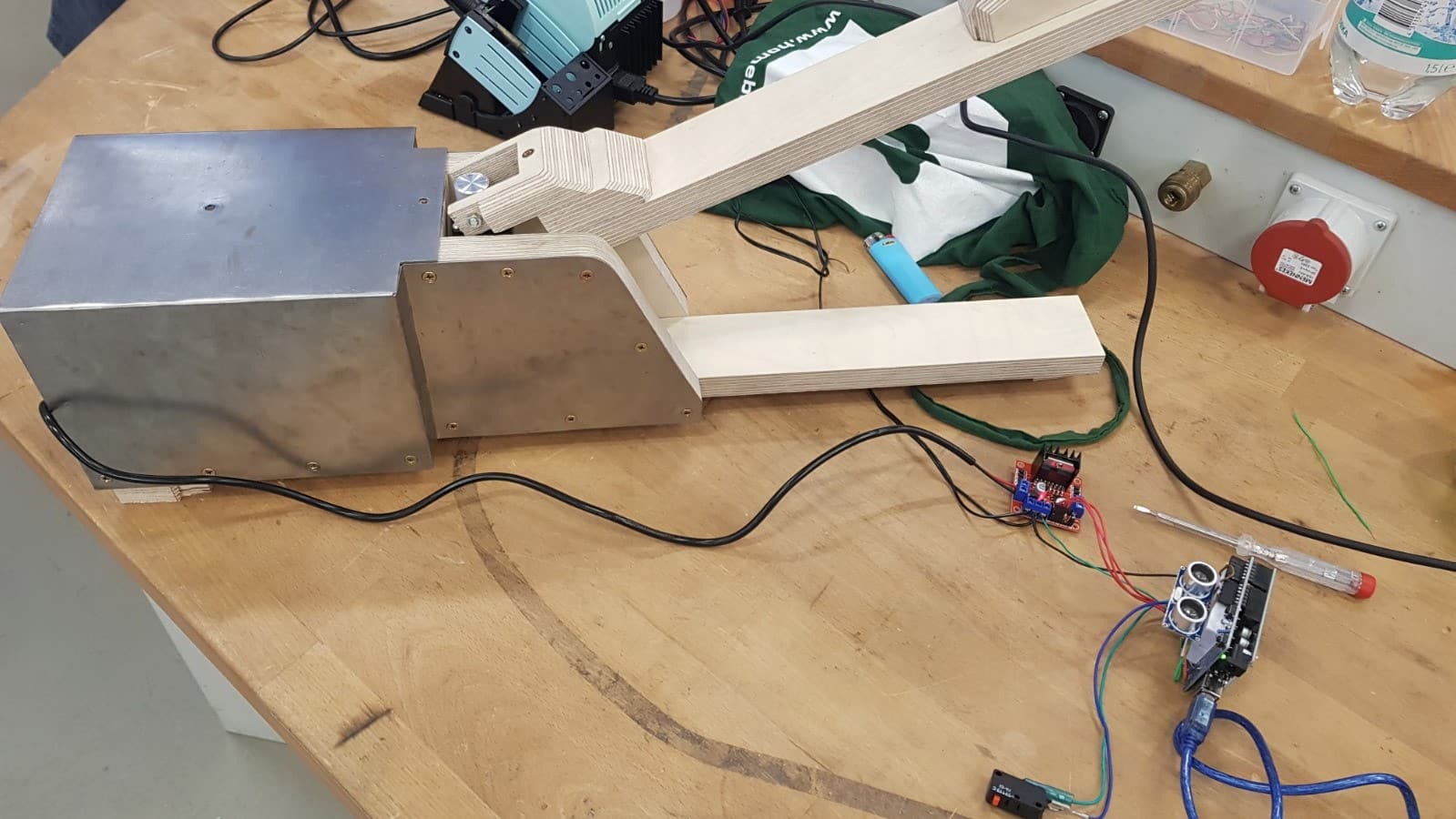
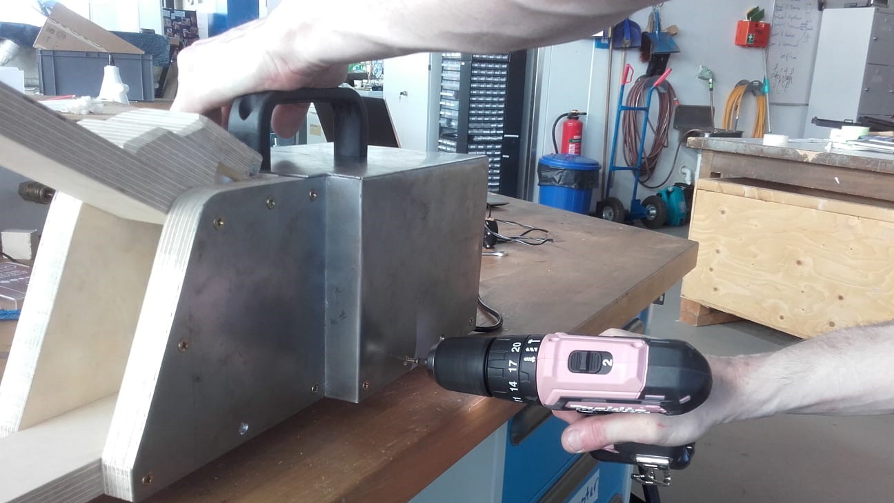
Once the device was finally all assembled, it was time for testing the controls. Unfortunately the linear actuator extended too far on the very first stroke and broke the upper jaw.
Triage
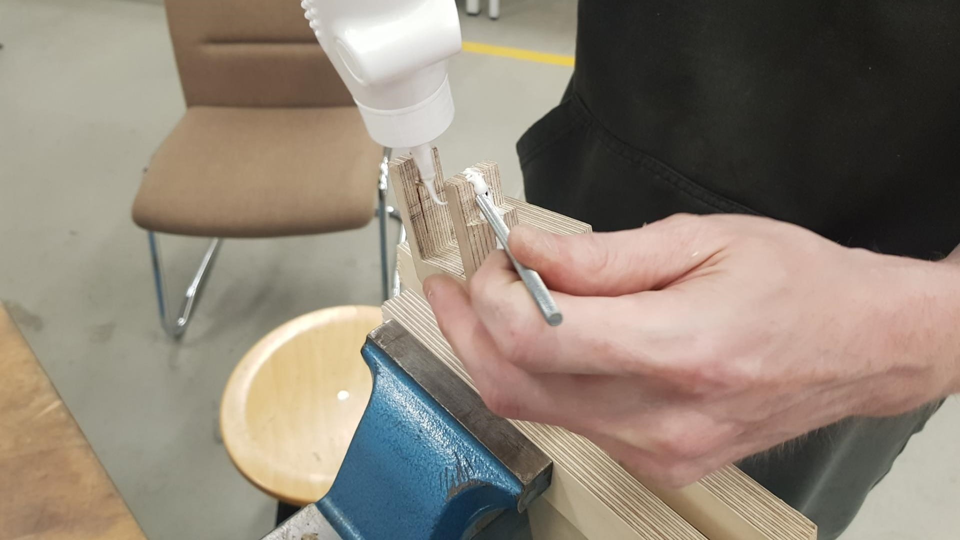
So I had to do some real time triage using wood glue and more clamps (the real heroes of this project).
Reassembly
When the glue was dry, I reassembled everything once again.
Front Side
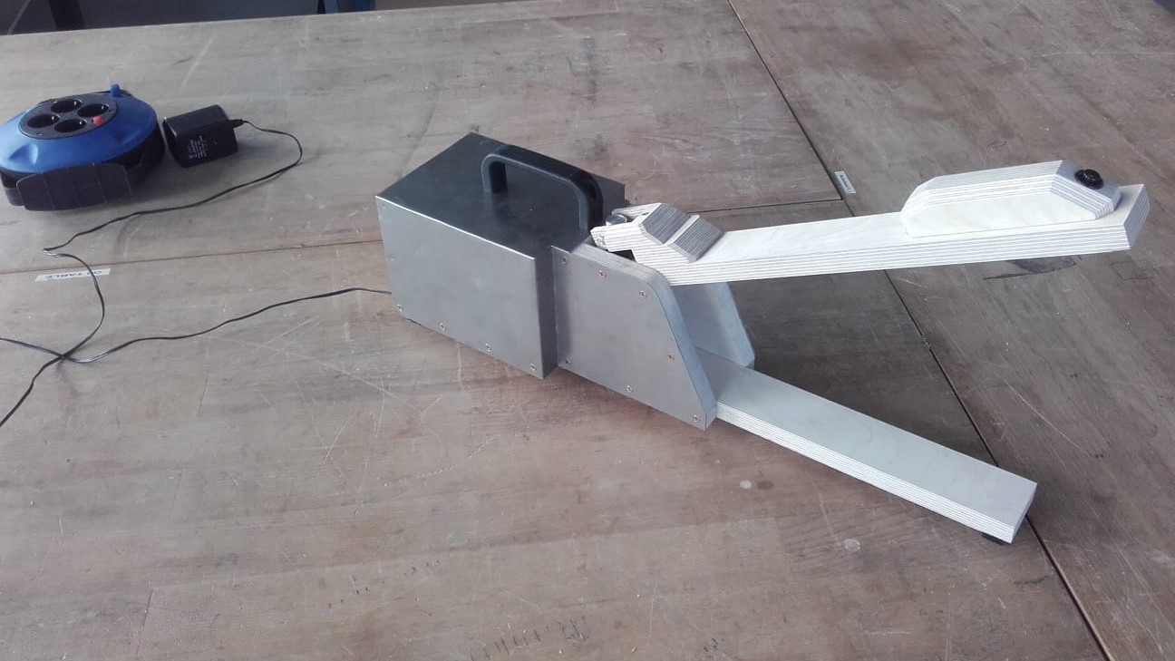
In the end, we had to come to terms with some major design changes, but overall I think my part came out ok.
Back Side
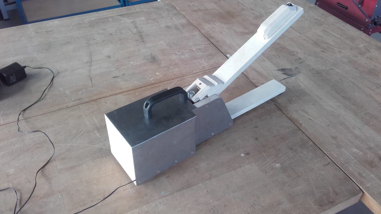
And all the electronics fit nicely in the back.