Leen Nijim
Assignment 12
Mechanical Design and Machine Design
Task
Our task this time was to work with our fellow colleagues as a group and design a machine with a mechanism, actuate it, and automate it. Aaron suggested we build a simple spot welder as someone in a DIY video on Youtube did. We liked the idea and decided to add an automated "Safety Feature" to warn others when the welder is being operated. So my part of this group effort was to make this safety mechanism work.
A couple of changed plans later, we ended up making our lab's very own Fartigator 3000 :D. It is, as Neil Gershenfeld so nicely put it, "A Thing That Does A Thing". And although my technical contribution remained as planned, the purpose of the bubble maker now is to make farts, be it locally produced ones, or remotely actuated.
What You Need for My Part of the Machine
- Cheap bubble-making machine.
- Two Arduino Nano boards.
- One MOSFET breakout board.
- A pair of transceiver breakout boards (nRF24L01+).
Files to Download
Hero Shots
Group Documentation
For the full machine documentation, please click here.
Proof of Concept
The bubble blower feature gets activated once the mechanism is actuated and Fartigator 3000 opens his mouth. It is remotely controlled and is to be placed either in his main body or somewhere else in the workshop.
All for Science
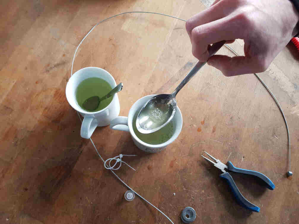
Before investing time in a major design, we had to learn the secret recipe of how to make bubbles. Since I wanted to build the bubble blowing mechanism from scratch, I wanted to know how best to design the bubbles ring. This resulted in Aaron and I having to do some experimenting.
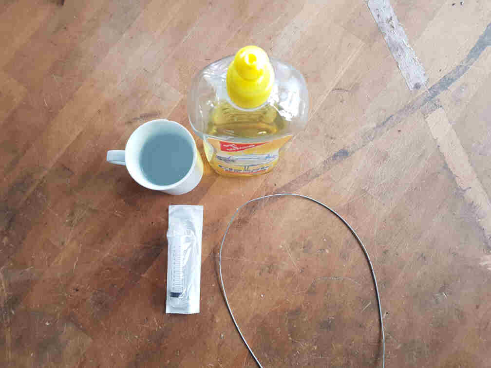
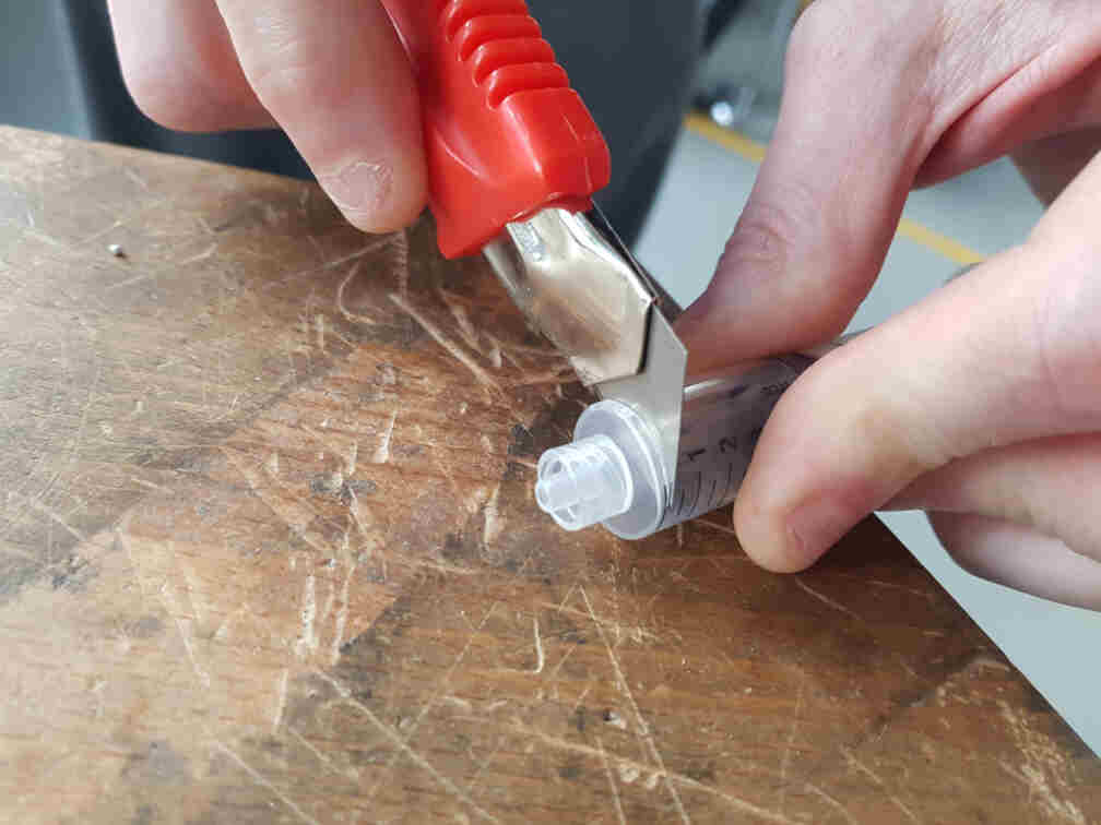
We wanted to use a syringe for our soap container and automatically protrude and retract the bubble ring that would be attached to the rubber seal of the syringe plunger. For that we had to sacrifice the syringe head.
Next came the bubble testing. We started out with a Bowden cable we found in the lab.
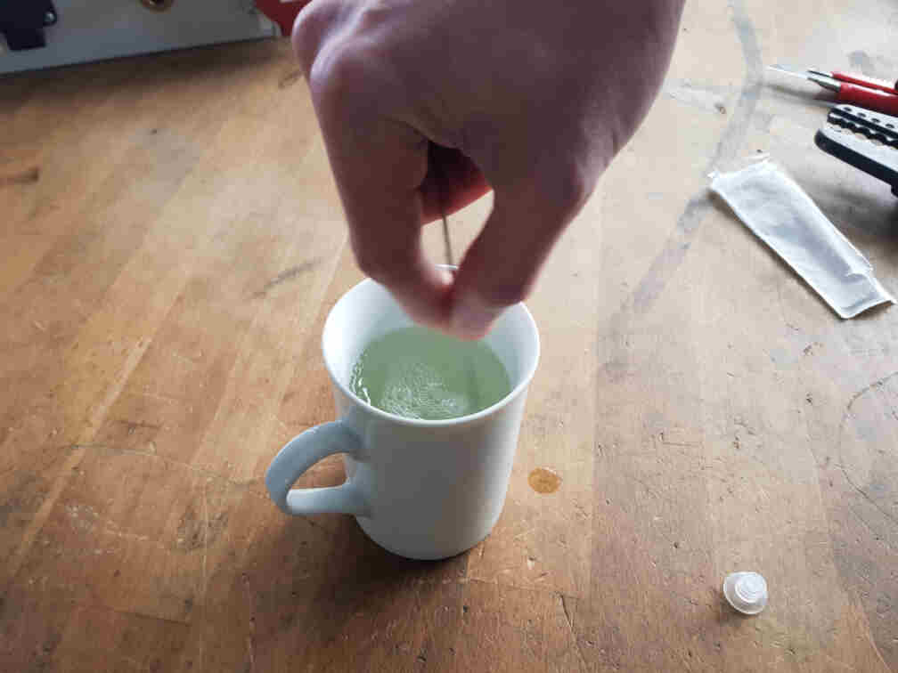
It proved a lot harder than anticipated to make bubbles, so we tried different sizes of rings, as well as some zip ties. Still had no satisfactory results, though.
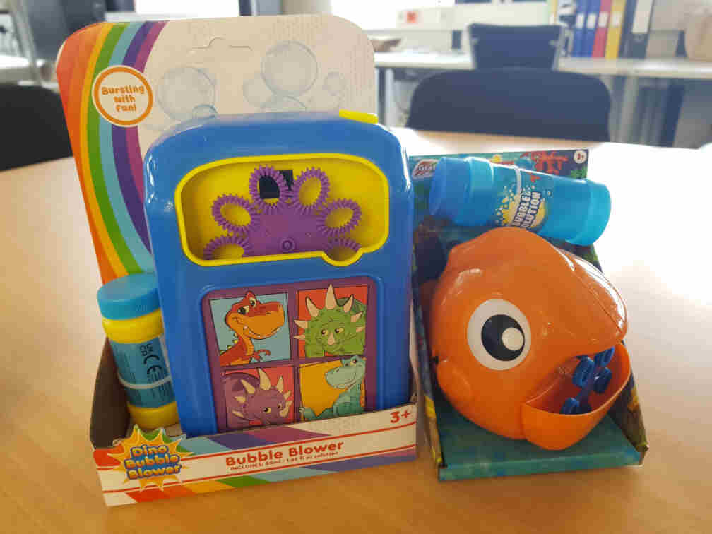
So we decided not to re-invent the wheel, and I went to a nearby shop and bought a pair of somethings :).
Getting Bubbles to Work
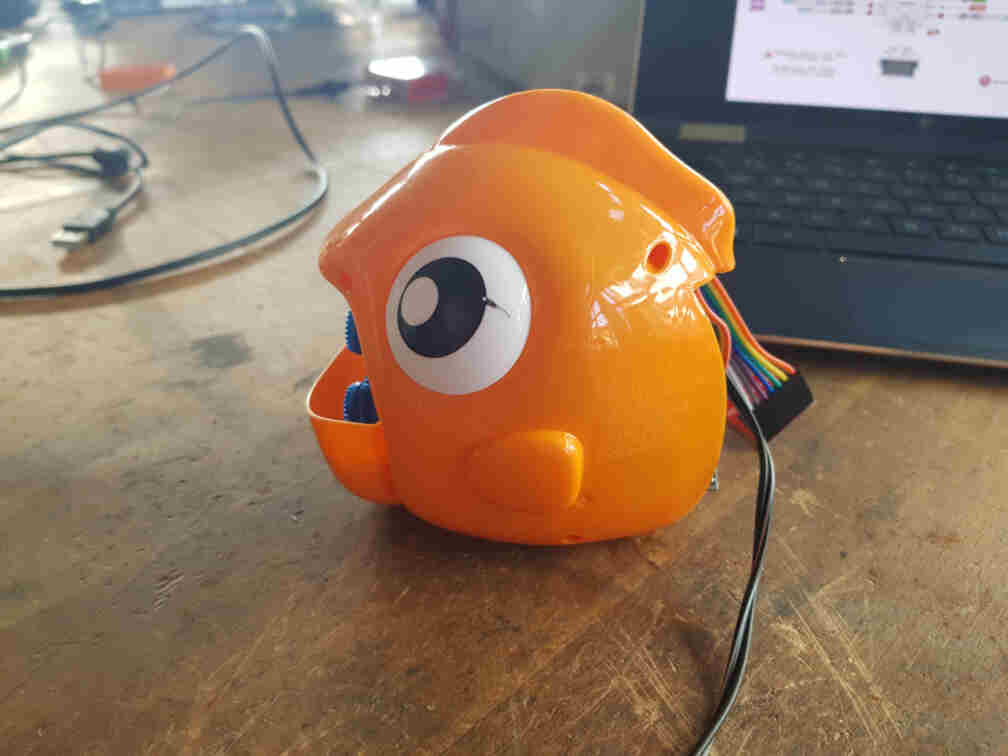
I chose to work on the fish and set out to convert it from a manually operated machine to an automated one.
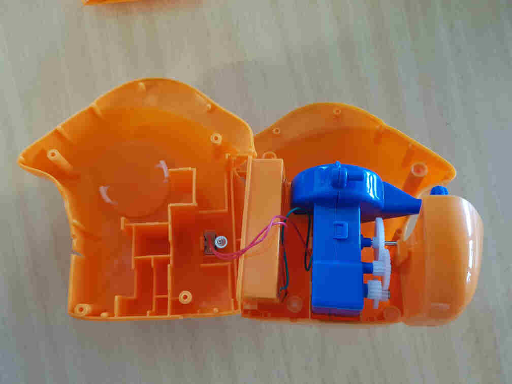
Opening It Up
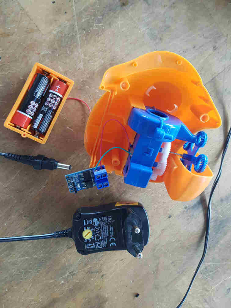
My first step was to open up one of the bubble makers and see what I can do with it. I went for the fish one, and as it turned out, it was a pretty simple design. A switch was connected to one of the battery terminals and the DC motor, and the DC motor was used via gears to operate the air fan and the bubble rings rotating wheel.
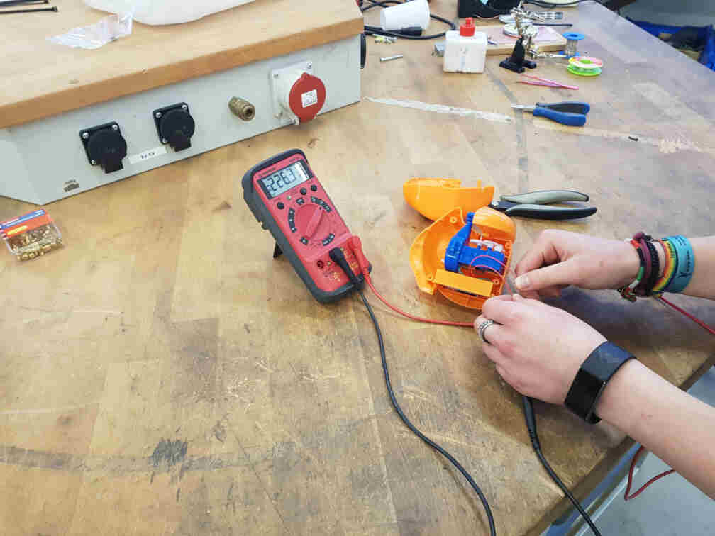
I then measured the motor's current consumption to help me pick which MOSFET to use to interface it with the microcontroller.
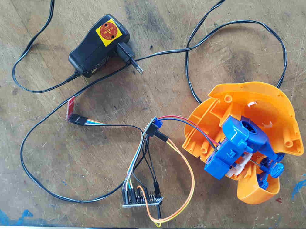
After I found out that one of the MOSFET breakout boards we have in the lab works, I connected it to the motor and used a power supply to test it. After that was successful, I looked through the lab for a transformer to supply the motor and microcontroller with enough power and found one.
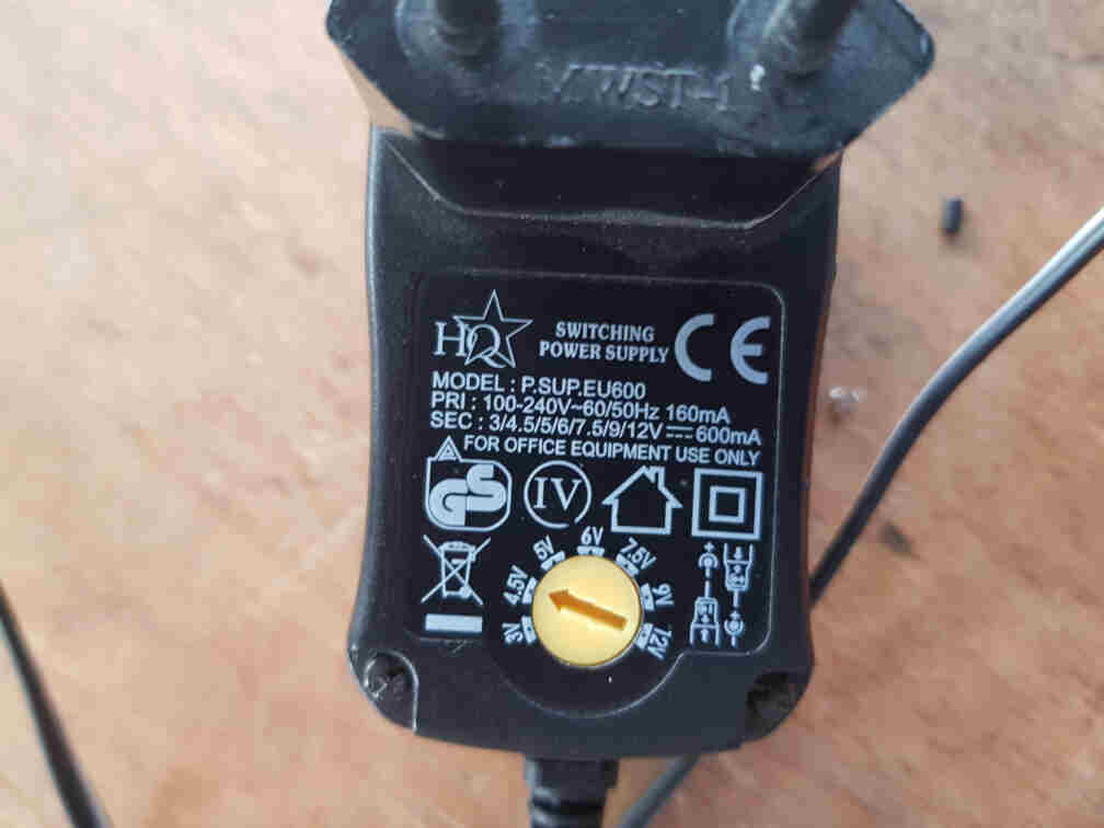
I turned the knob to 4.5 volts as a compromise between the arduino (5V) and the bubble maker motor (3V) because I didn't want it to turn that fast and didn't want to complicate the circuitry by adding a voltage regulator.
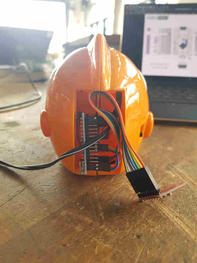
I then needed to attach the microcontroller pin headers to the transformer's cable and the DC+/- MOSFET terminals.
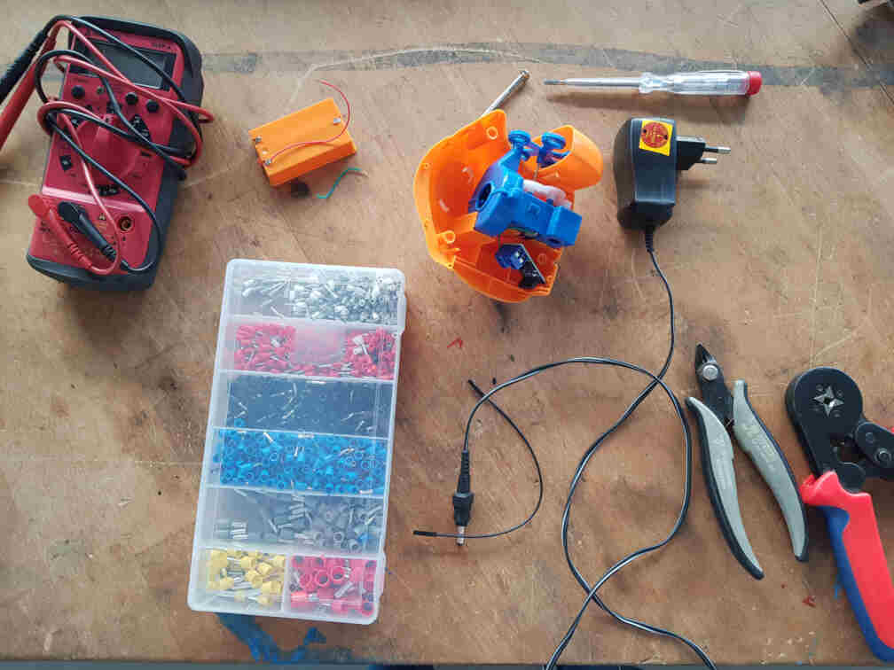

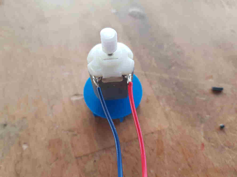
And I replaced the motor wires with more durable ones and connected them to the OUT+/- MOSFET terminals.
The full connection for the bubble receiver side then became as follows:
| Arduino Nano | nRF24L01 | MOSFET |
|---|---|---|
| Pin 3.3V | Pin VCC | - |
| Pin GND | Pin GND | Pin GND |
| Pin 5 | - | Pin TRIG/PWM |
| Pin 7 | Pin CE | - |
| Pin 8 | Pin CSN | - |
| Pin 11 | Pin MOSI | - |
| Pin 12 | Pin MISO | - |
| Pin 13 | Pin SCK | - |
Programming the Microcontroller
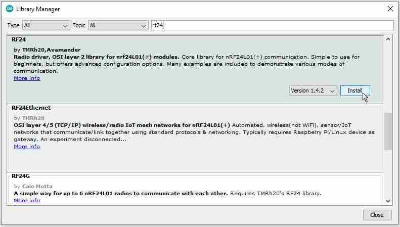
Before I began writing the code part, I had to install the radio transceiver arduino library RF24 by TMRh20 and Avamader.
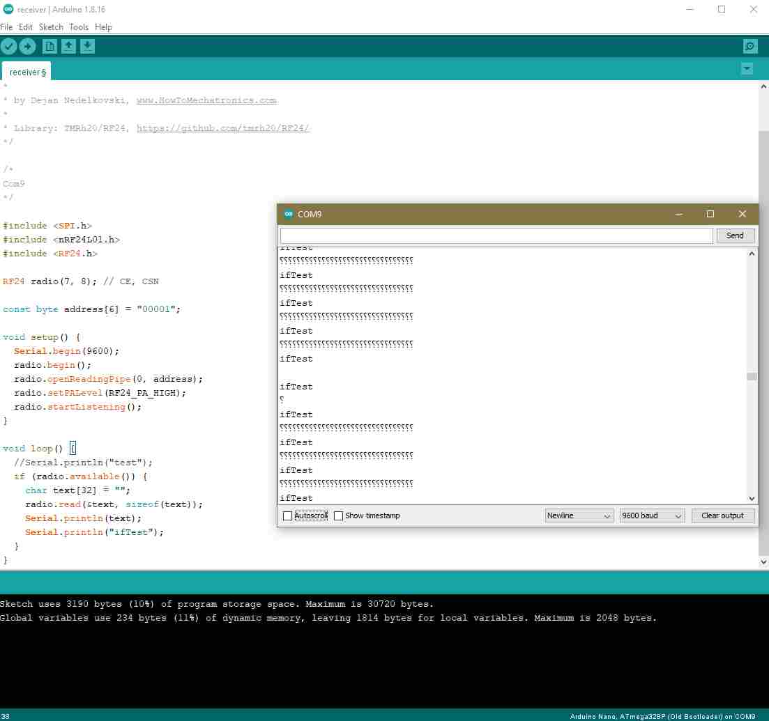
I then connected the second transceiver to the other Arduino Nano board to test the communication codes I got from Dejan Nedelkovski's page. I experimented with the signal strength between RF24_PA_MIN and RF24_PA_HIGH, and added some test lines to the receiver side for debugging with the Serial Monitor.
/*
* Arduino Wireless Communication Tutorial
*     Example 1 - Transmitter Code
*
* by Dejan Nedelkovski, www.HowToMechatronics.com
*
* Library: TMRh20/RF24, https://github.com/tmrh20/RF24/
*/

#include <SPI.h>
#include <nRF24L01.h>
#include <RF24.h>

RF24 radio(7, 8); // CE, CSN

const byte address[6] = "00001";

void setup() {
	radio.begin();
	radio.openWritingPipe(address);
	radio.setPALevel(RF24_PA_MIN);
	radio.stopListening();
}

void loop() {
	const char text[] = "Hello World";
	radio.write(&text, sizeof(text));
	delay(1000);
}
/*
* Arduino Wireless Communication Tutorial
* Example 1 - Receiver Code
*
* by Dejan Nedelkovski, www.HowToMechatronics.com
*
* Library: TMRh20/RF24, https://github.com/tmrh20/RF24/
*/
#include <SPI.h>
#include <nRF24L01.h>
#include <RF24.h>
RF24 radio(7, 8); // CE, CSN
const byte address[6] = "00001";
void setup() {
Serial.begin(9600);
radio.begin();
radio.openReadingPipe(0, address);
radio.setPALevel(RF24_PA_MIN);
radio.startListening();
}
void loop() {
if (radio.available()) {
char text[32] = "";
radio.read(&text, sizeof(text));
Serial.println(text);
}
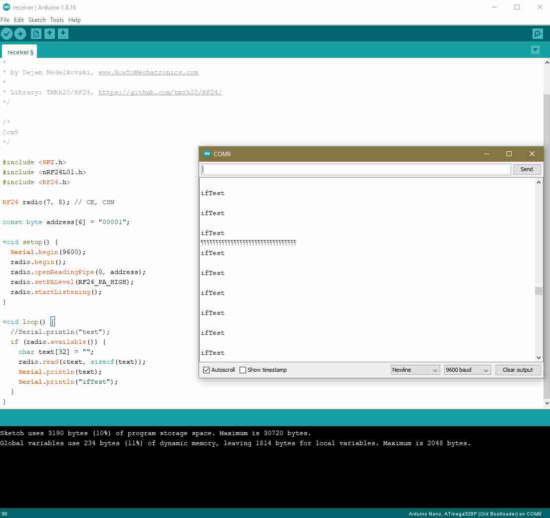
}Although I double and triple checked my code and connections, I was getting no signals or undefined characters (picture on the left). I relocated my setup and tried my code again, and I was getting rather more undefined characters than no signal (picture on the right). I pent even further time trying to figure out what was causing this problem.
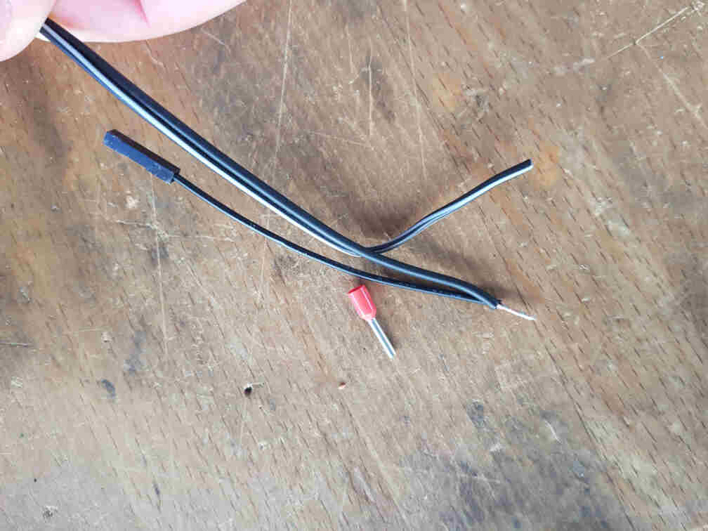
Until I started suspecting the actual connections between the modules, because I could not think of any other reason that would make more sense. So I set up to test the jumper wires with a multimeter.
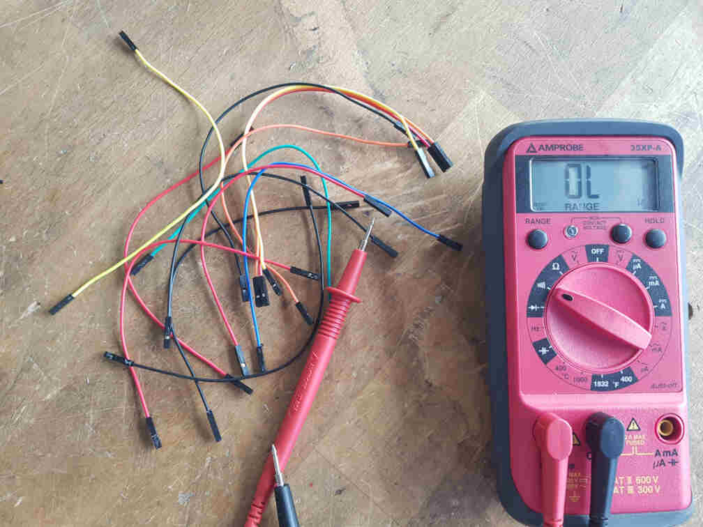
And what do you know, the wires were actually the cause of the problem! So I got all connections some new jumper wires...
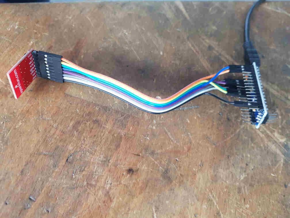
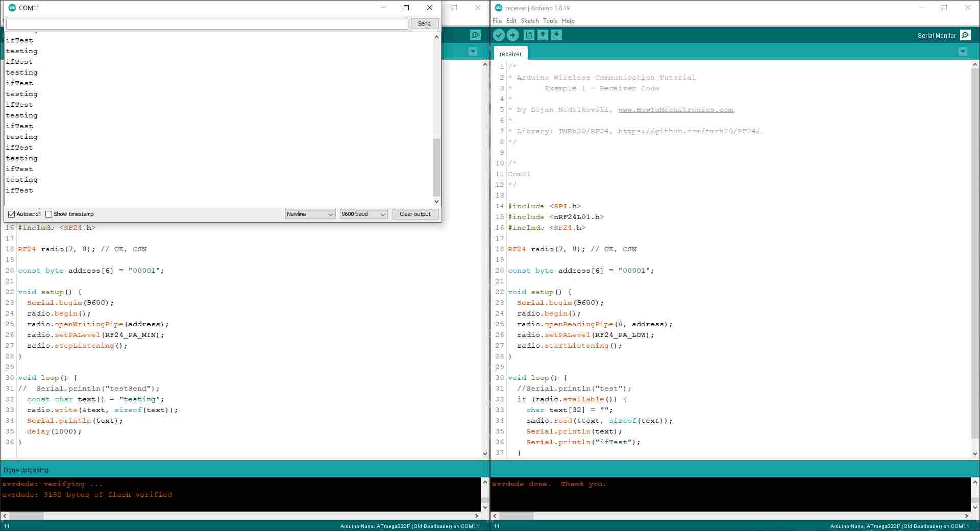
And it worked like a treat! The debugging line I added to make sure that the code was going into the if (radio.available()) statement was showing up on the Serial Monitor.
After that I hooked everything up on the receiver side.
And then I wrote a test code that allows the receiver to control the MOSFET state according to the incoming message from the sender.
After all hardware was working as intended, I put everything together and closed the bubble maker.
Last step was then to adapt the sender code so that is can be integrated into the actuation mechanism on our machine. It is supposed to listen to a high signal on an input pin (connected to an output pin og the mechanism microcontroller) and send the message to the bubble machine receiver to turn on the bubbles.
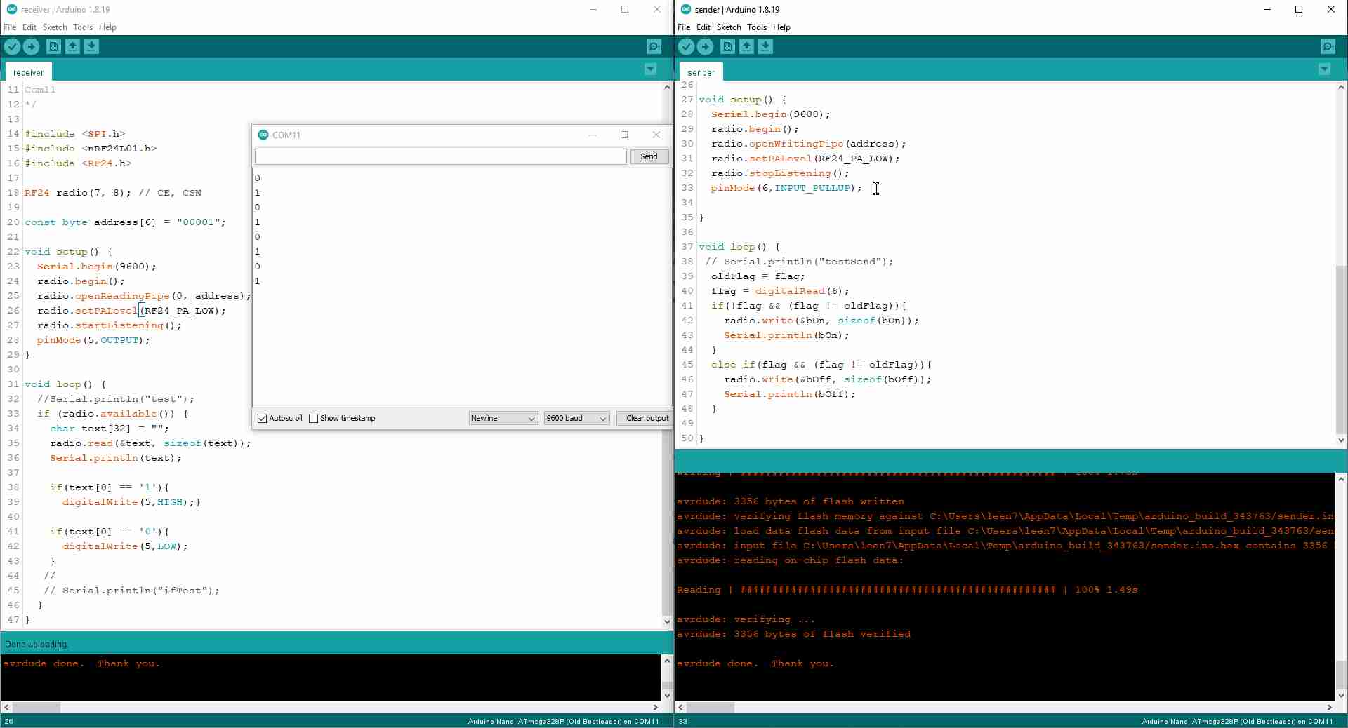
And here is the full code for both microcontrollers, the sender and the receiver.
// Sender

#include <SPI.h>
#include <nRF24L01.h>
#include <RF24.h>

RF24 radio(7, 8); // CE, CSN

const byte address[6] = "00001";

char bOn[] = "1";
char bOff[] = "0";
bool flag = 0;
bool oldFlag = 0;

void setup() {
	Serial.begin(9600);
	radio.begin();
	radio.openWritingPipe(address);
	radio.setPALevel(RF24_PA_LOW);
	radio.stopListening();
	pinMode(6,INPUT_PULLUP);

}

void loop() {
	// Serial.println("testSend");
	oldFlag = flag;
	flag = digitalRead(6);
	if(!flag && (flag != oldFlag)){
	radio.write(&bOn, sizeof(bOn));
	Serial.println(bOn);
	}
	else if(flag && (flag != oldFlag)){
	radio.write(&bOff, sizeof(bOff));
	Serial.println(bOff);
	}
}
// Receiver
#include <SPI.h>
#include <nRF24L01.h>
#include <RF24.h>
RF24 radio(7, 8); // CE, CSN
const byte address[6] = "00001";
void setup() {
Serial.begin(9600);
radio.begin();
radio.openReadingPipe(0, address);
radio.setPALevel(RF24_PA_LOW);
radio.startListening();
pinMode(5,OUTPUT);
}
void loop() {
//Serial.println("test");
if (radio.available()) {
char text[32] = "";
radio.read(&text, sizeof(text));
Serial.println(text);
if(text[0] == '1'){
digitalWrite(5,HIGH);}
if(text[0] == '0'){
digitalWrite(5,LOW);
}
//
// Serial.println("ifTest");
}
}