Leen Nijim
Final Project
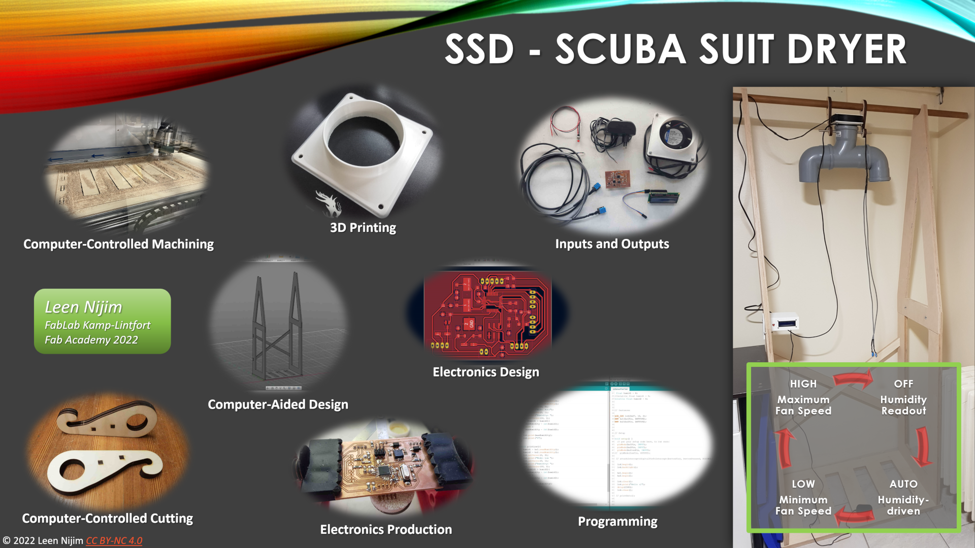
SSD - Scuba Suit Dryer
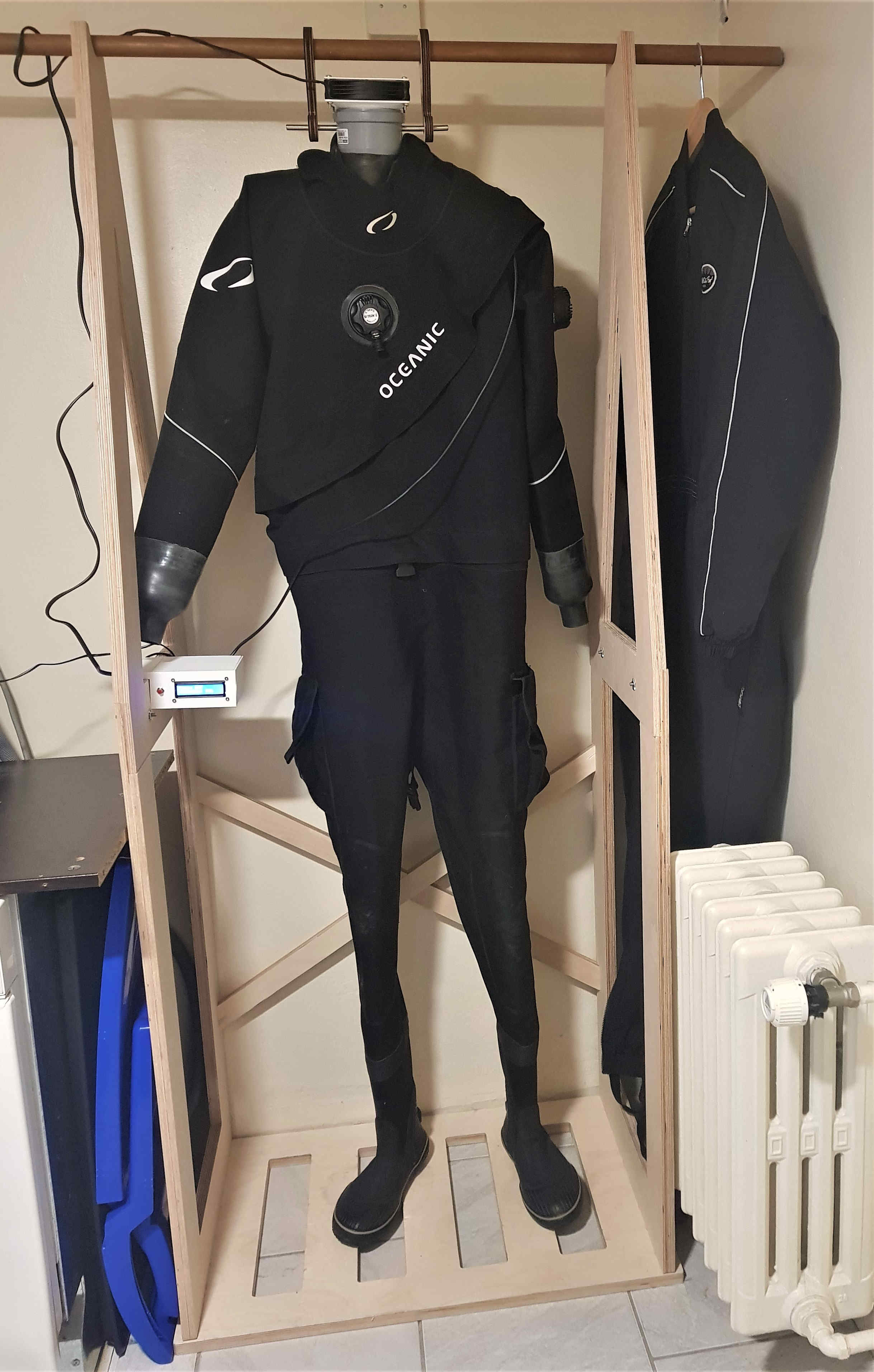
Hero Shots
Downloads
Computer-Controlled Machining
Electronics Design and Production
3D Printing
Computer-Controlled Cutting
Programming
How it All Started
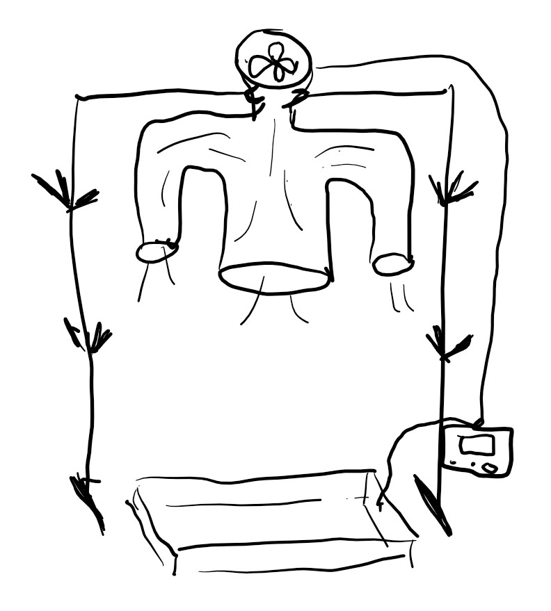
For my final project, I’d like to make an active scuba dive suit drying system. Ideally, I’d like the hanging rack to be modular so I can install it and use it in whichever accommodation I happen to be staying at. But at the same time it also has to be structurally sturdy enough to not collapse under continuous loading as it will act as a permanent hanging storage space for my scuba suit. Other features I’d like my system to have are:
- Soft contours to support the scuba suit without damaging it.
- Ventilation ducts with an electric fan.
- Humidity sensors to be inserted into the drying suit.
- An interface - maybe an LCD and some buttons and dials - to allow me to choose which drying program I’d like to use.
- Maybe also some sort of a drainage system to redirect dripping water into a place safe for it to flow to.
Here is a hand-drawn sketch of my idea:
To have my ideas better organized, I've tried to fit my building plan into the weekly topics of my Fab Academy training.
| Topic | Feature Description |
|---|---|
| Computer-Aided Design | 3D model and render all/part of the system |
| Computer-Controlled Cutting | Vinyl cut stickers and markers for the frame |
| Electronics Production | Make a programmer to program my system microcontroller with |
| 3D Scanning and Printing | 3D print parts like fan, hangers, joints, housings |
| Electronics Design | Design and make the microcontroller board |
| Computer-Controlled Machining | Make the hanging rack |
| Embedded Programming | Program the microcontroller board |
| Molding and Casting | ?? |
| Output Devices | Connect LCD and fan motor to the microcontroller |
| Mechanical and Machine Design | ?? |
| Input Devices | Connect humidity sensors, dials and buttons to the microcontroller |
| Networking and Communications | ?? |
| Interface and Application Programming | ?? |
| Last updated on 04.04.2022 |
How it All Happened
Timeline
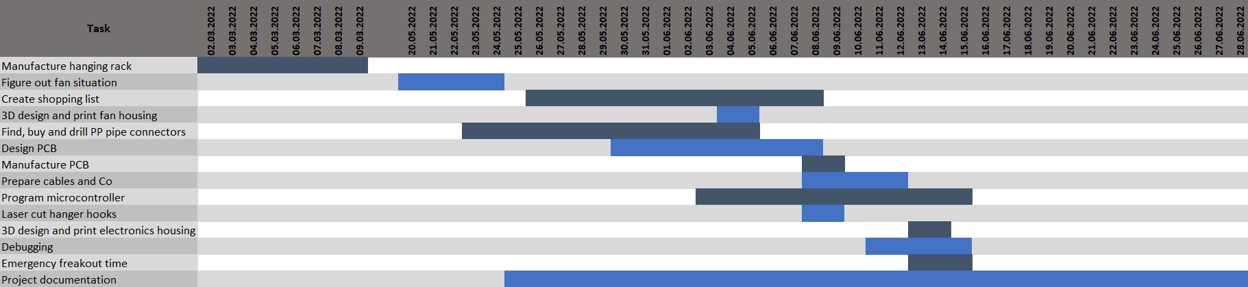
I must admit that I am a pretty good procrastinator. Although I enjoy everything I do, especially during these past 20+ weeks, I was really good at pushing the start dates of any task to the maximum limit. Having weekly deadlines was heaven-sent, though, because I would not have accomplished what I did otherwise. For my final project, it was not much different. I did not properly start working on it until we had no other assignments I could busy myself with. Assignment 17 (see below) helped me get over my need-to-start inertia and got me mentally properly going. In the end, I was able to deliver everything required in time, and I am proud of the quality I have delivered, but I could not have done so without triage and multitasking. I learned how to better allocate available time to each task, learned when to give up and how to do it smartly, and was constantly working on things in parallel. "Document as you go" is something I still need to get better at, though, and I've learned to love it and appreciate the need for details. I've had to go back and forth in my assignments documentation so many times, that I was very thankful to have had to document every last detail. It has become a reflex of mine to document things now, and I need to get better at doing it more efficiently as I go.
Planing
In my Assignment 17 documentation, I discussed the core questions my project should answer. These questions are:
- What will it do?
- Who's done what beforehand?
- What will I design?
- What materials and components will be used?
- Where will they come from?
- How much will they cost?
- What parts and systems will be made?
- What processes will be used?
- What questions need to be answered?
- How will it be evaluated?
And in the end this is how my table of system features looked like:
| Topic | Feature Description |
|---|---|
| Computer-Aided Design | 3D model part of the system |
| Computer-Controlled Cutting | Laser cut hangers for the suit |
| Electronics Design | Design my system microcontroller board |
| Electronics Production | Make the microcontroller board |
| 3D Printing | 3D print fan holder and electronics housing |
| Computer-Controlled Machining | Make the hanging rack |
| Embedded Programming | Program the microcontroller board |
| Output Devices | Connect LCD and fan motor to the microcontroller |
| Input Devices | Connect humidity sensors and button to the microcontroller |
| Networking and Communications | Communicate with the LCD via I2C |
Computer-Aided Design & Computer-Controlled Machining
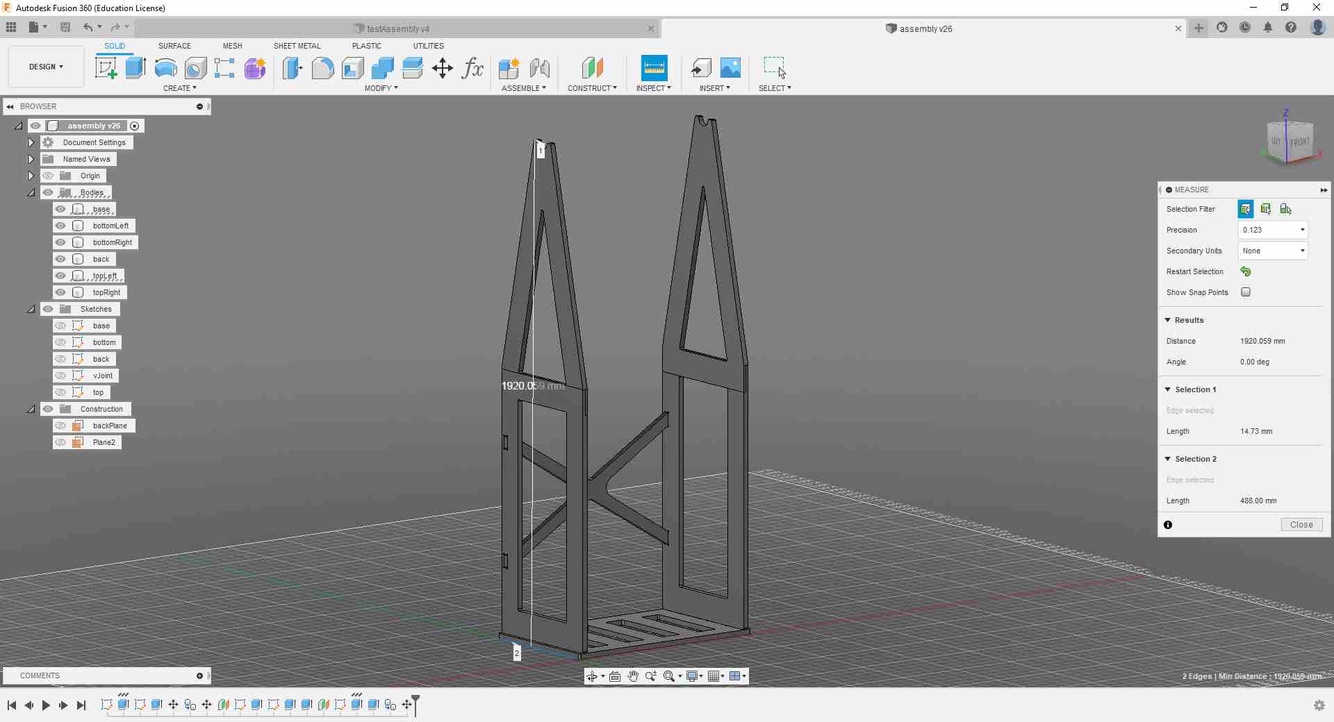
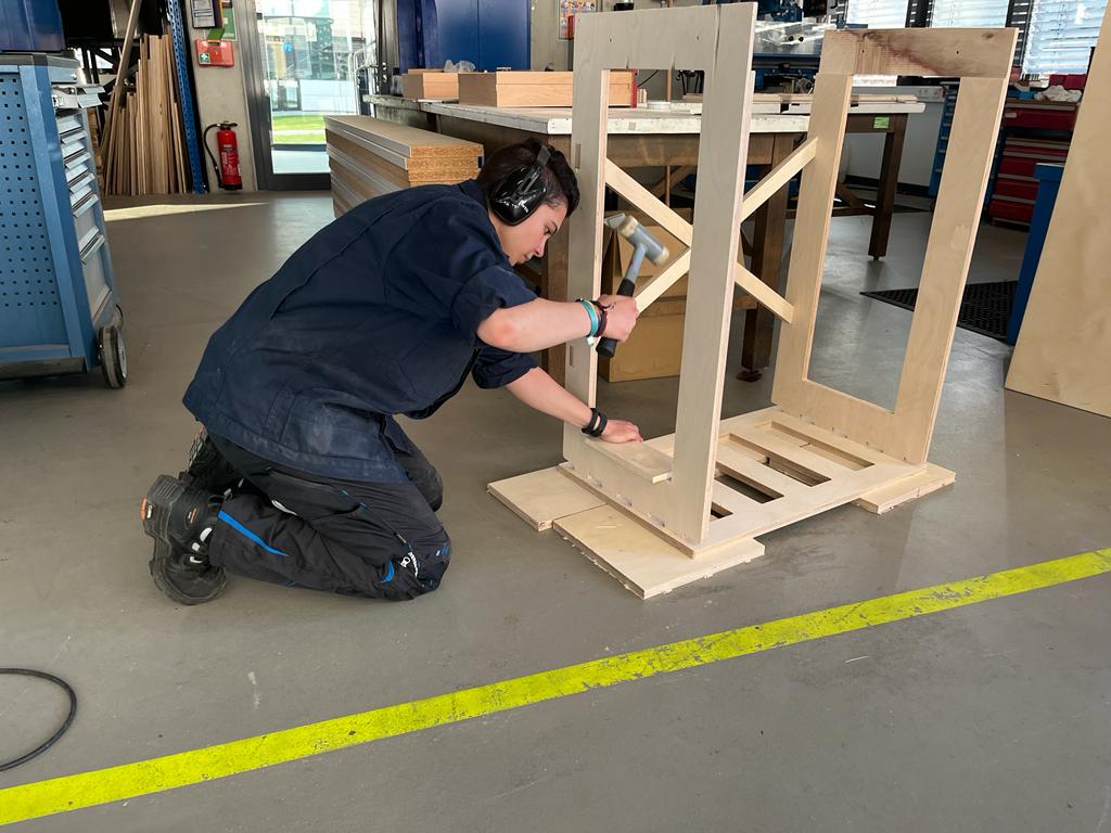
The first part of my project was planned and manufactured during Assignment 8, where I made the hanging rack for the scuba suit.
I did the 3D design using Fusion 360.
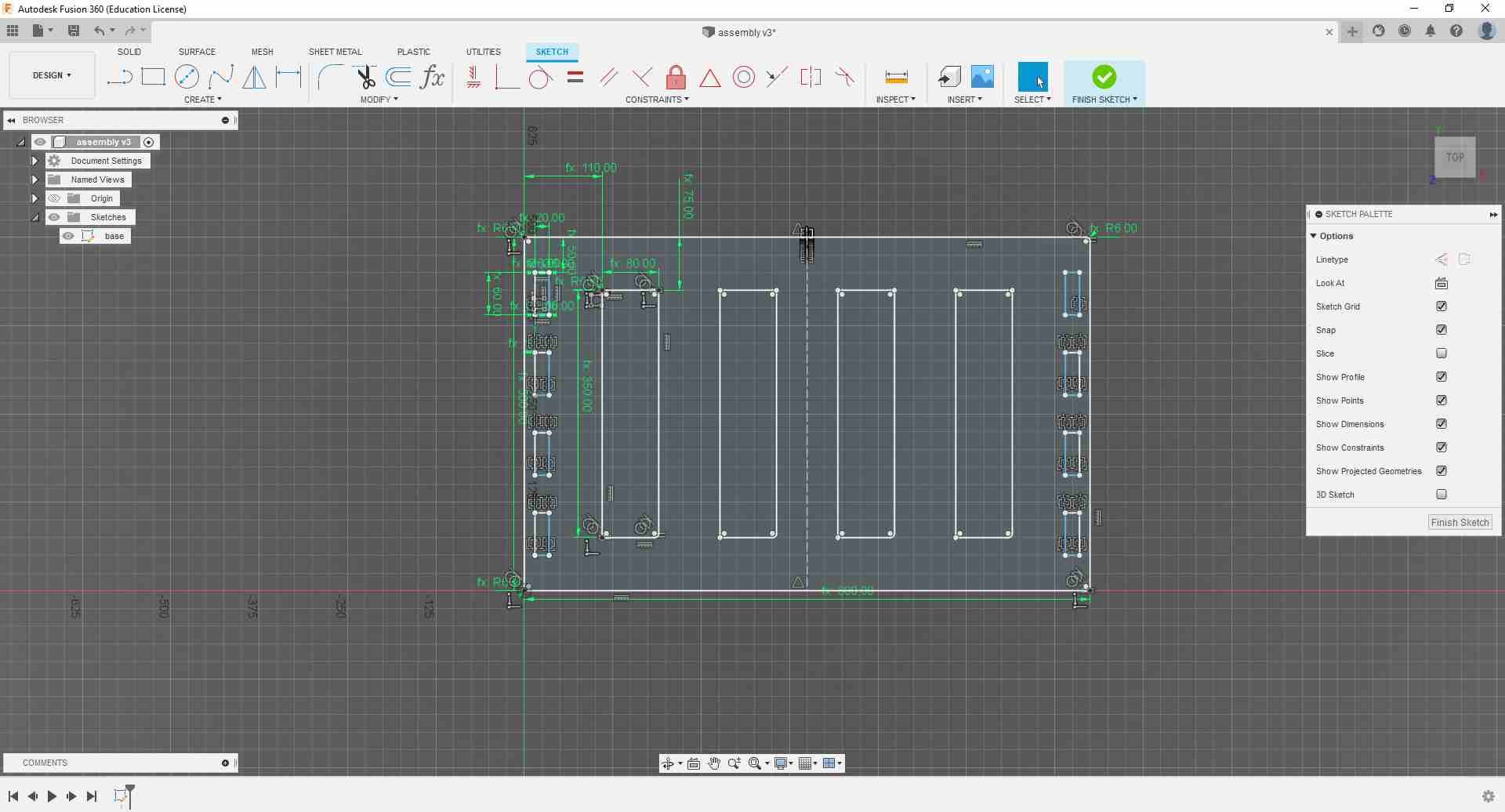
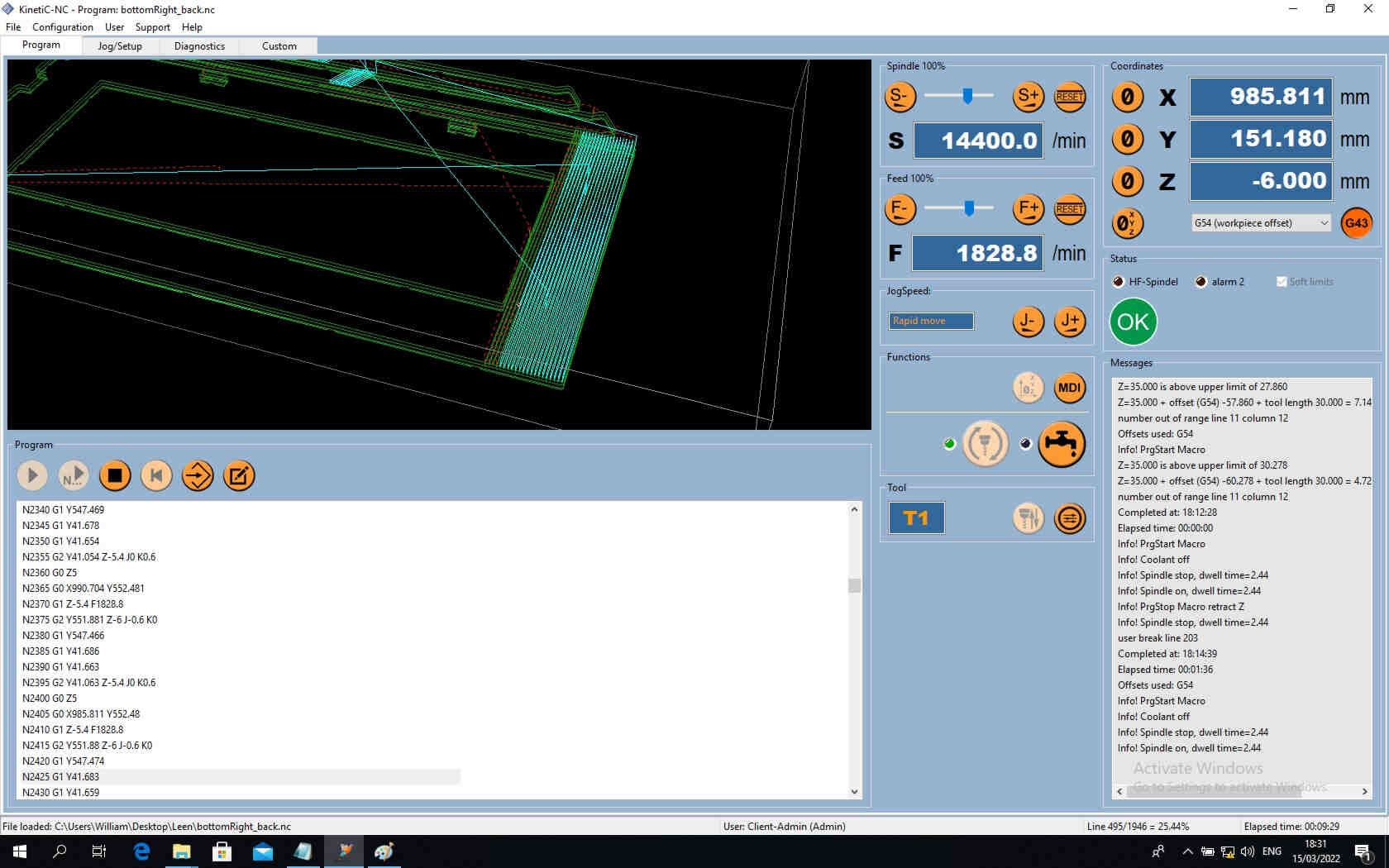
And prepared the CAM in there as well.
.jpg)
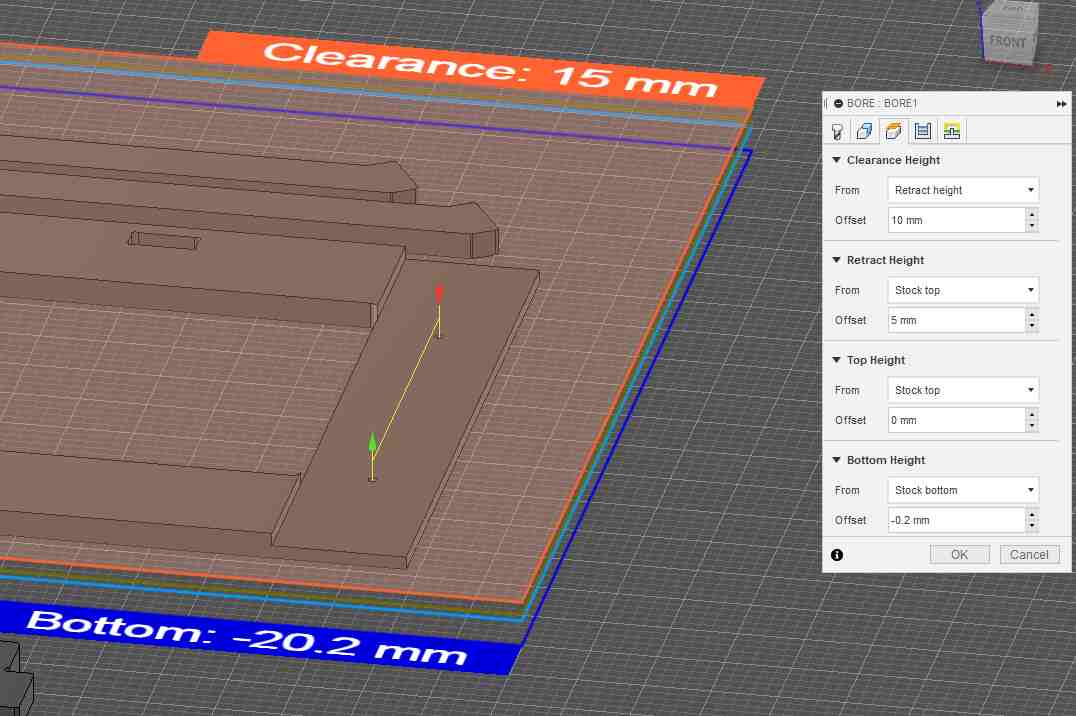
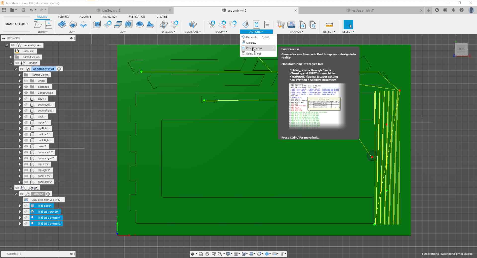
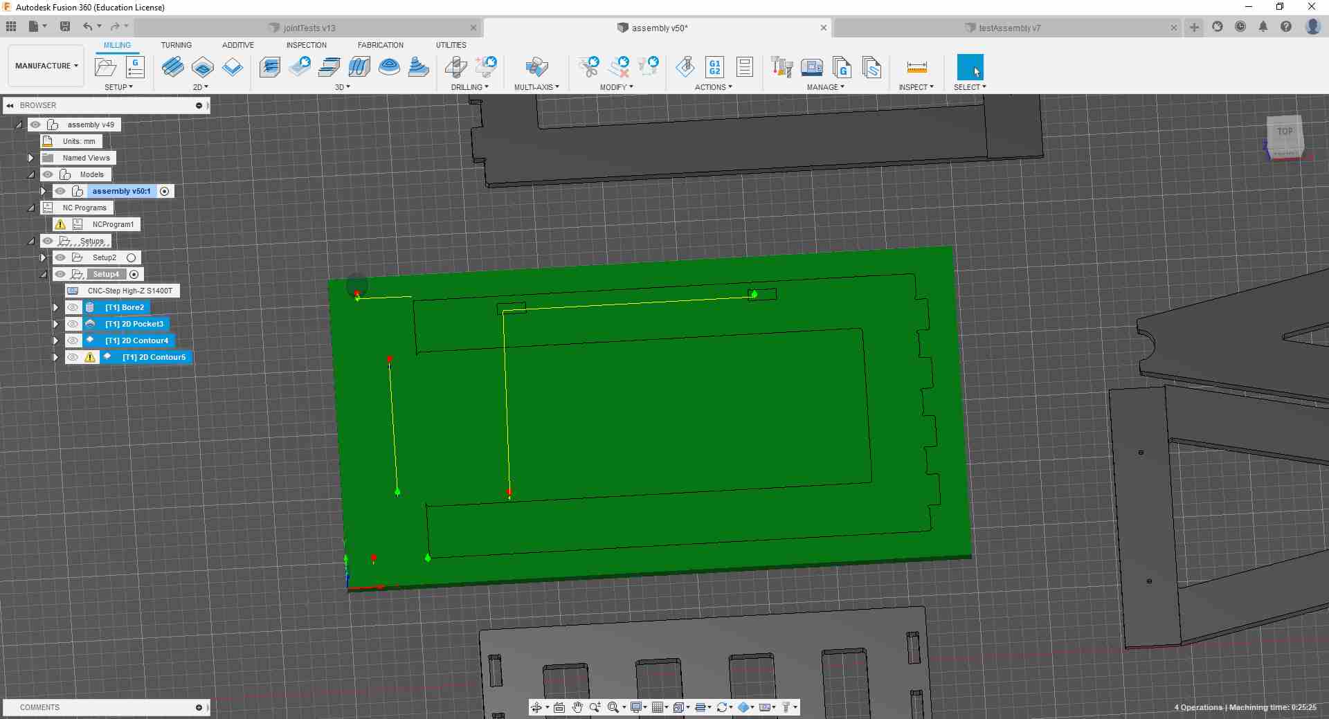
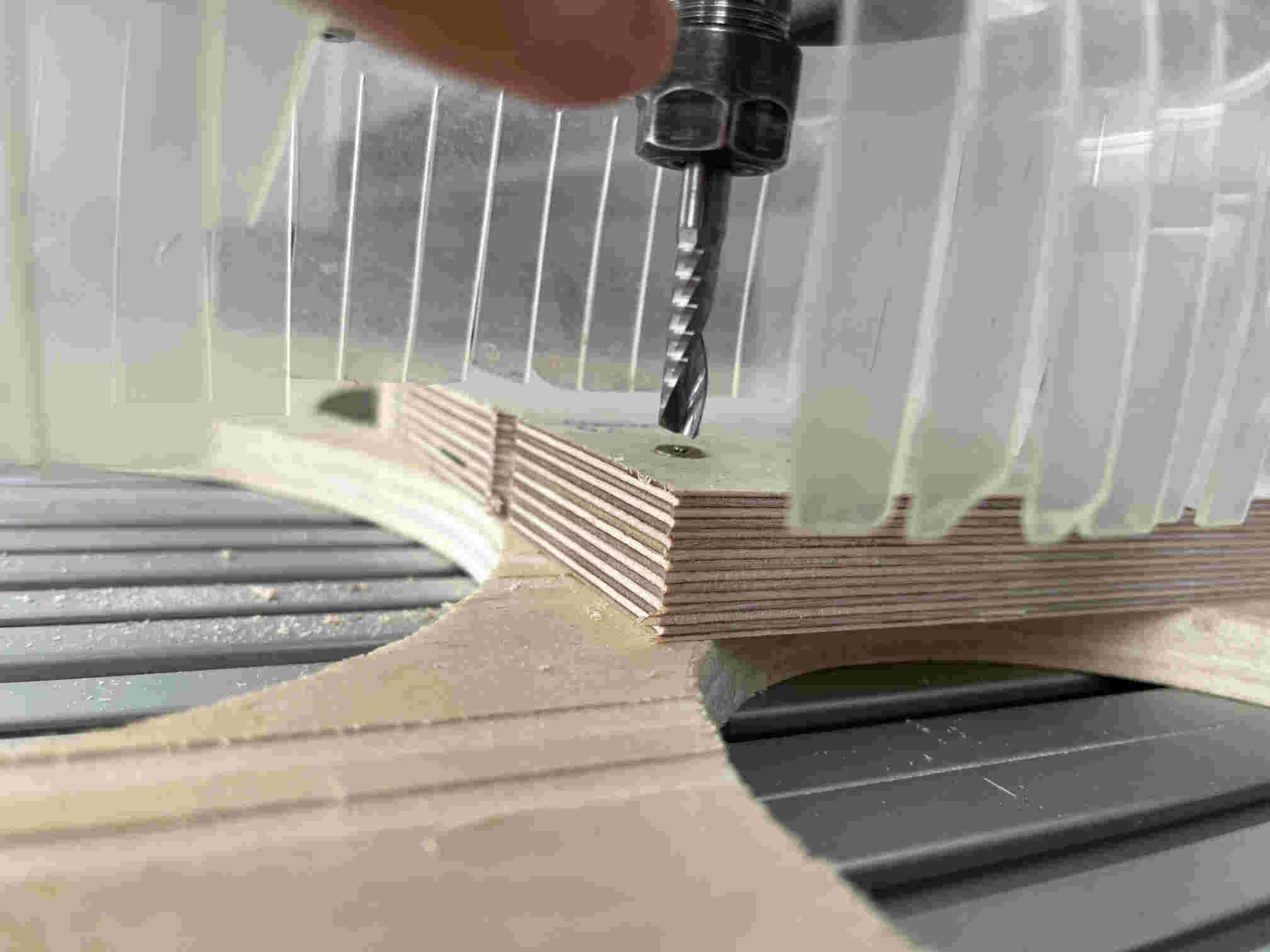
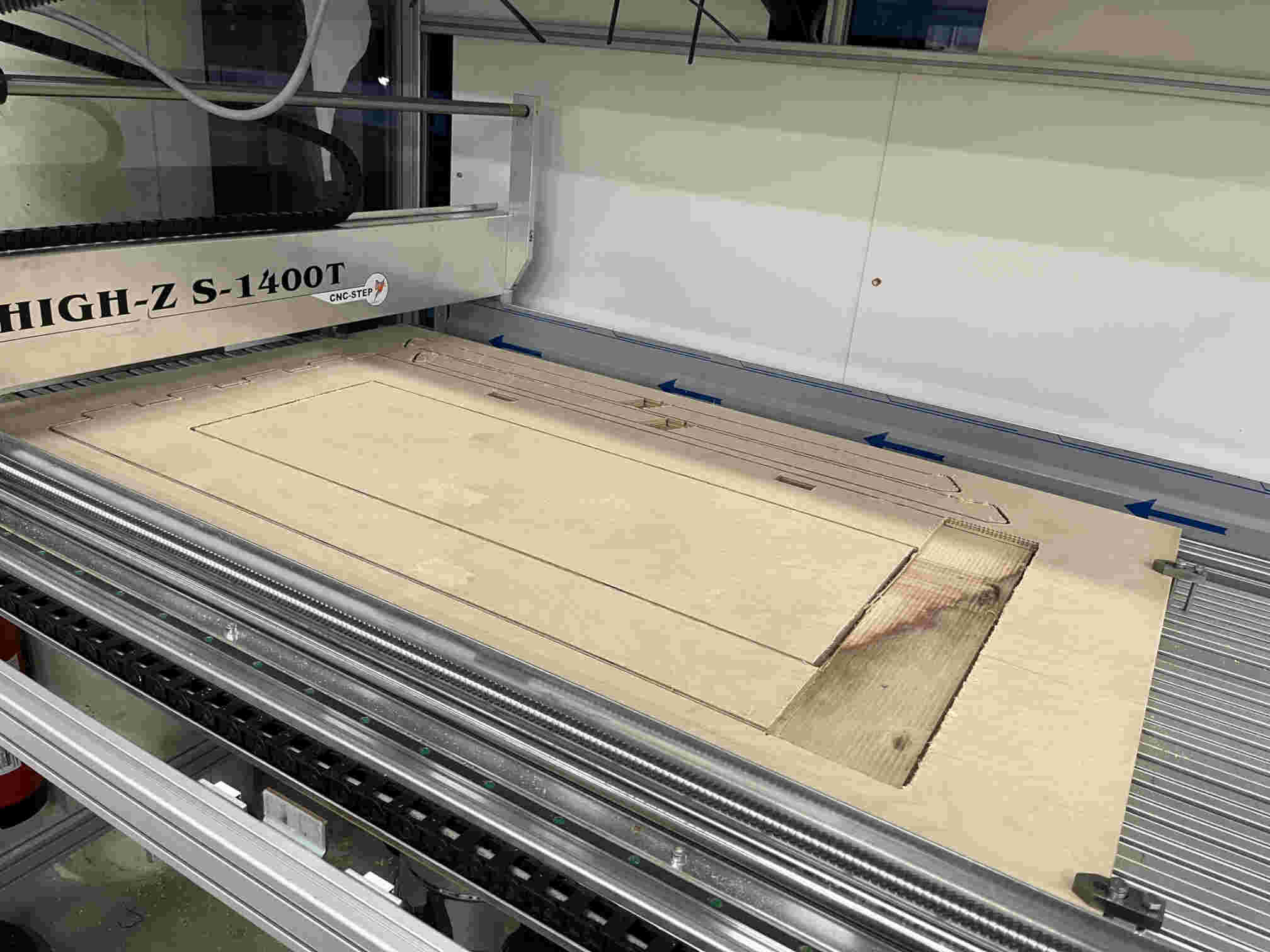
Then manufactured it on our CNC.
Thinking out of the Box
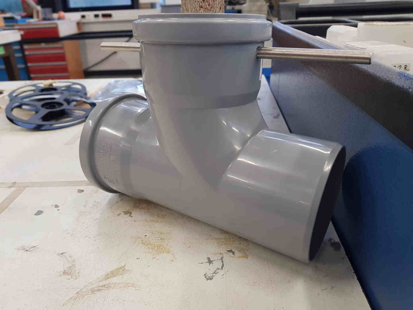
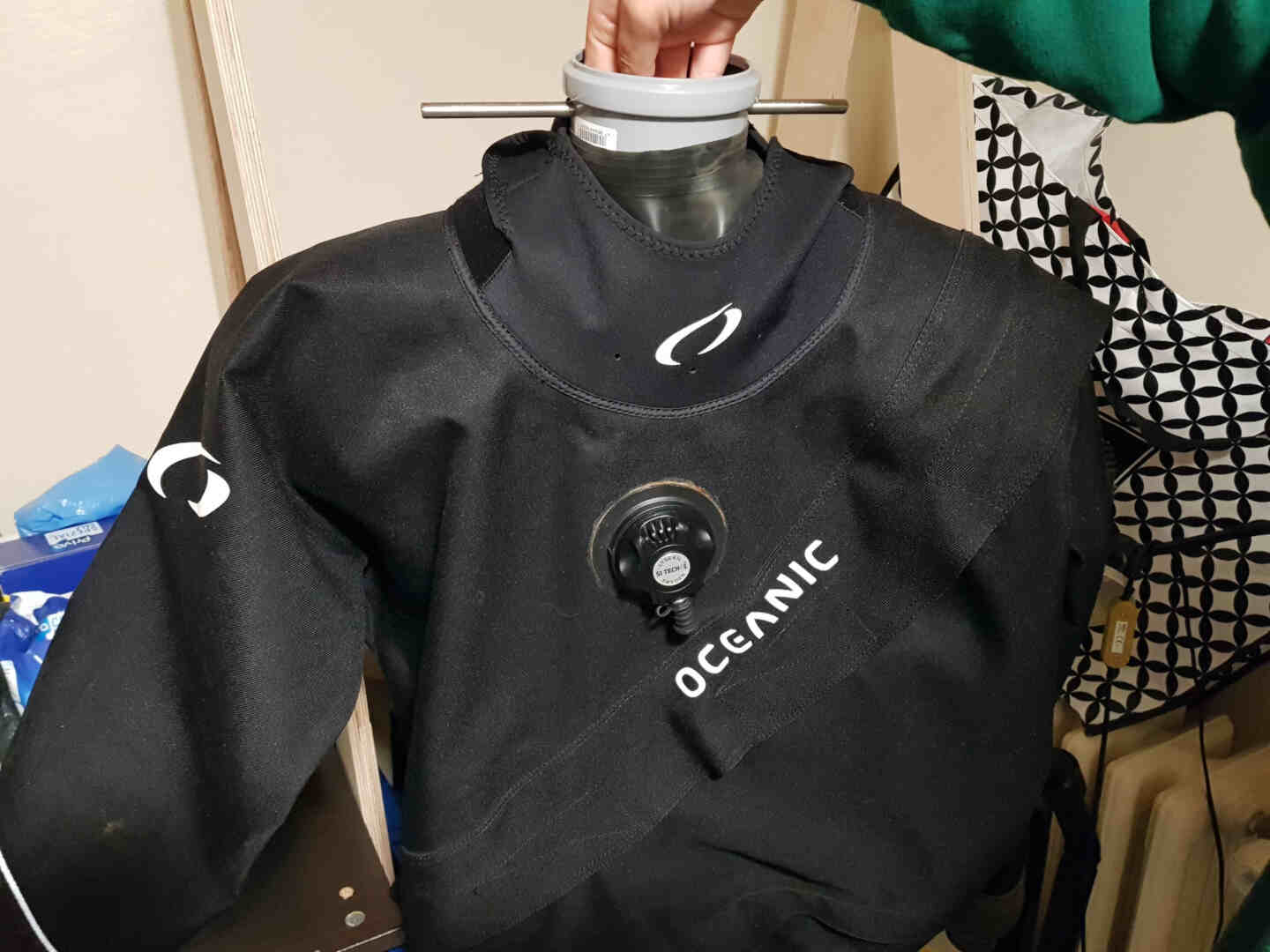
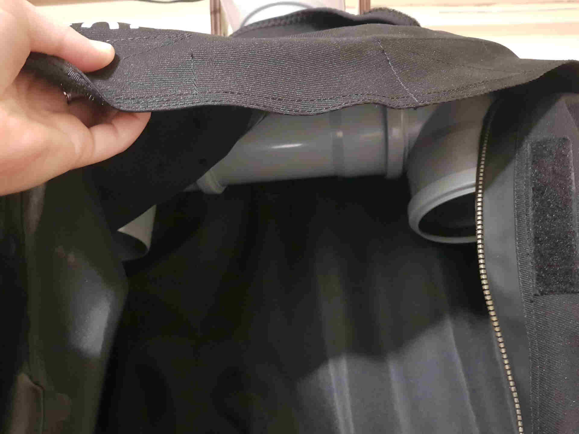
My second mission was to figure out how to best make the hanger part that would:
- Hold my suit up.
- Have smooth surface, so as not to create damage on the long-run.
- Be modular, because it needs to go into the suit from the zipper area and then up through the neck seal.
- Act as an air duct.
- Withstand the continuous load of the suit.
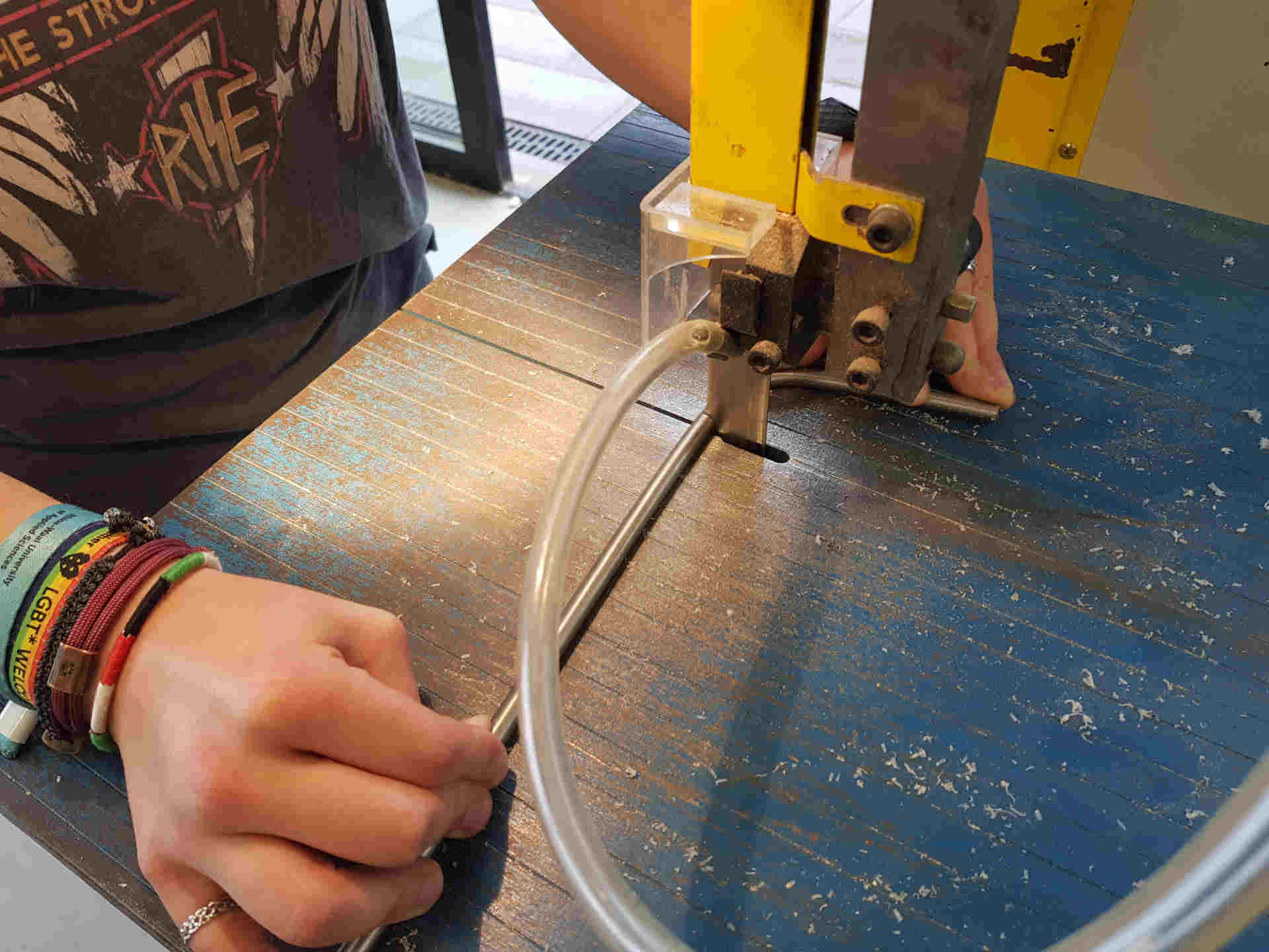
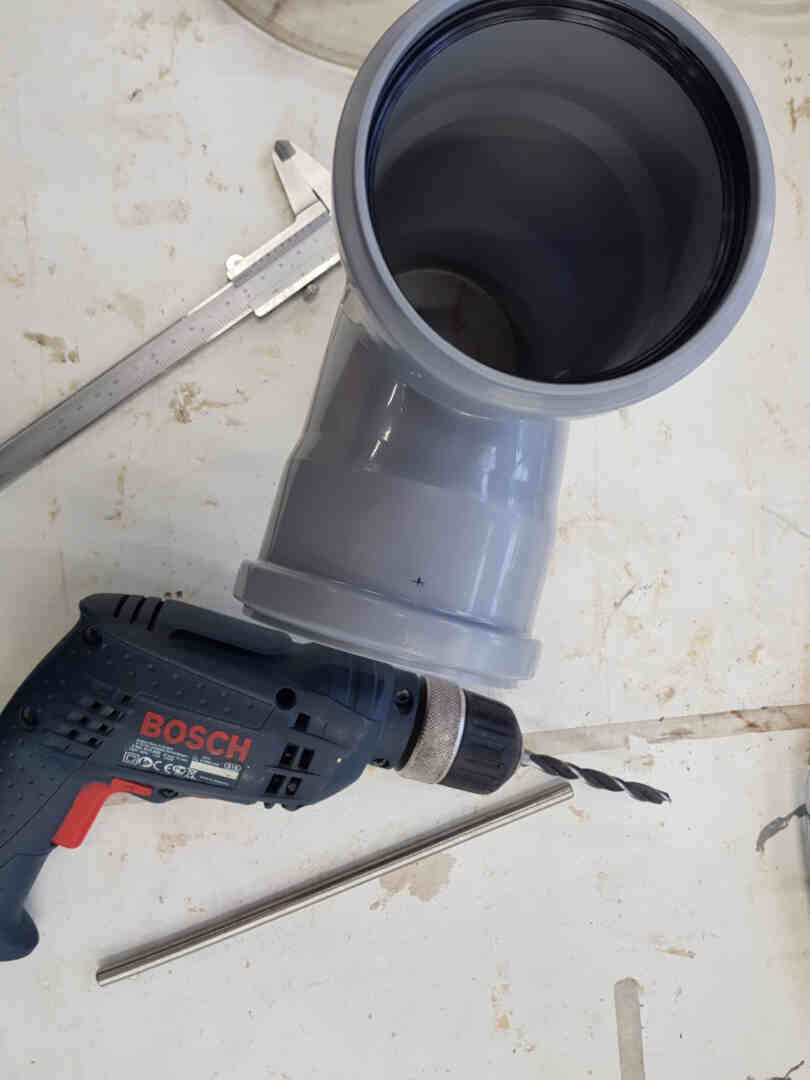
The solution was to buy one T-shaped and two 87° PP pipe connectors, and find a stainless steel piece of rod from our metal scrap. I did the former, and cut the latter into a 230 mm long and 8 mm thick rod.
Inputs and Outputs
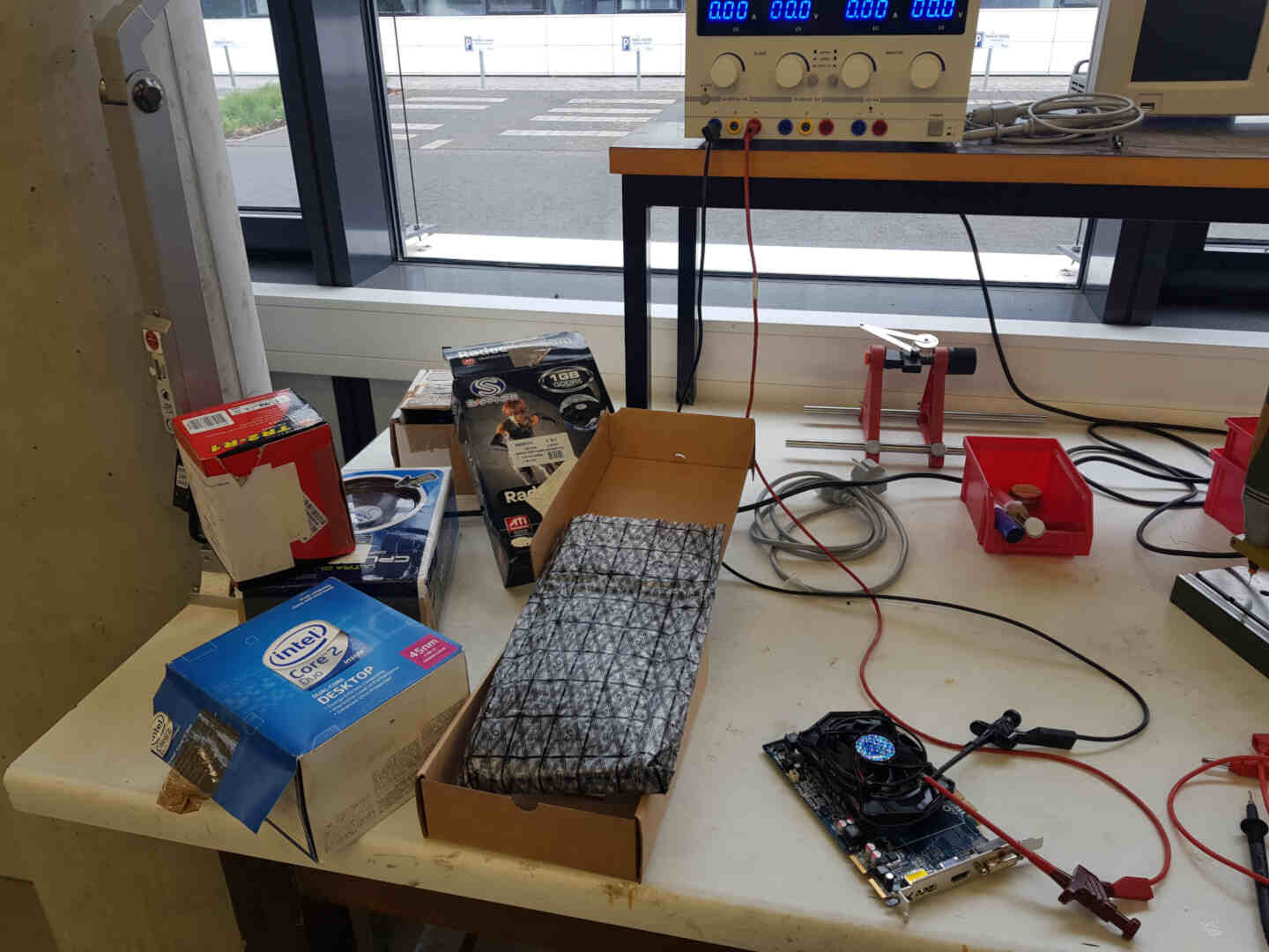
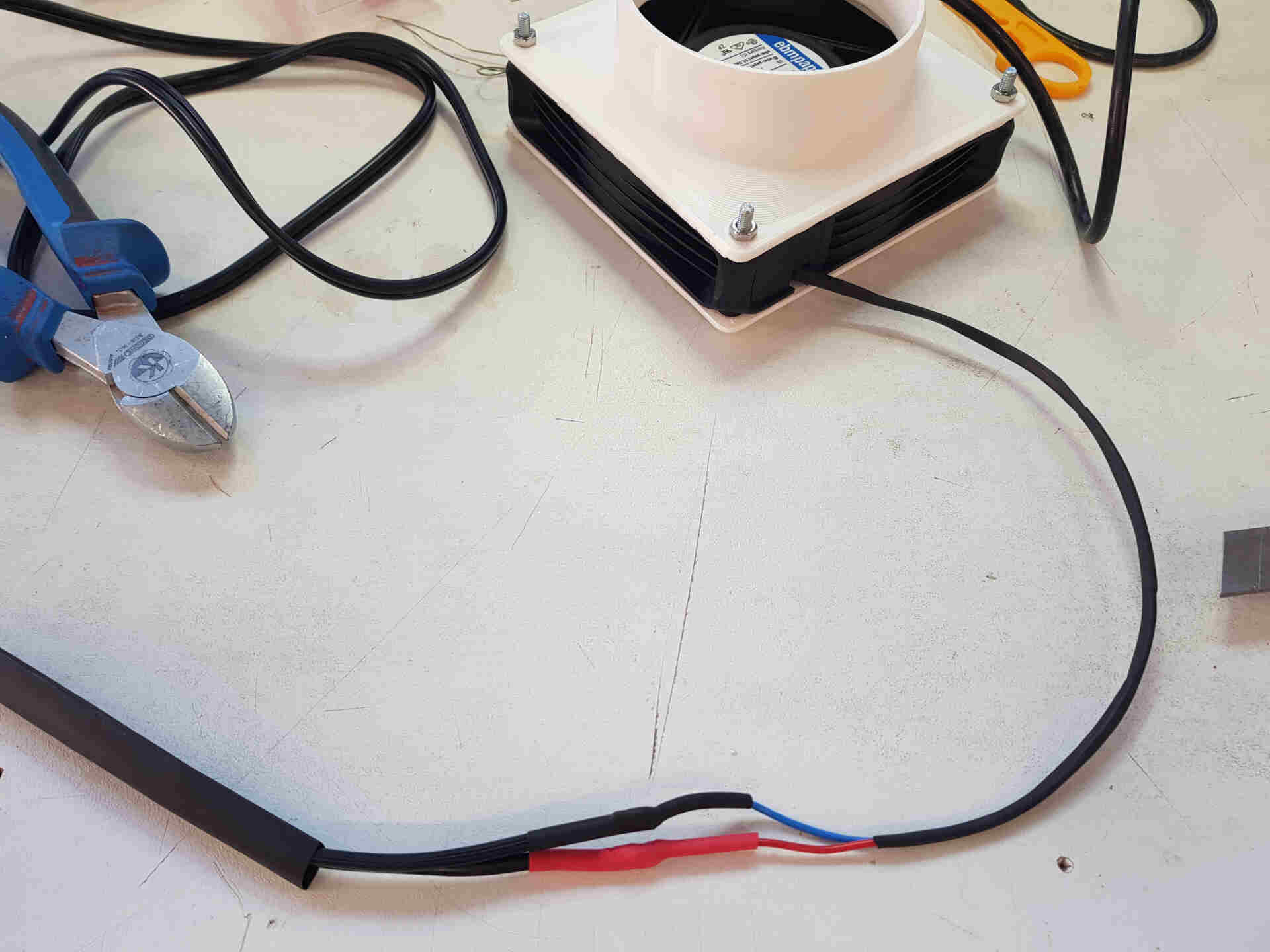
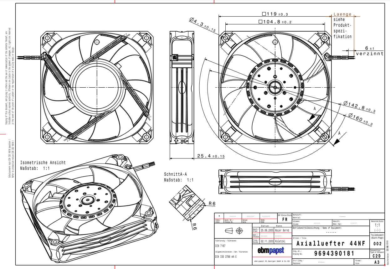
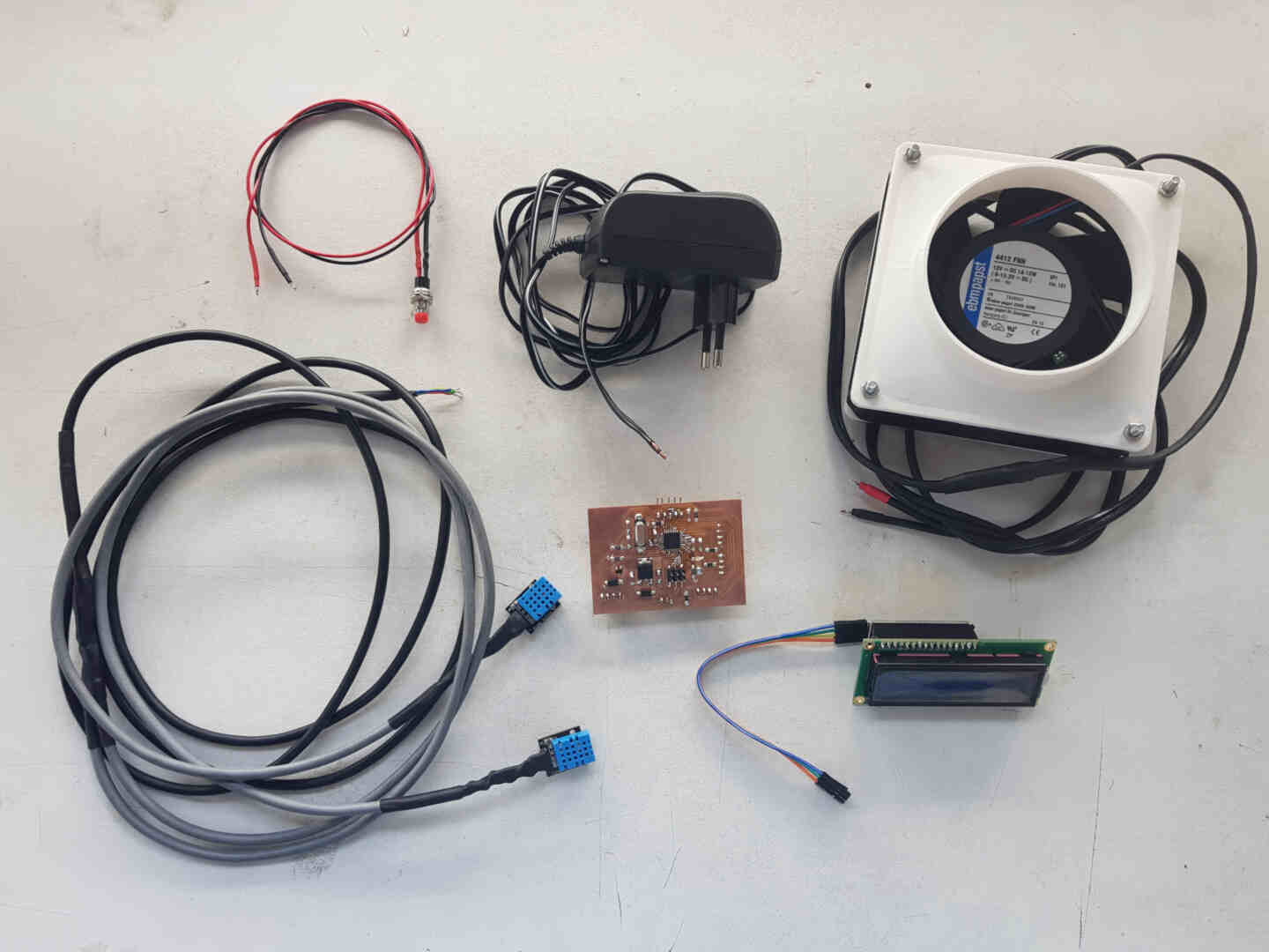
After that I located the lab's fine collection of maybe-functional old computer (and non-computer) fans, and set out to test them and see if I could salvage anything for my project. The winner was this one.
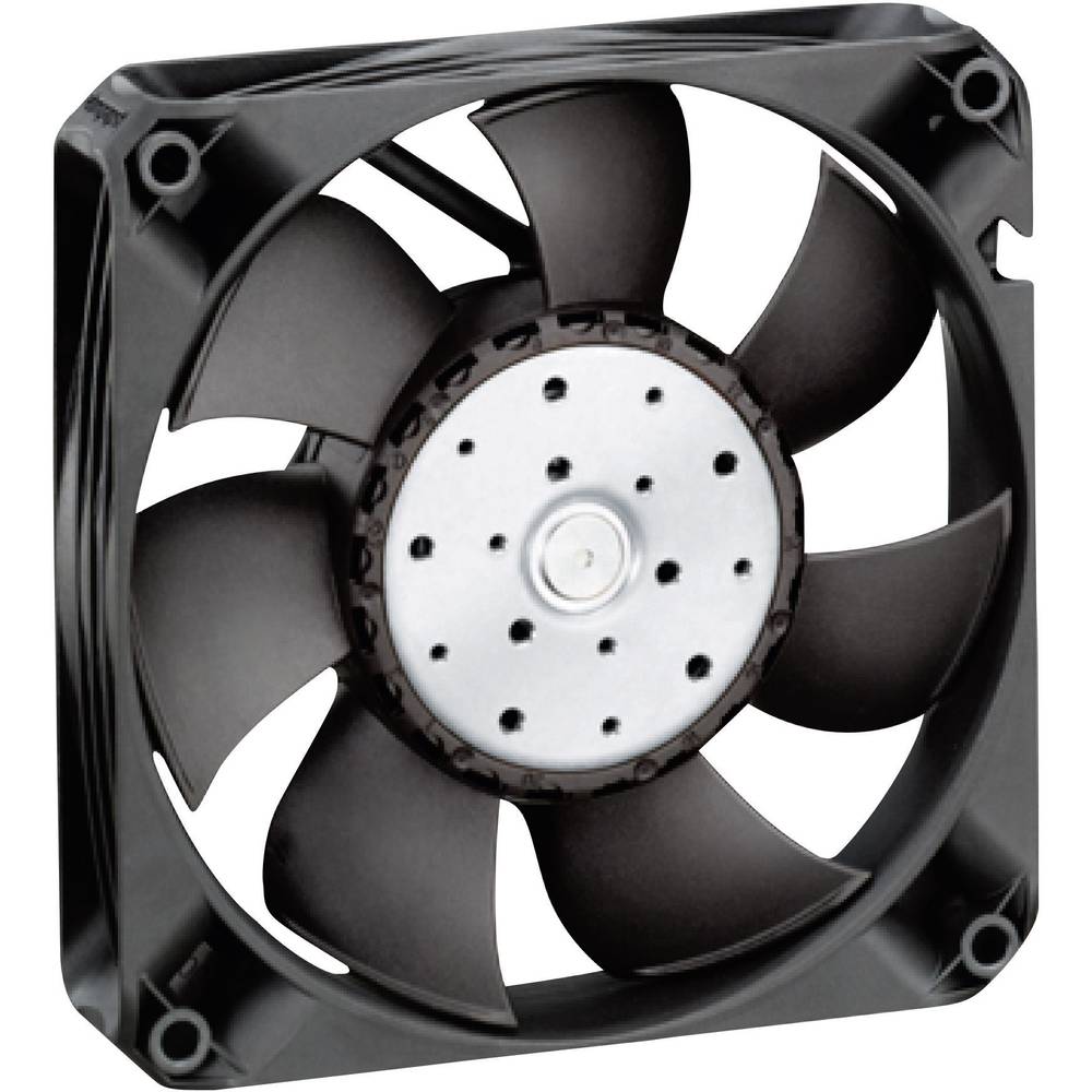 EBM Papst 4412 FNH Axial Fan 12 V/DC
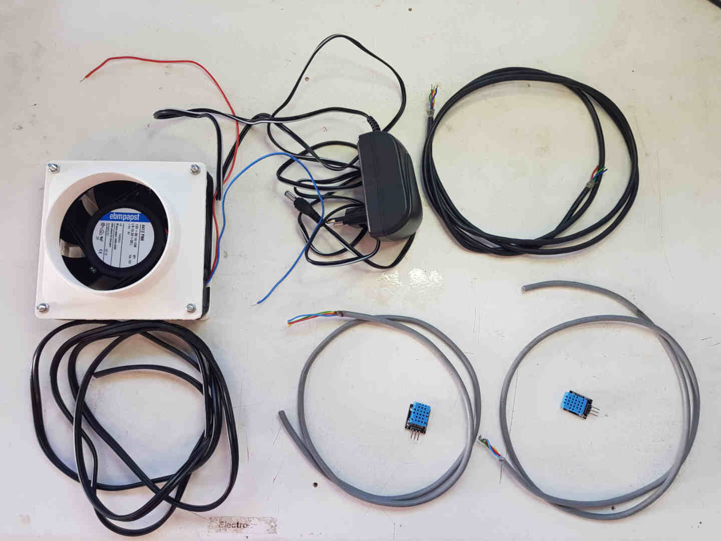
Then I went online to double-check the cable thickness I need for my connections according to the rating of the fan motor.

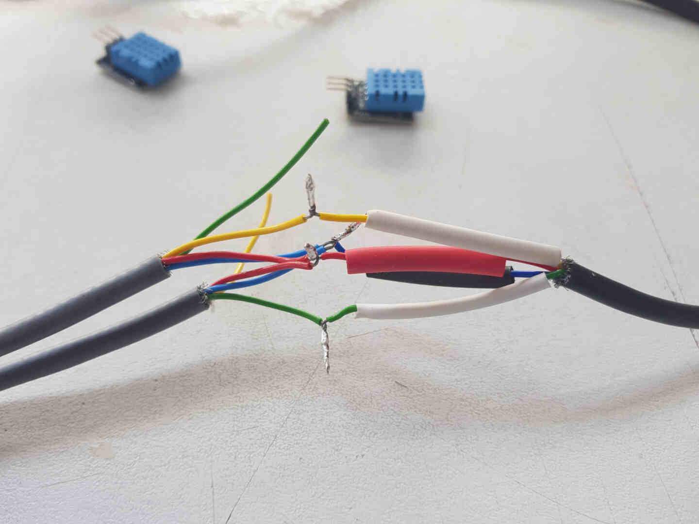
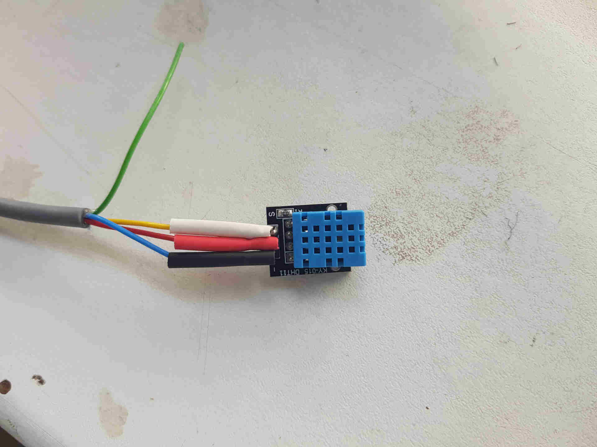
Then found the appropriate cables from our lab's scrap cable cabinet, ordered one DC adapter and two DHT11 sensor modules, and took one of the lab's I2C LCD modules.
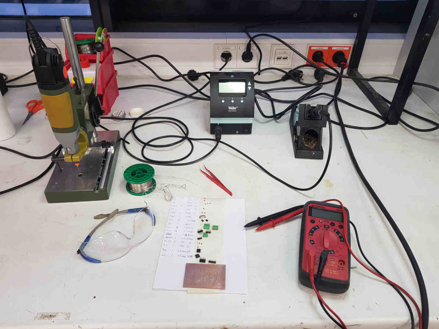
Electronics Design and Production
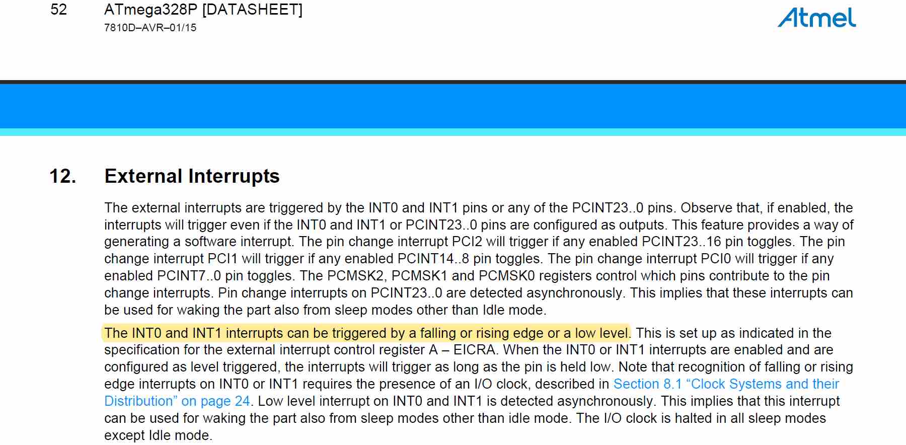
For my system microcontroller, I chose to go with one of the lab's ATmega328P chips. So I first looked through the datasheet for the pinout and made sure that I use the correct pin for connecting the button that will switch the fan modes.
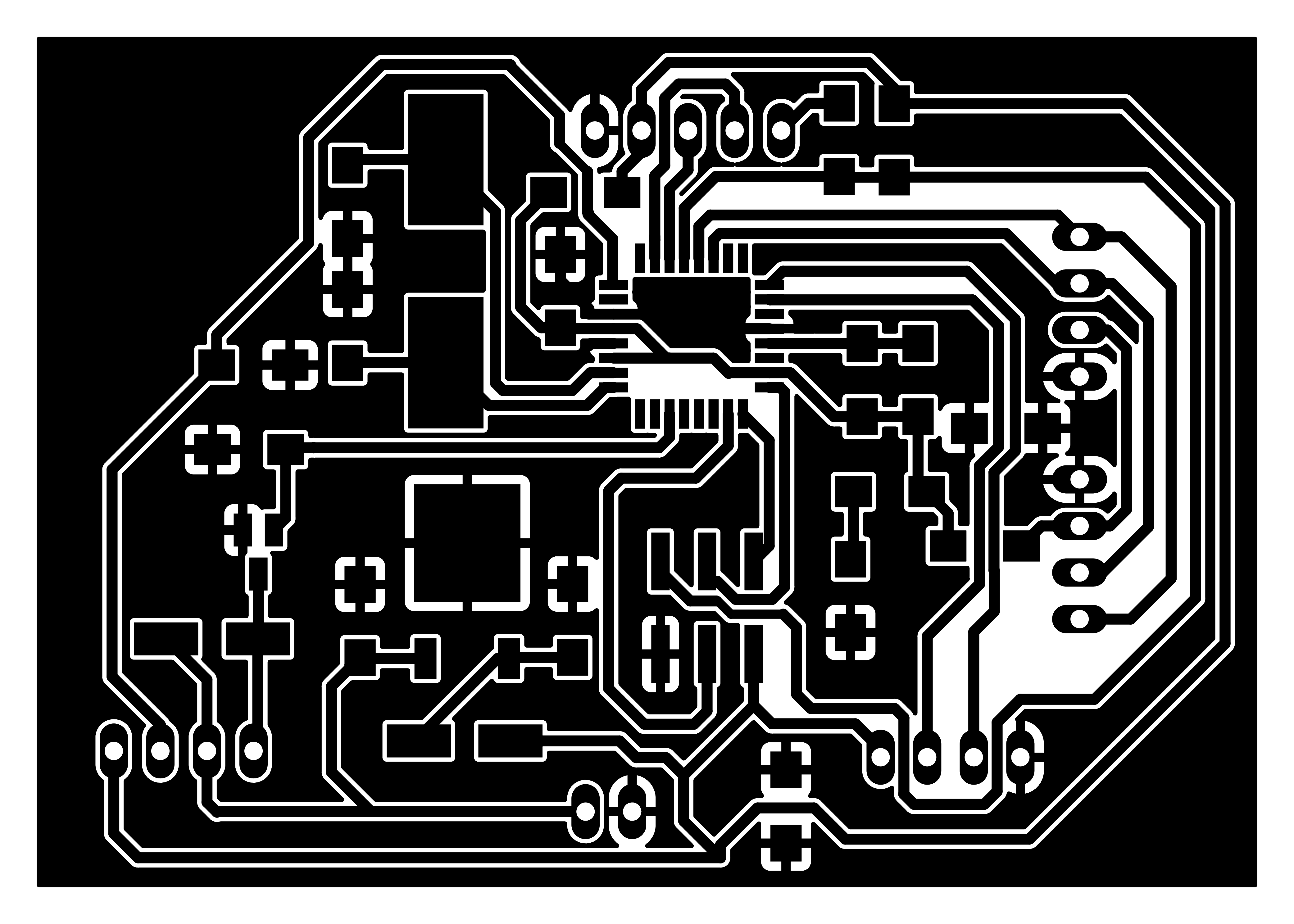
Then I designed the circuitry in KiCad.
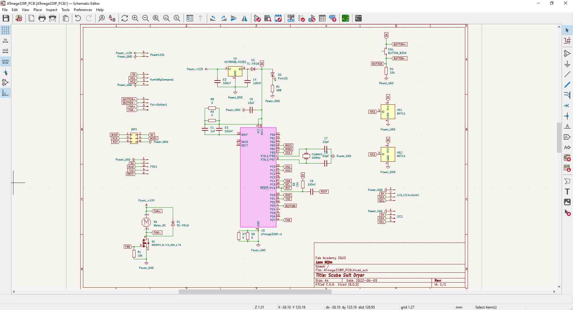
And before I did the routing, I used this online trace width calculator to see what width I should use for the fan motor connections.
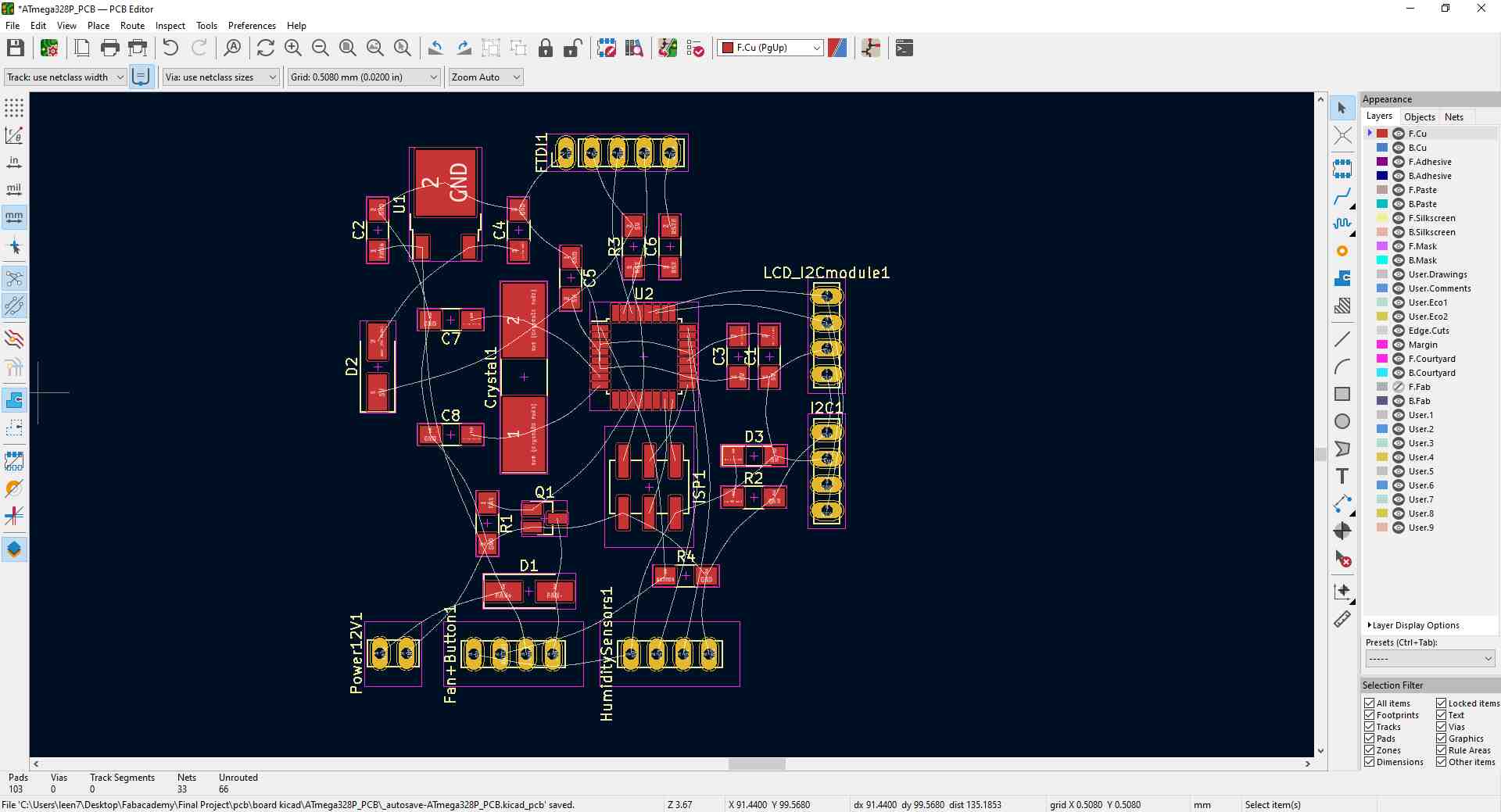

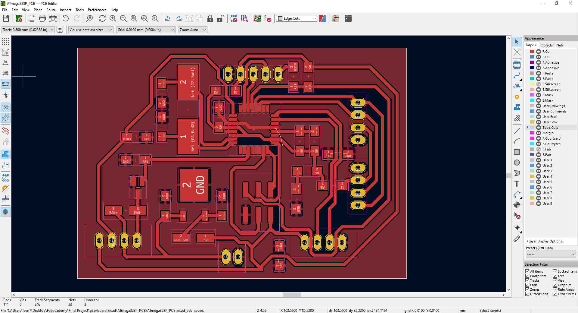
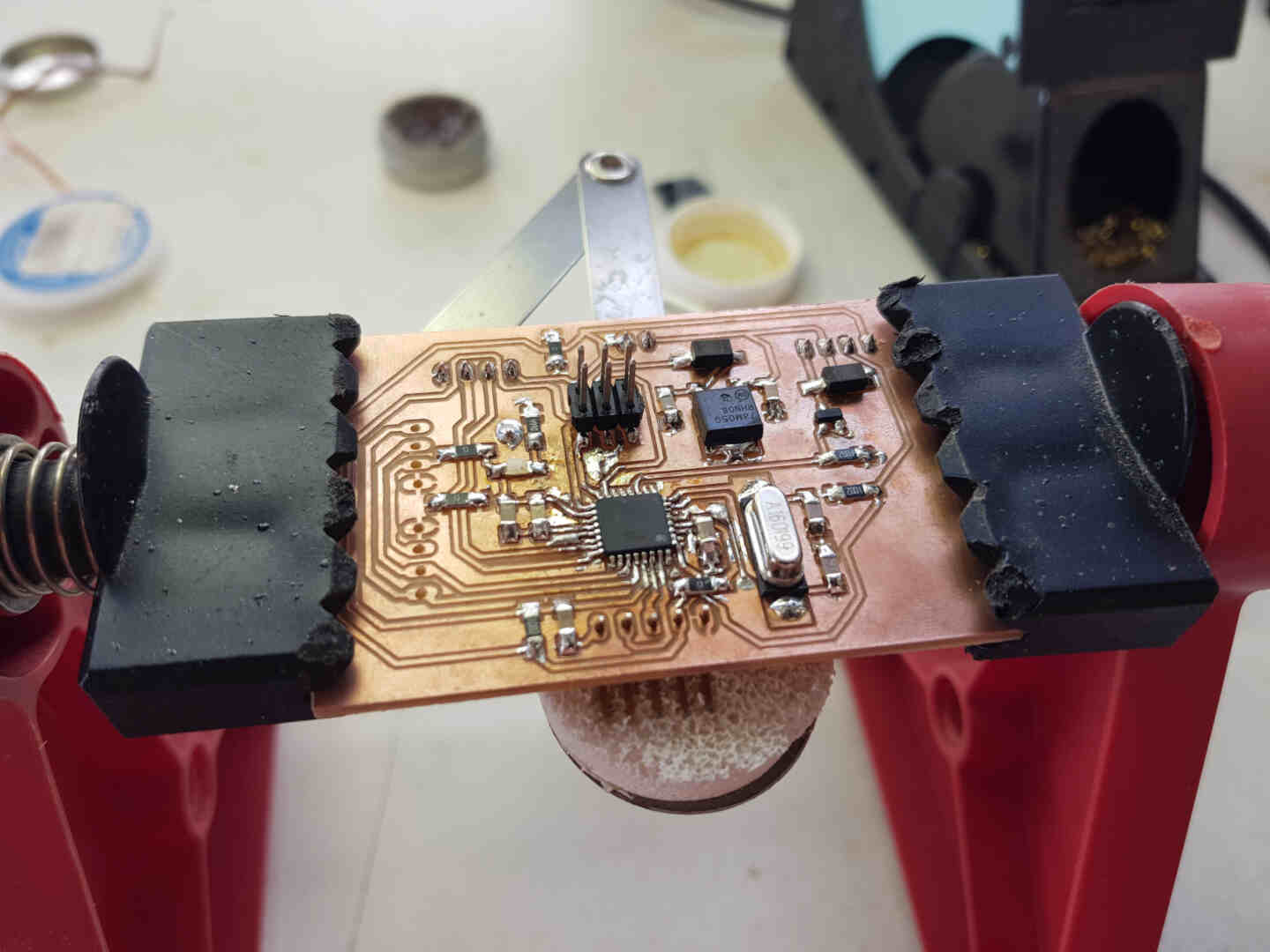
Then did the PCB design accordingly.
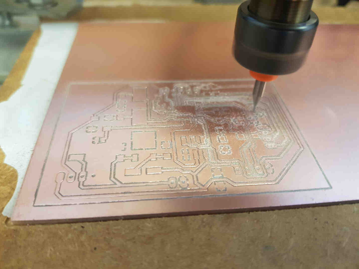
After all was ready, I used mods to create the gcode for the Genmitsu.
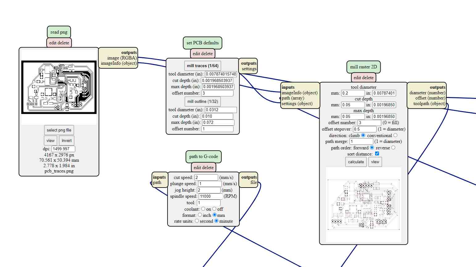
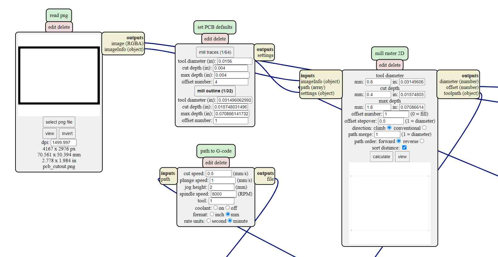
And put Genny to work.
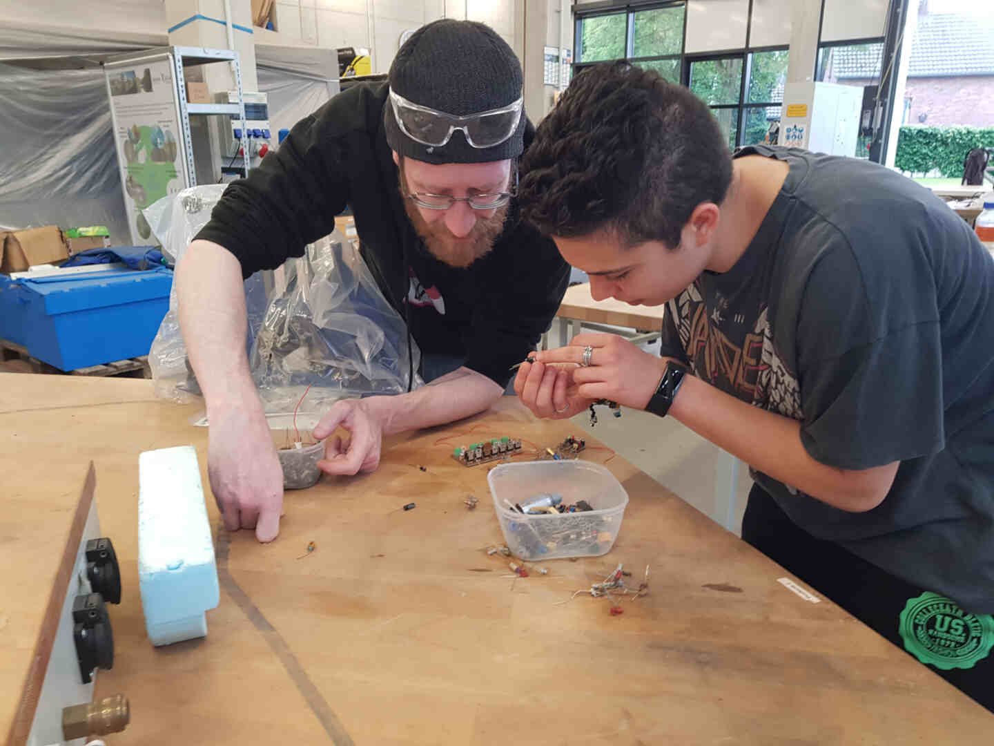
Meanwhile, Aaron and I went shopping in our ex-electronics dumpster since our electronics delivery was taking too long to arrive.
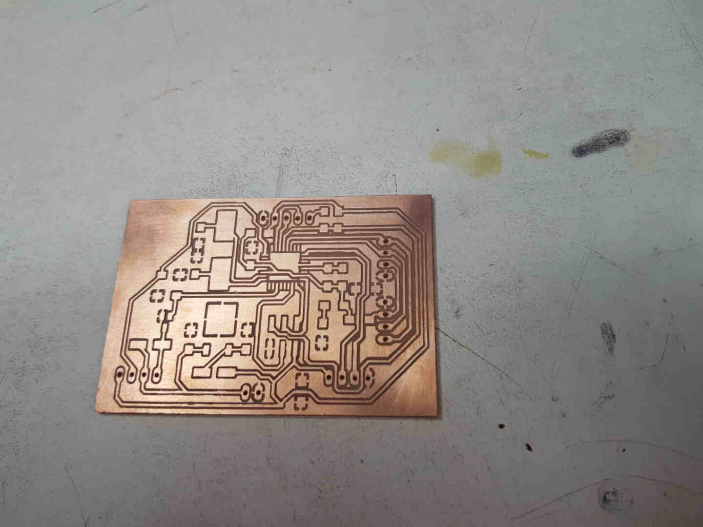
Fresh out of the oven.
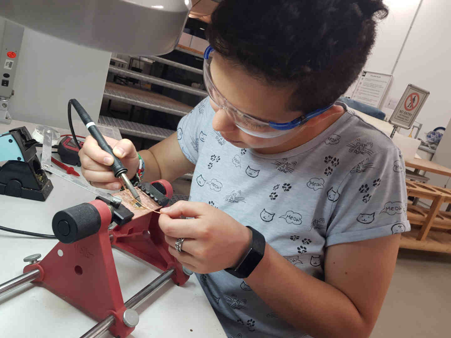
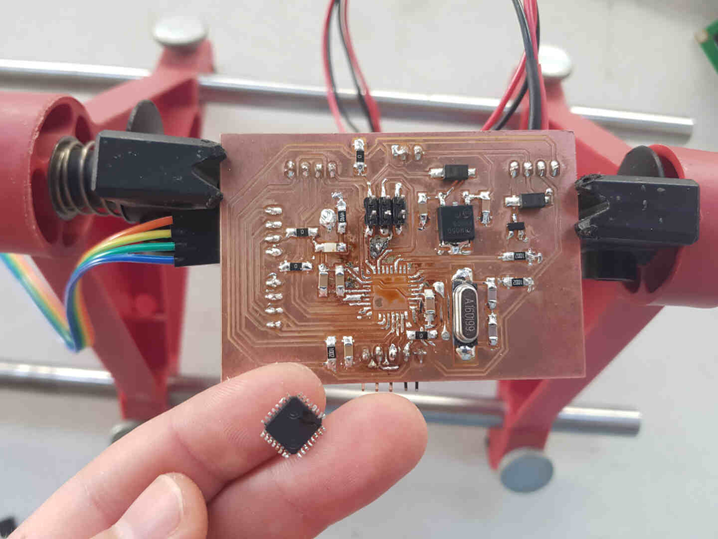
With all components acquired, I set off to stuff my PCB.
Done.
Aaaaaargh. While testing functionality with the board plugged I accidentally short-circuited the microcontroller with the multimeter probe :(. One ATmega328P later, all was good again.
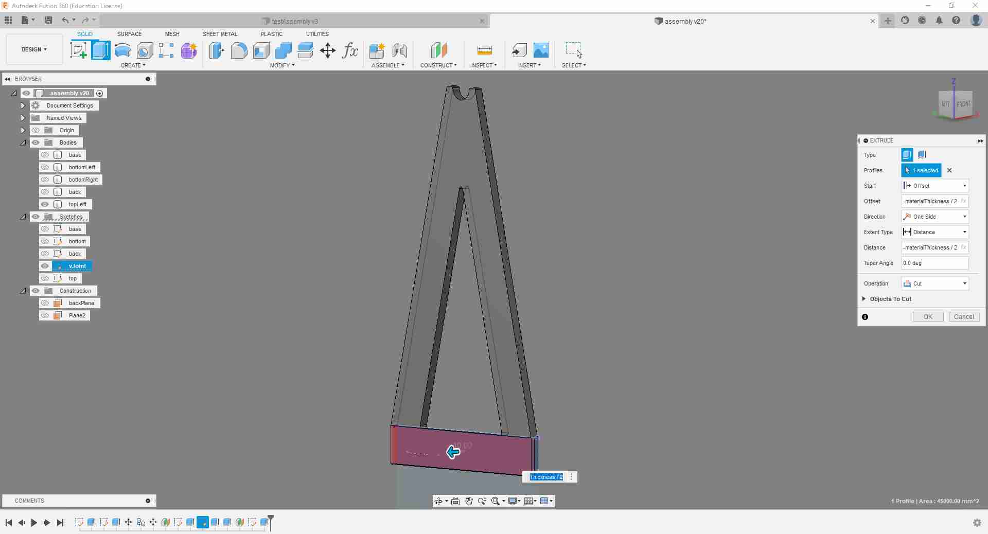
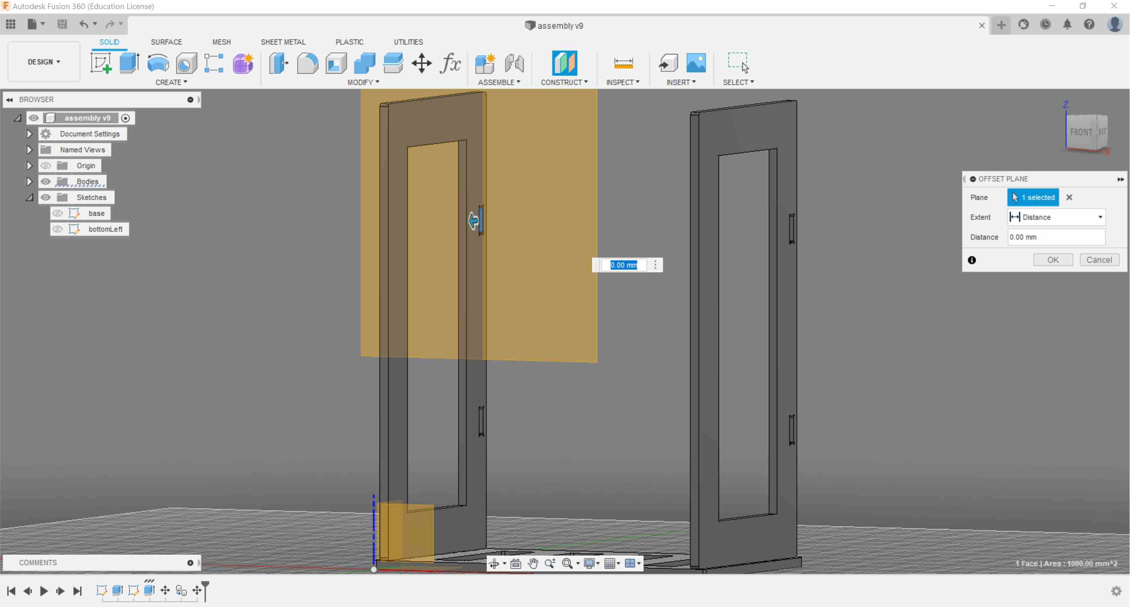
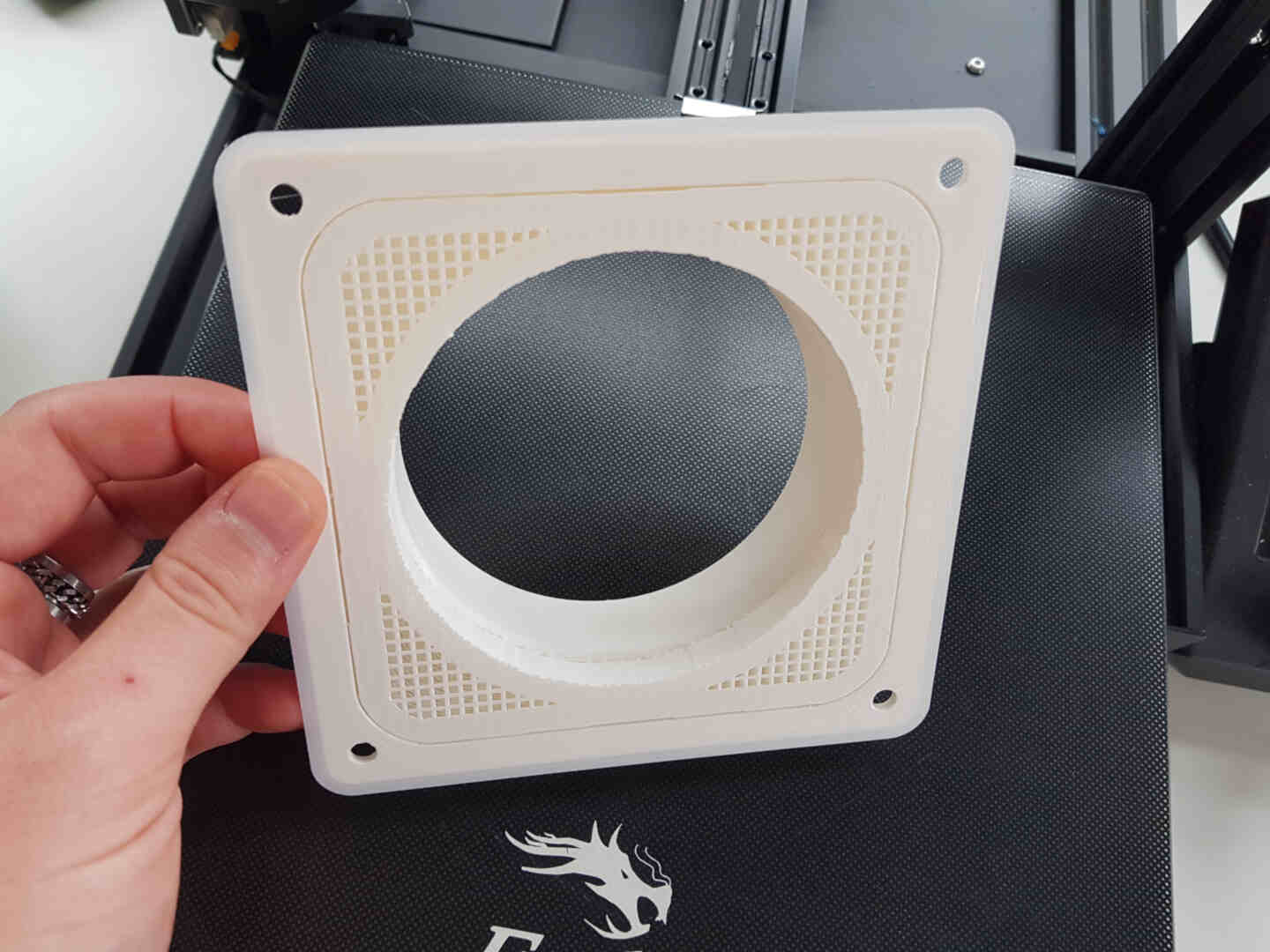
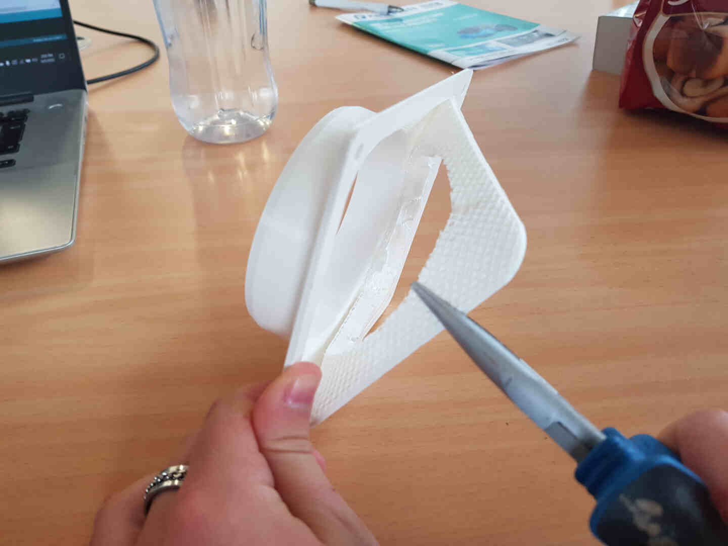
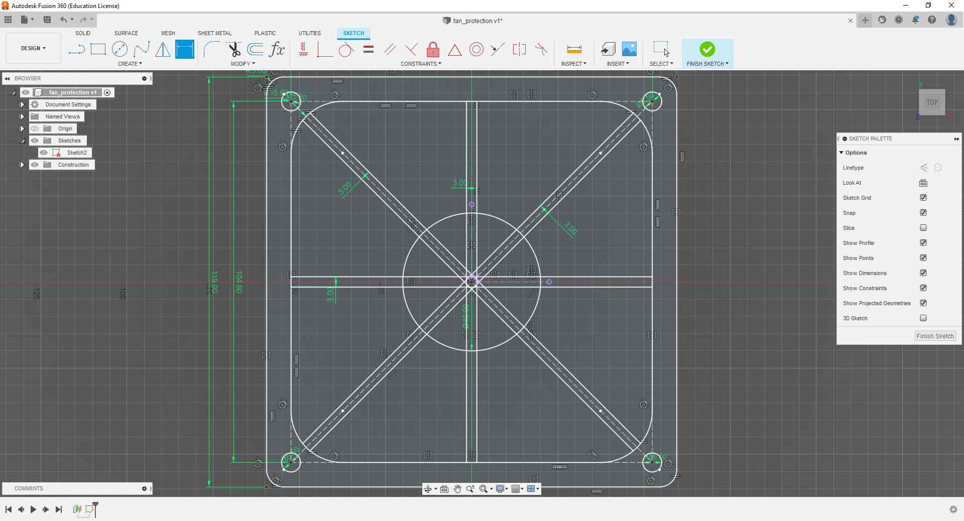
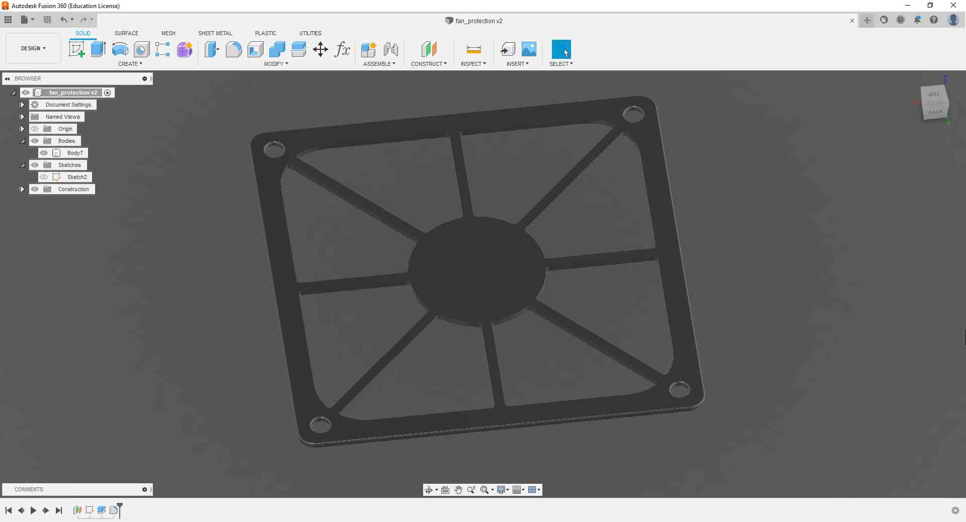
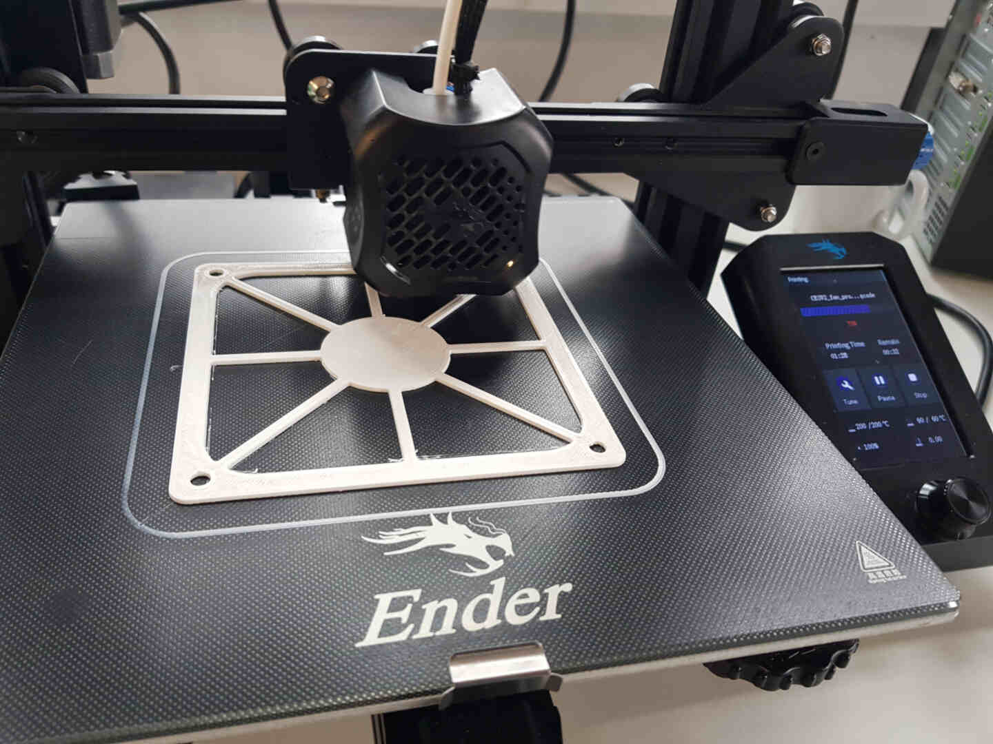
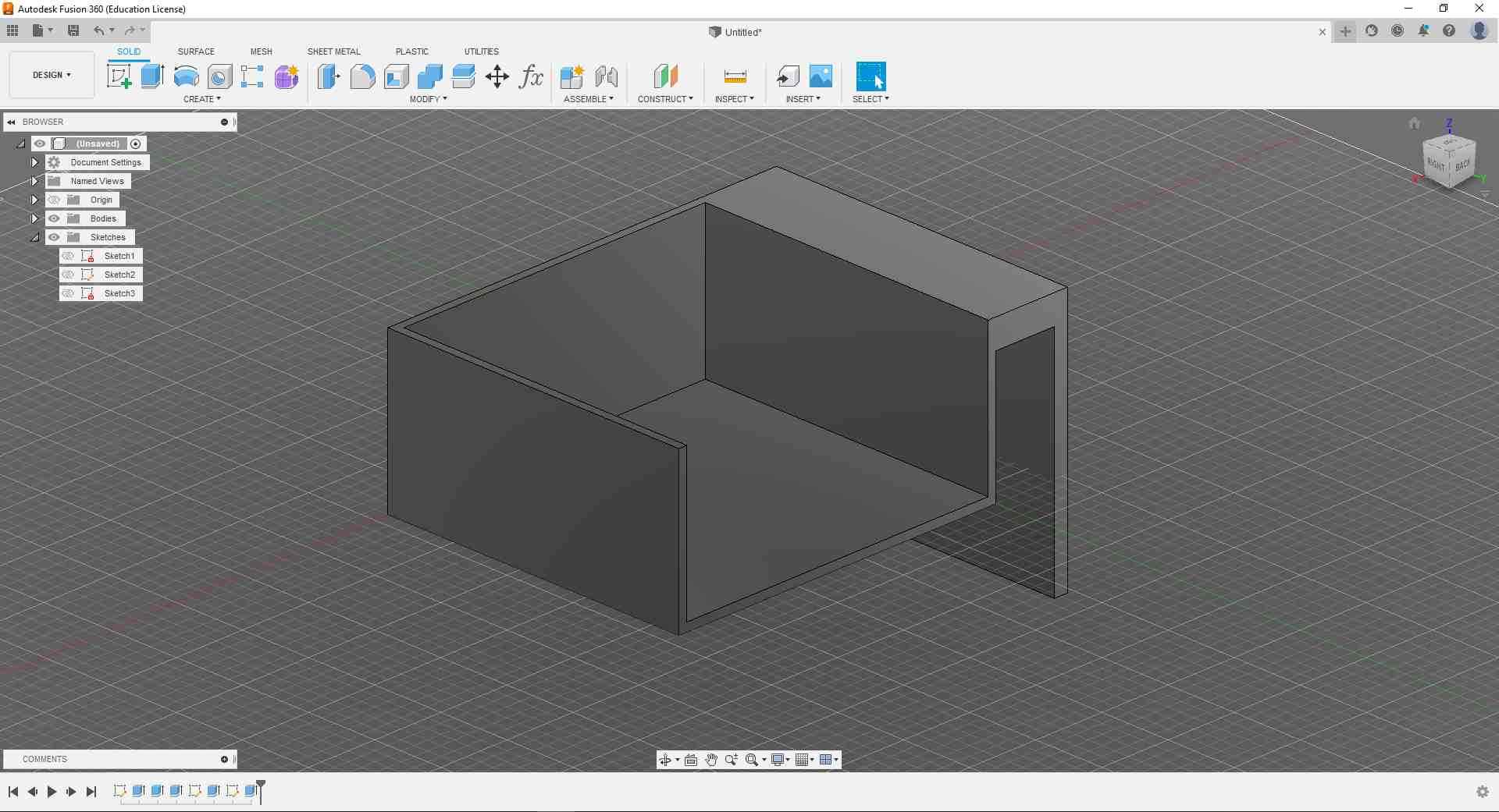
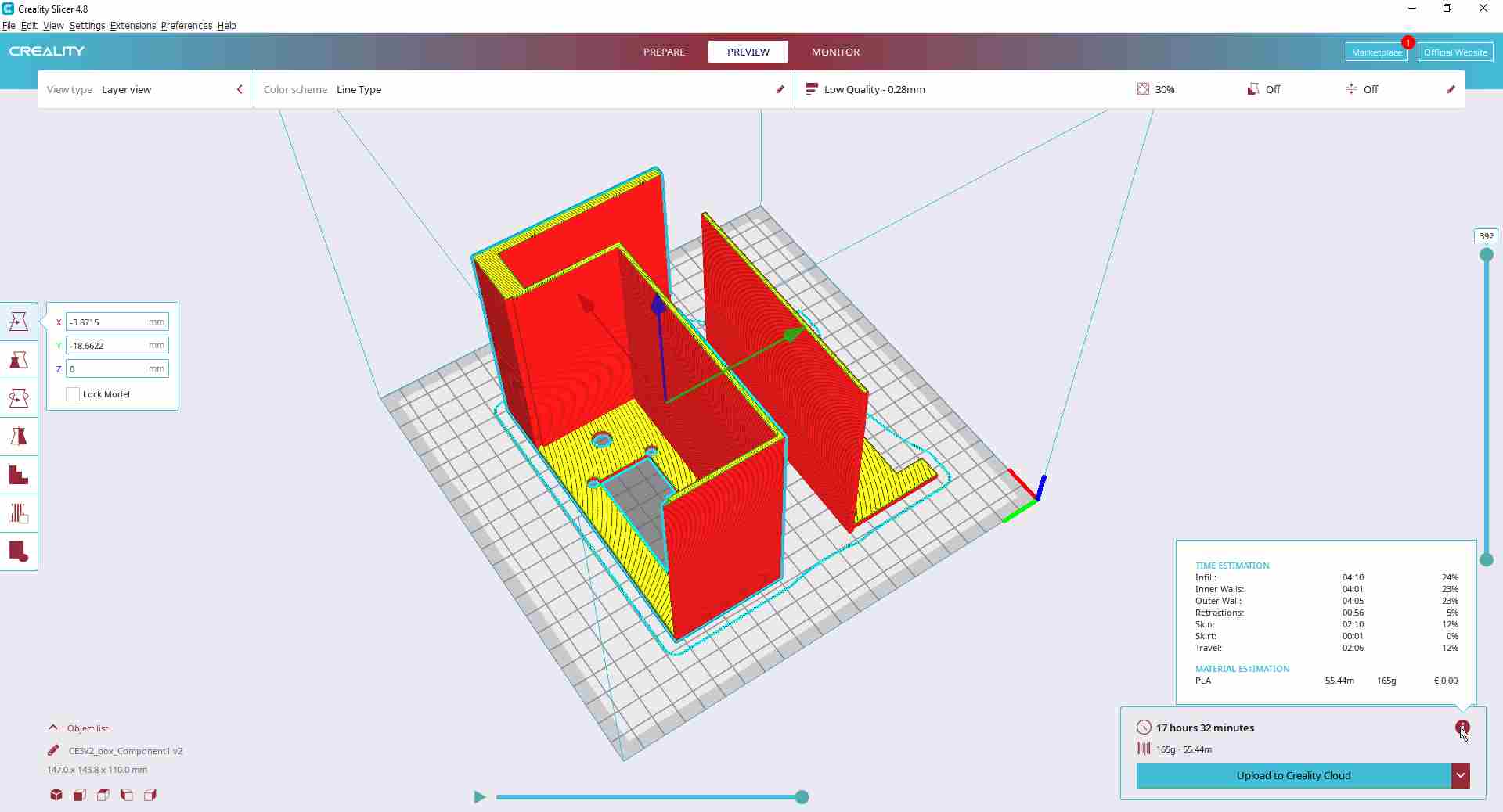
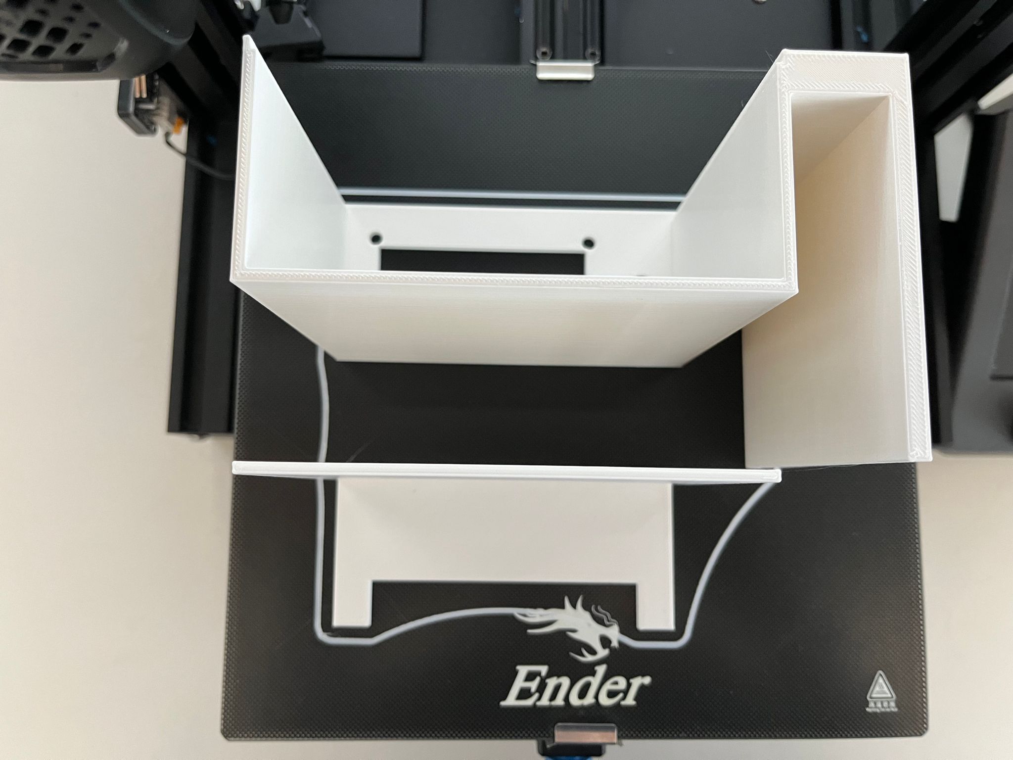
3D Printing
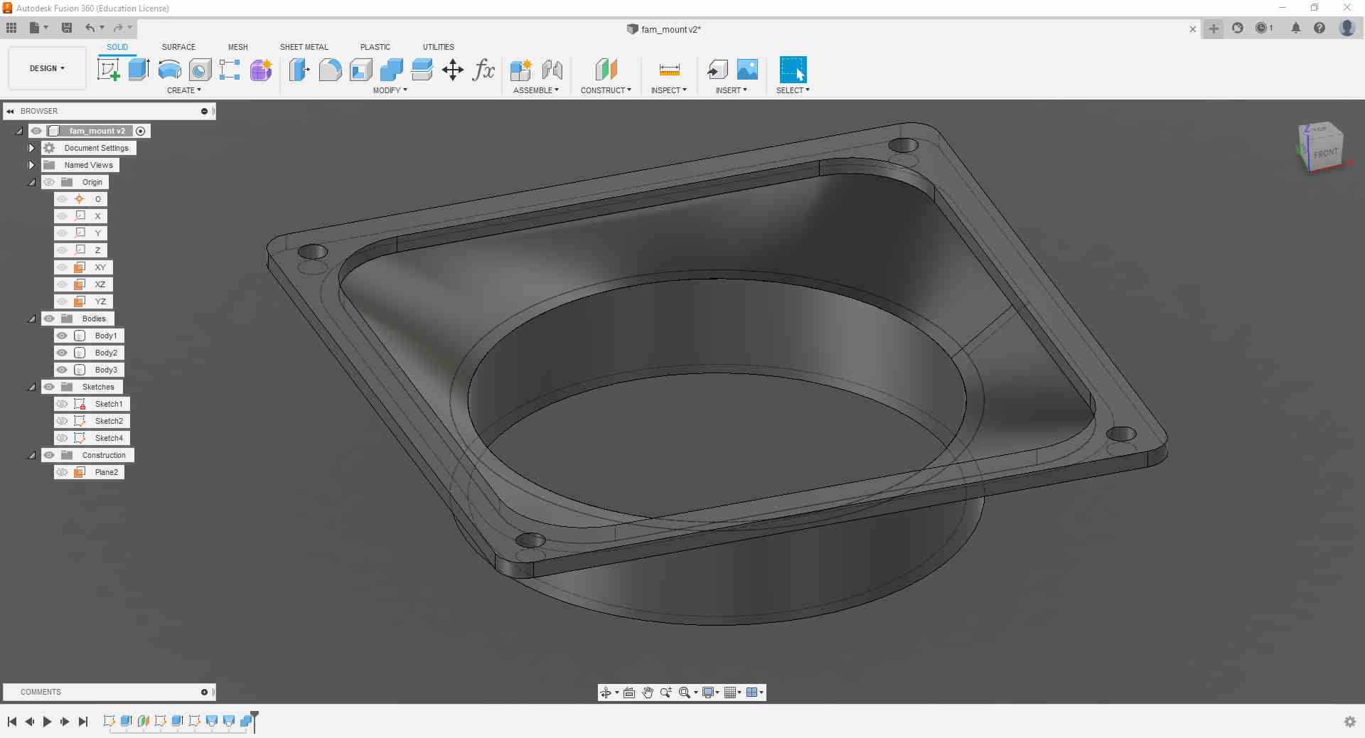
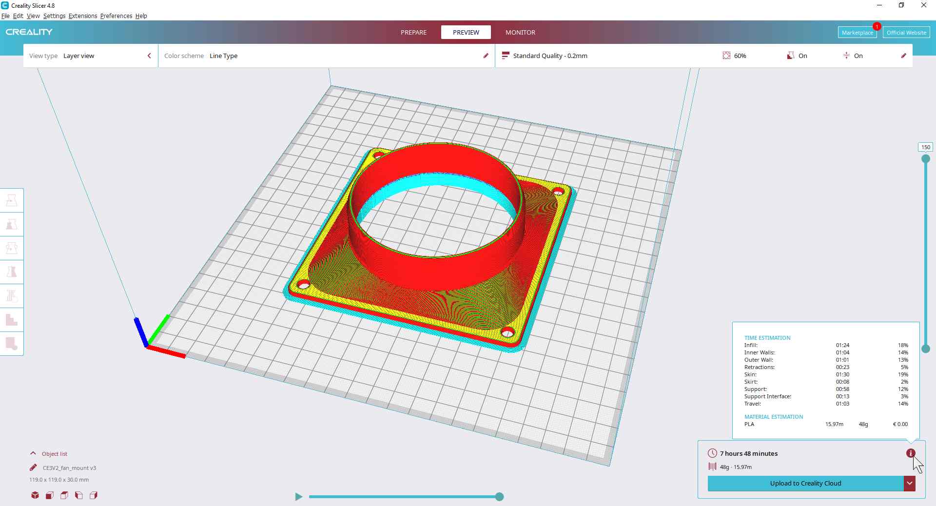
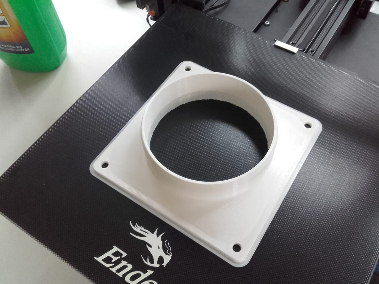
For my 3D printing, I needed to design an adapter for the fan to mount it on the PP pipe hanger, and another piece to be the fan grille. I later also needed a box to house the electronics and hang it on the rack.
I created the designs in Fusion 360, sliced them using Creality Slicer, and printed them on our Ender 3.
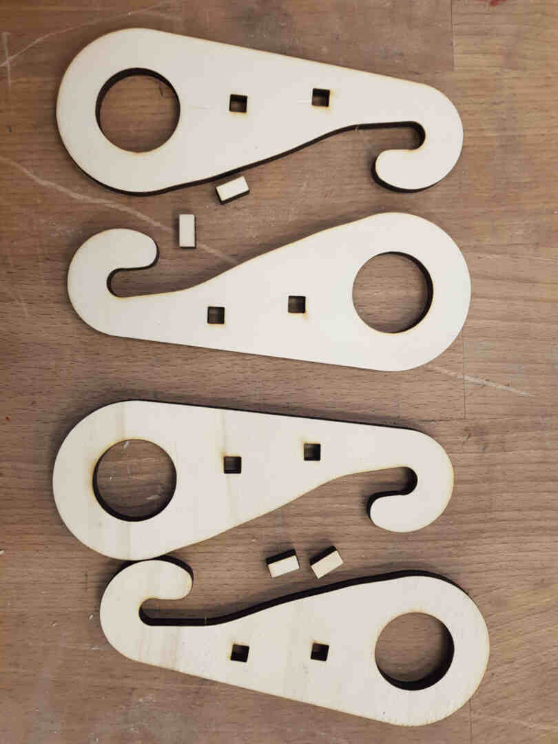
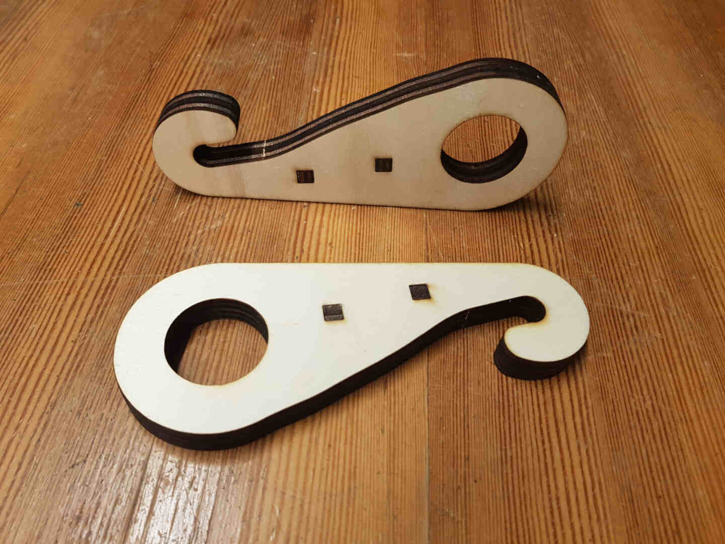
Computer-Controlled Cutting
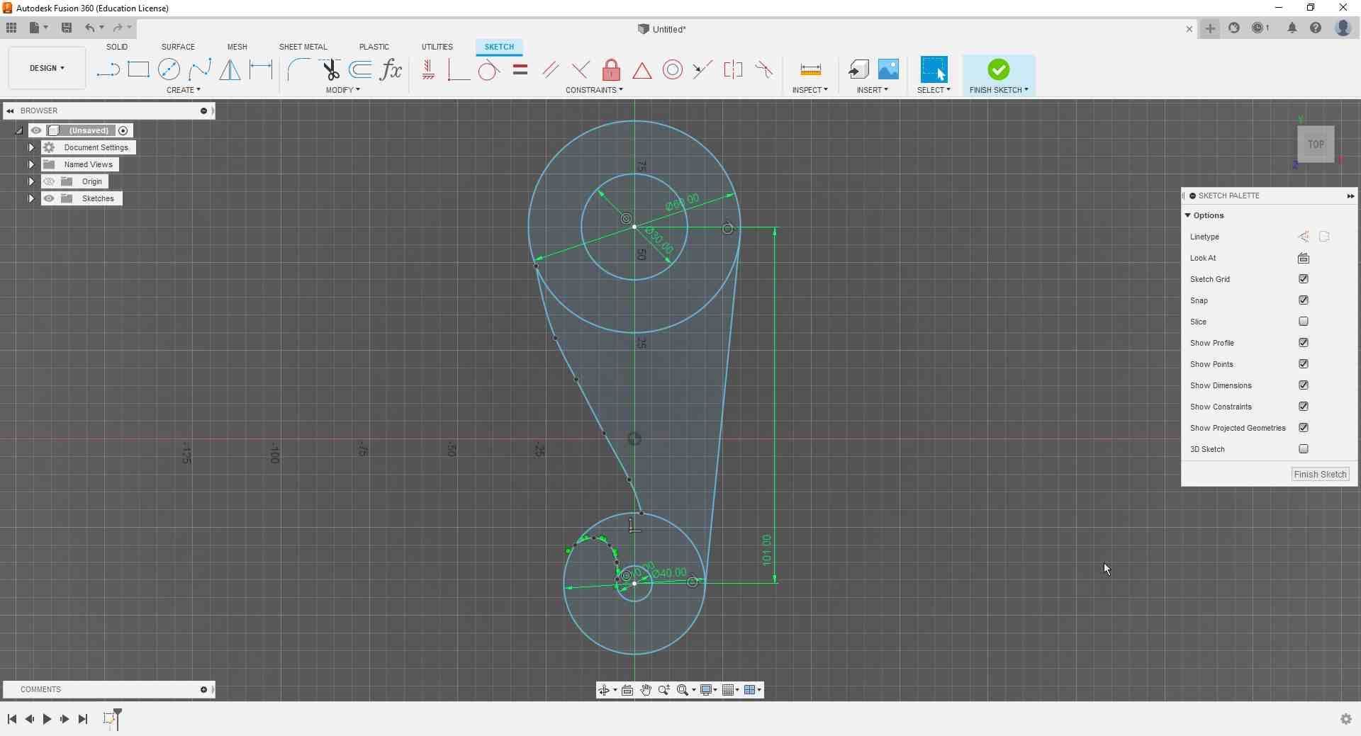
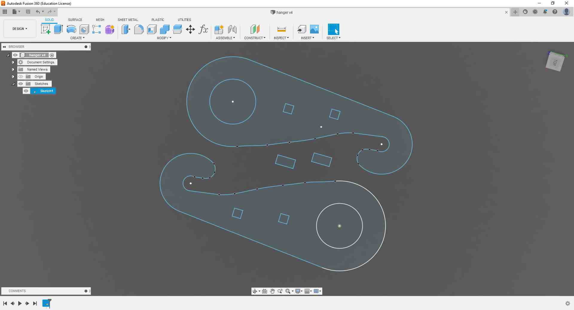
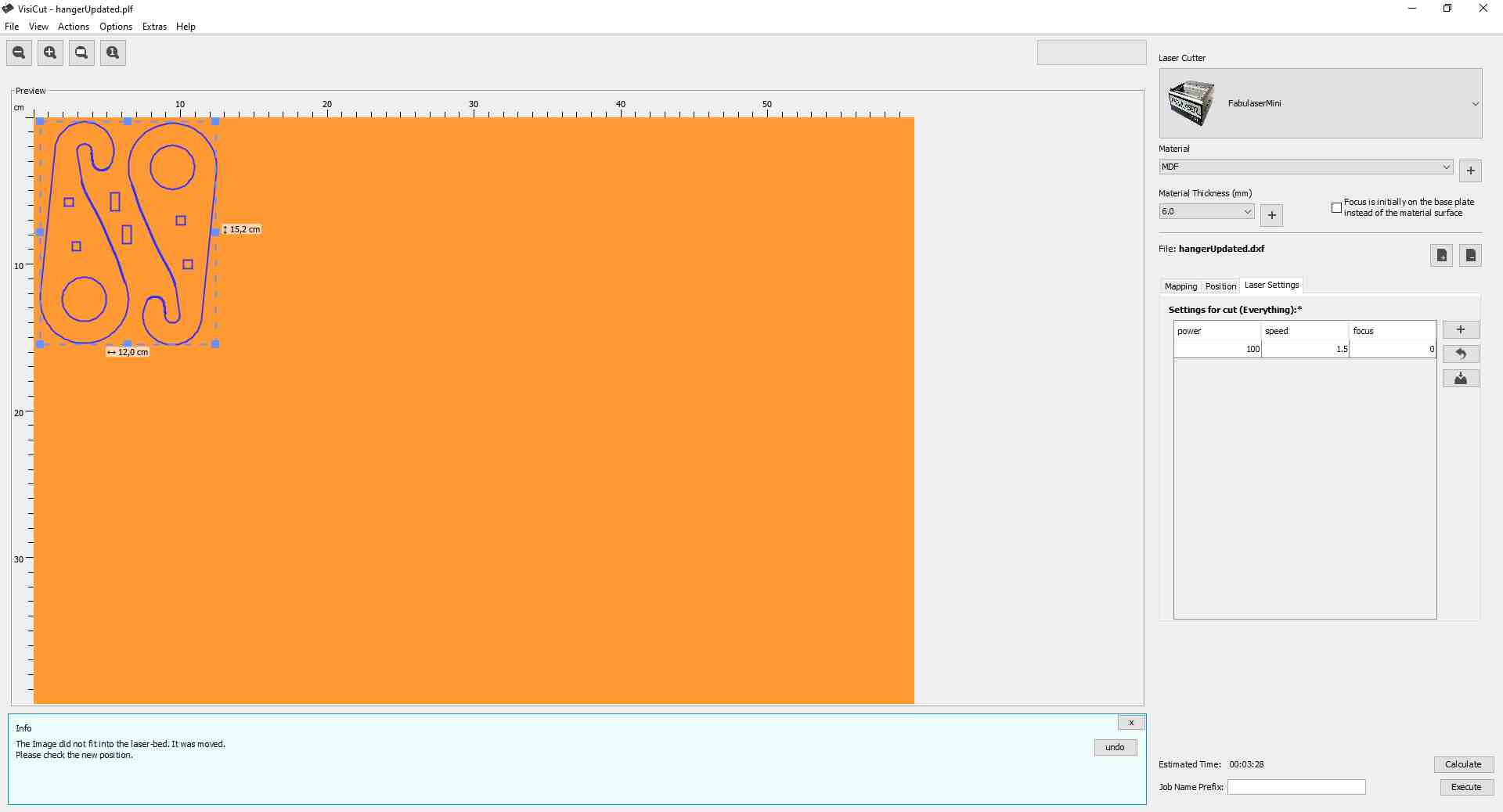
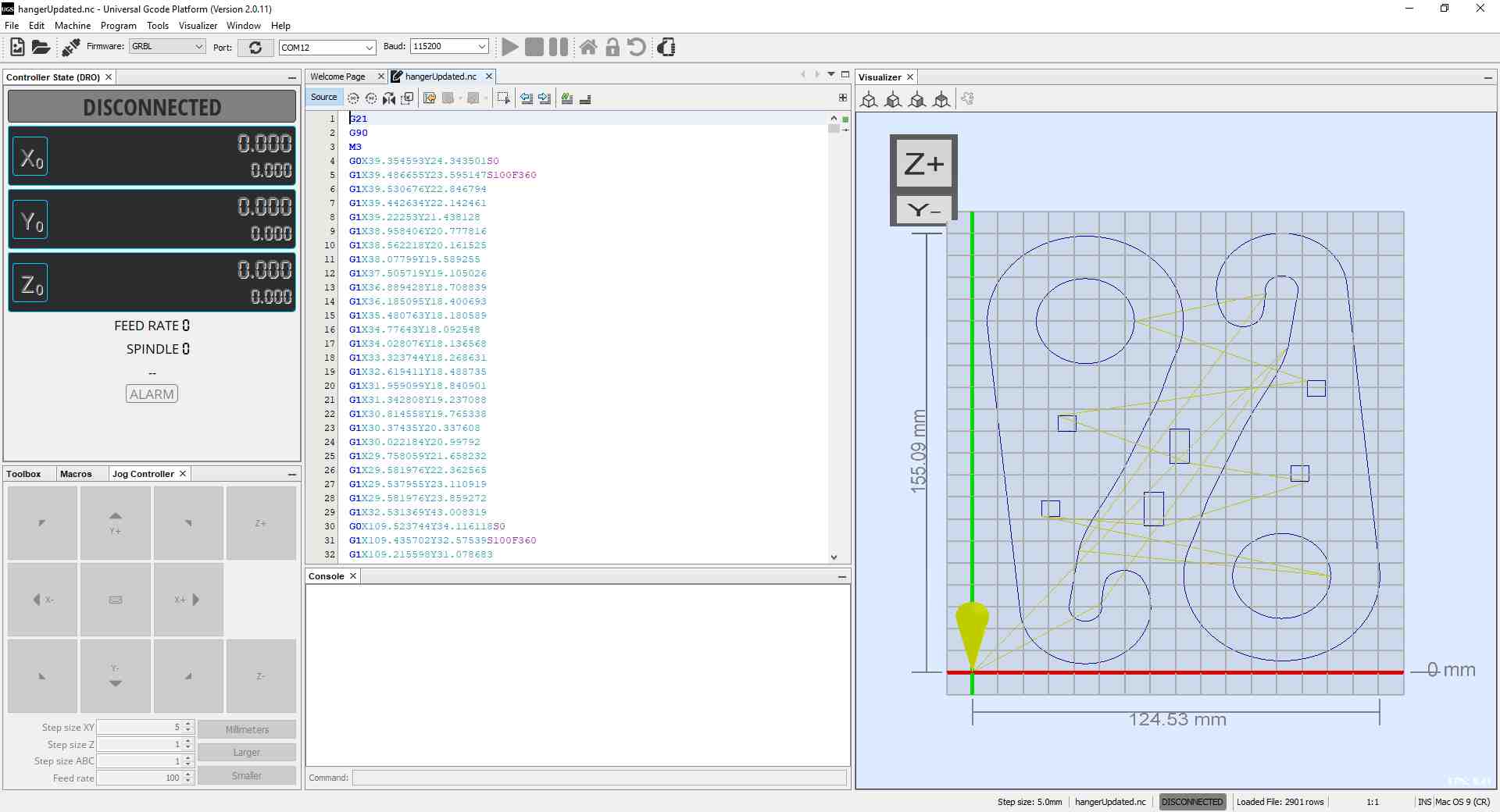
To hang my suit on the rack, I needed a sturdy hooking mechanism to bear the load. I was first planning to design something to 3D print, but then realized that I could design a hook and cut it out of plywood on our laser cutter. Satisfied with the idea, I drew the 2D outline using Fusion 360, exported the sketch as a dxf file into Visicut, and took the gcode generated and ran it in the UGS-Platform connected to the laser cutter.
I cut the hanger outlines out of 6mm-plywood, and designed two slots with interference-fit keys to fix two outlines per side and have stronger hangers.
Programming
My electronics were finally ready to be programmed, so I assembled everything and started coding.
Pseudo-Code
To wrap my head around how the outline of my program should look like, I first wrote my state-machine in pseudo-code, and replaced it bit by bit with actual code snippets. I also made sure to test each part separately before combining everything into one program.
initialize(){
	delay
	measure humidity from both sensors
	display humidity on LCD first line
	map humidity values to duty cycle values
	set flag = off
	display drying profile on LCD second line
}

main(){
	read flag
	while(flag = off){
		display drying profile on LCD second line
		read humidity sensors
		update humidity display
		pwm off
		delay
	while(flag = auto){
		display drying profile on LCD second line
		read humidity sensors
		update humidity display
		compare(sensor1 and sensor2){
			greater value is set as error signal
		}
		output pwm with duty cycle proportional to error signal
		delay
	}
	while(flag = high){
		display drying profile on LCD second line
		read humidity sensors
		update humidity display
		output pwm with maximum duty cycle
		delay
	}
	while(flag = low){
		display drying profile on LCD second line
		read humidity sensors
		update humidity display
		output pwm with minimum duty cycle
		delay
	}
}

interruptServiceRoutine(button pressed){
	if(flag = off){
		set flag = auto
		delay
		break
	}
	if(flag = auto){
		set flag = high
		delay
		break
	}
	if(flag = high){
		set flag = low
		delay
		break
	}
	if(flag = low){
		set flag = auto
		delay
		break
	}
}
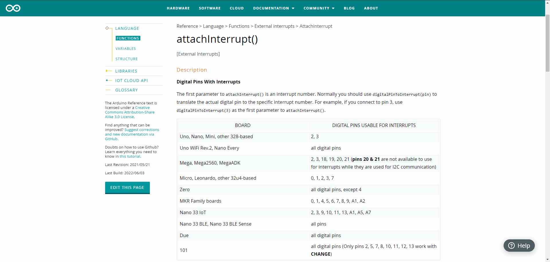
I also had to teach myself how to use the attachInterrupt() function, since I've never programmed anything with interrupts before. Additionally, I had to make sure that I incorporate some kind of debounce code for my push button to avoid faulty behavior.
The Real Deal
Here is my code in full:
- In the Libraries section, I called the libraries I installed to run the I2C LCD module and the humidity sensor module.
- In the Pinout section, I declared all the physical connections between the microcontroller and the peripherals.
- In the Variables and Definitions and Instances sections, I declared all parameters used in the code.
- In the Setup section, I defined the type of pins each peripheral is connected to, and took care of all initializations that need to be done at machine startup.
- In the Main loop, I checked for the state of the flag that indicated that the button was pressed, and then used a switch-case structure to deal with the current state of the flag. In those cases, I either turned off the fan, used the maxHumidity variable to set the duty cycle and frequency of the signal, turned the fan on the lowest speed, or set it to the highest speed. I also called functions that I wrote outside the main loop to perform LCD-related tasks.
- The function buttonPressed() is my interrupt service routine. It gets called every time the button is pressed, and I used it to set an interrupt flag that gets processed in the main loop.
- The functions printOff(), printAuto(), printLow(), and printHigh() display the name of the current mode, read the humidity values from both sensors, and output the higher reading on the LCD.
// Libraries
#include <LCD_I2C.h>
#include <DHT.h>

// Pinout
const int hs1Pin = A0;
const int hs2Pin = A1;
const int buttonPin = 3;
const int fanPin = 7;

// Variables and Definitions
#define DHTTYPE DHT11
int mode = 0;        // 0: off, 1: auto, 2: low, 3: high
volatile bool interrupted = false;
volatile float humid1 = 0;
volatile float humid2 = 0;
volatile int maxHumidity = 0;
const int lowSpeed = 10;
const int highSpeed = 100;

// Instances
LCD_I2C lcd(0x27, 16, 2);
DHT hs1(hs1Pin, DHTTYPE);
DHT hs2(hs2Pin, DHTTYPE);

// Setup
void setup() {
	// put your setup code here, to run once:
	pinMode(hs1Pin, INPUT);
	pinMode(hs2Pin, INPUT);
	pinMode(buttonPin, INPUT);
	pinMode(fanPin, OUTPUT);
	attachInterrupt(digitalPinToInterrupt(buttonPin), buttonPressed, RISING);
	lcd.begin();
	lcd.backlight();
	hs1.begin();
	hs2.begin();
	lcd.clear();
	lcd.print("Hello :)");
	delay(2000);
	lcd.clear();
}

// Main
void loop() {
	if(interrupted == true){
	delay(500);
	interrupted = false;
	mode++;
	if(mode > 3){
		mode = 0;
	}
	}
	switch(mode){
	case 0:
		printOff();
		digitalWrite(fanPin,LOW);
		delay(1000);
		break;
	case 1:
		printAuto();
		digitalWrite(fanPin, HIGH);
		delay(maxHumidity * 10);
		digitalWrite(fanPin, LOW);
		delay(100 - maxHumidity);
		break;
	case 2:
		printLow();
		digitalWrite(fanPin, HIGH);
		delay(100);
		digitalWrite(fanPin, LOW);
		delay(100);
		break;
	case 3:
		printHigh();
		digitalWrite(fanPin,HIGH);
		delay(1000);
		break;
	}
}

void buttonPressed(){
	interrupted = true;
}

void printOff(){
	humid1 = hs1.readHumidity();
	humid2 = hs2.readHumidity();
	lcd.setCursor(0, 0);
	lcd.print("Mode: Off ");
	lcd.setCursor(0, 1);
	lcd.print("Humidity: ");
	lcd.setCursor(10, 1);
	if (humid1 > humid2){
	maxHumidity = int(humid1);
	} else {
	maxHumidity = int(humid2);
	}
	lcd.print(maxHumidity);
	lcd.print("%");
}

void printAuto(){
	humid1 = hs1.readHumidity();
	humid2 = hs2.readHumidity();
	lcd.setCursor(0, 0);
	lcd.print("Mode: Auto");
	lcd.setCursor(0, 1);
	lcd.print("Humidity: ");
	lcd.setCursor(10, 1);
	if (humid1 > humid2){
	maxHumidity = int(humid1);
	} else {
	maxHumidity = int(humid2);
	}
	lcd.print(maxHumidity);
	lcd.print("%");
}

void printLow(){
	humid1 = hs1.readHumidity();
	humid2 = hs2.readHumidity();
	lcd.setCursor(0, 0);
	lcd.print("Mode: Low ");
	lcd.setCursor(0, 1);
	lcd.print("Humidity: ");
	lcd.setCursor(10, 1);
	if (humid1 > humid2){
	maxHumidity = int(humid1);
	} else {
	maxHumidity = int(humid2);
	}
	lcd.print(maxHumidity);
	lcd.print("%");
}

void printHigh(){
	humid1 = hs1.readHumidity();
	humid2 = hs2.readHumidity();
	lcd.setCursor(0, 0);
	lcd.print("Mode: High");
	lcd.setCursor(0, 1);
	lcd.print("Humidity: ");
	lcd.setCursor(10, 1);
	if (humid1 > humid2){
	maxHumidity = int(humid1);
	} else {
	maxHumidity = int(humid2);
	}
	lcd.print(maxHumidity);
	lcd.print("%");
}
The Plan Going Forward
For the time being, I intend to enjoy and be satisfied with my creation. I am proud of what I was able to build, and SSD will -hopefully- be enjoying a busy summer ahead working hard drying my scuba suit :). If I ever decide to spiral further, I would probably integrate a heating element or a de-humidifier unit to speed up the drying process, but for now this will do. Another area of improvement is waterproofing the whole system, but for now placing a plastic box under the hanging suit is more than enough. The beauty of SSD in its current form is that I can take the electronics unit and use it while traveling. I just need to maybe create a hook for the hanger that could be mounted on a wall hook or a different rack. At this point, I do not plan on selling any SSD units or anything; it's all documented here and whoever has the means is free to make one for themselves (minding of course the extent of their rights to do so). I just intend to put SSD to work and see what user feedback I get from myself :D.