Leen Nijim
Assignment 8
Computer-Controlled Machining
Task
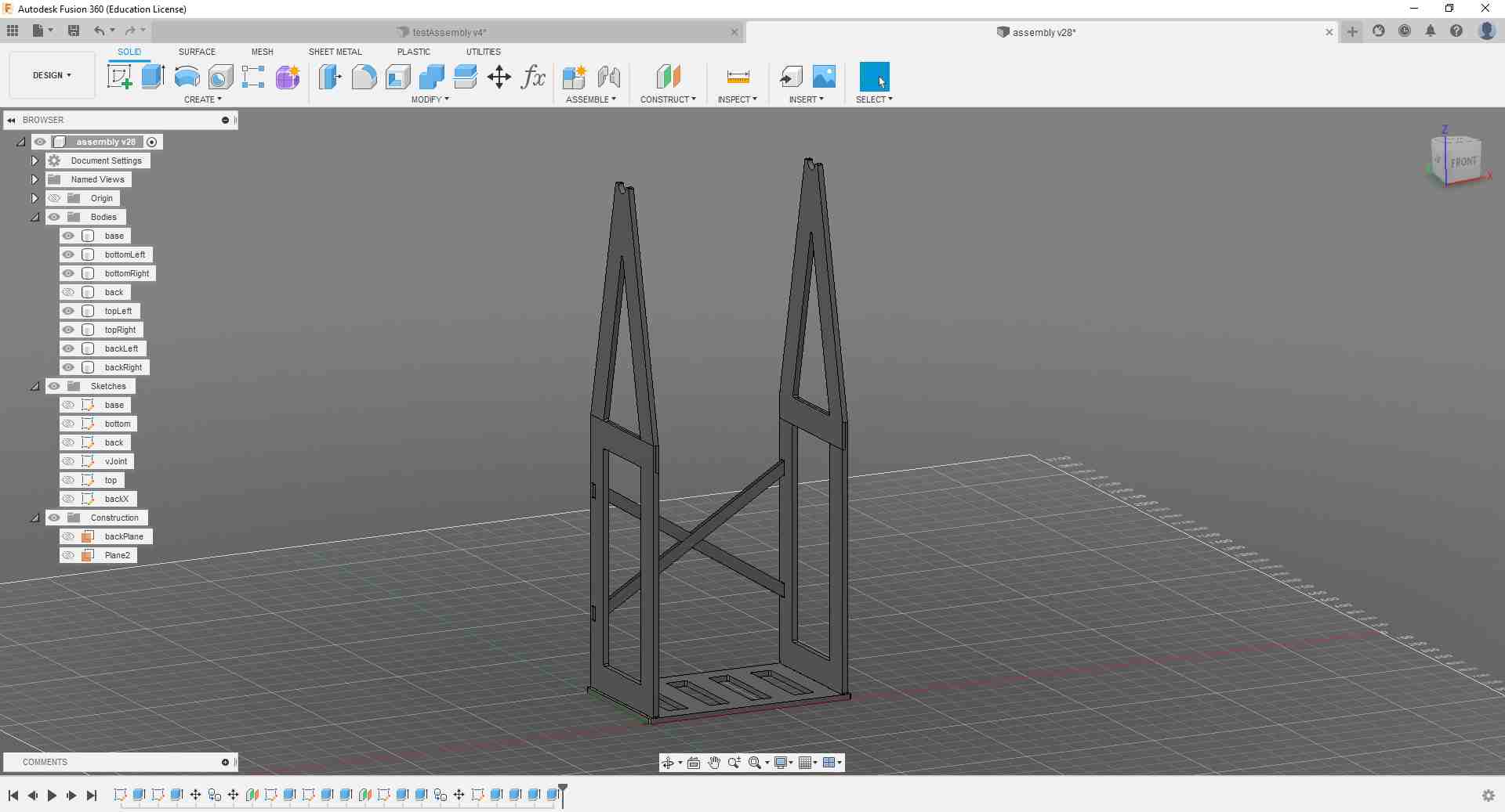
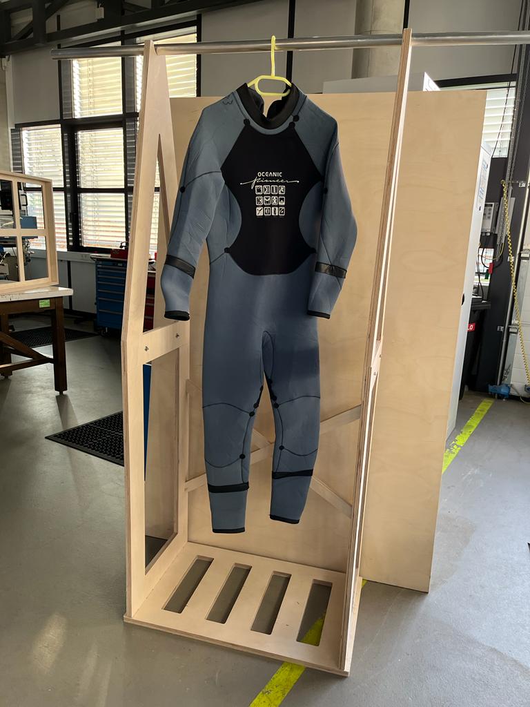
This week we had to make something big! So I took the opportunity to contribute to my final project by building the 2m-high hanging rack for my dive suit. To do so, I designed the model in Fusion 360, milled it on our CNC, and assembled it.
What You Need
- Access to CNC machine.
- Wood board 250 x 126 x 2 cm.
- Some woodworking tools like mallet, chisels, and box cutter knife.
Files to Download
Hero Shots
Group Assignment
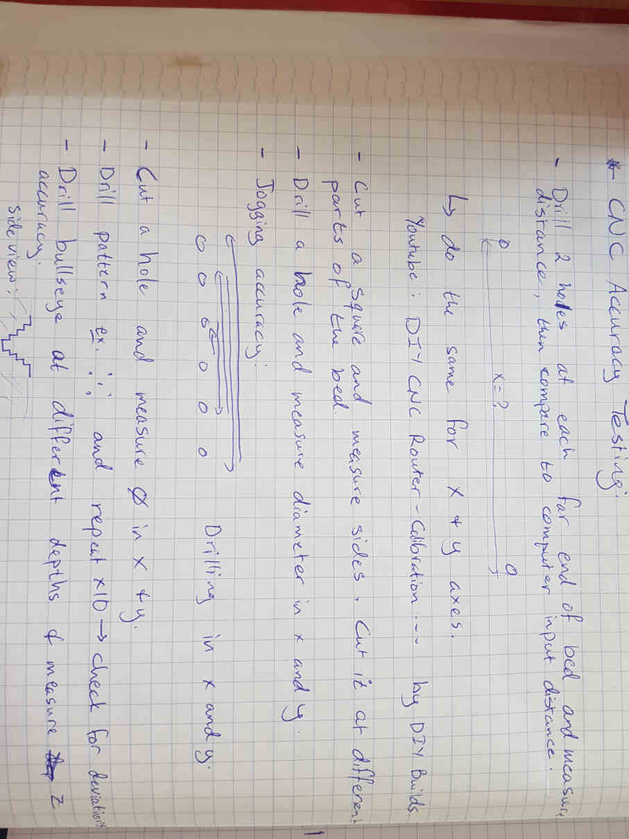
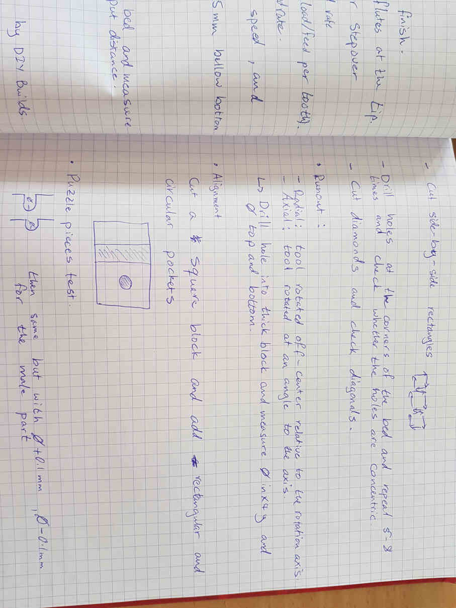
For the group assignment, please click here. This time, we had to go through the safety protocols for our workshop area and the CNC machine, and had to make sure we wear appropriate clothing and protection equipment like steel-toe shoes, tigh-fitting clothes, eye protection and, when necessary, ear protection. We then had to do some tests for our CNC machine for which I did the research for appropriate tests and designed a simple CAD model to be run on the CNC.
Here are some notes I took while looking through internet forums:
And here is the test piece I designed.
.jpg)
.jpg)
.jpg)
Making Something Big :D
Here, I designed the rack model and small joint test to be CNCed, and then milled and assembled the rack.
Designing the 3D Model in Fusion 360
I started by sketching the base part of the rack and added dog bone slots for the joints. I made my design parametrically so that whenever I need to change a value, especially in the joints areas, I could do so easily. However, I must admit that by doing that I spent a lot more time on the design phase compared to what I could have done without parametric design.
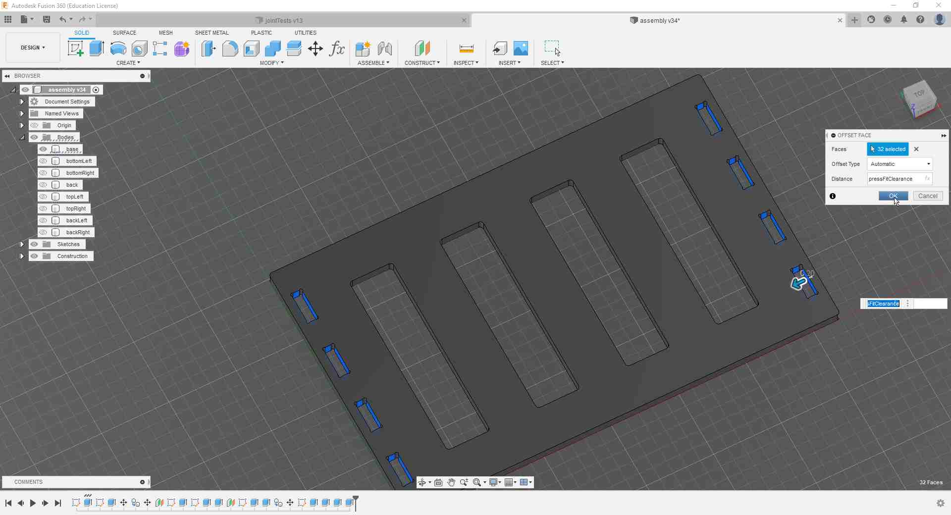
Anyway, I designed the joint slots with zero clearance first and intended to correct for that after I have done my CNC mini joint test.
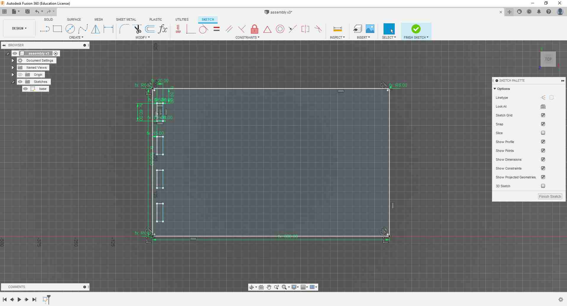
I then added some slots in the middle to slightly reduce the weight of the rack and to add some ventilation to the underside as it will be in a humid environment. I also intend to hammer some rubber feet to give the rack some elevation off the floor.
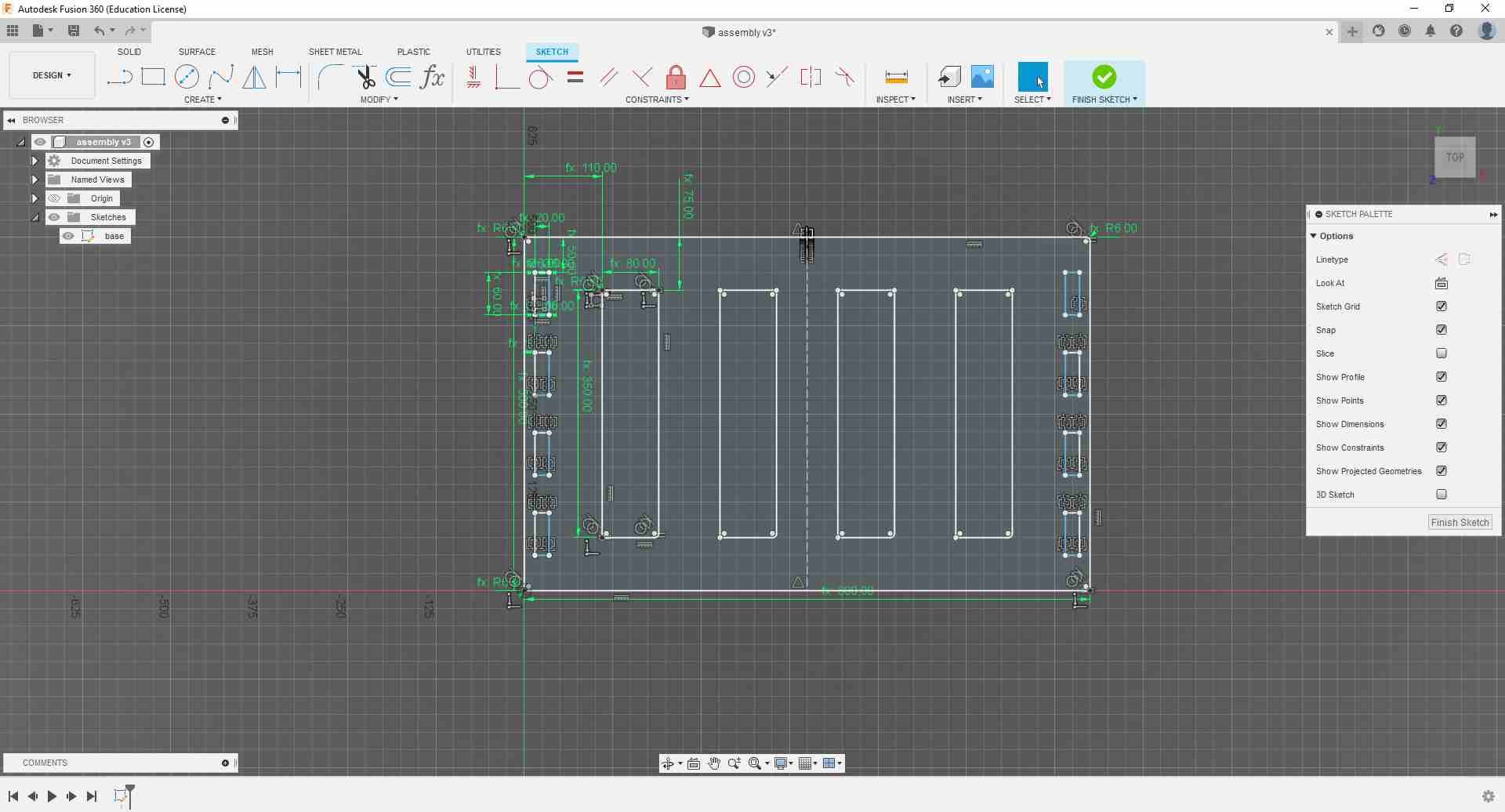
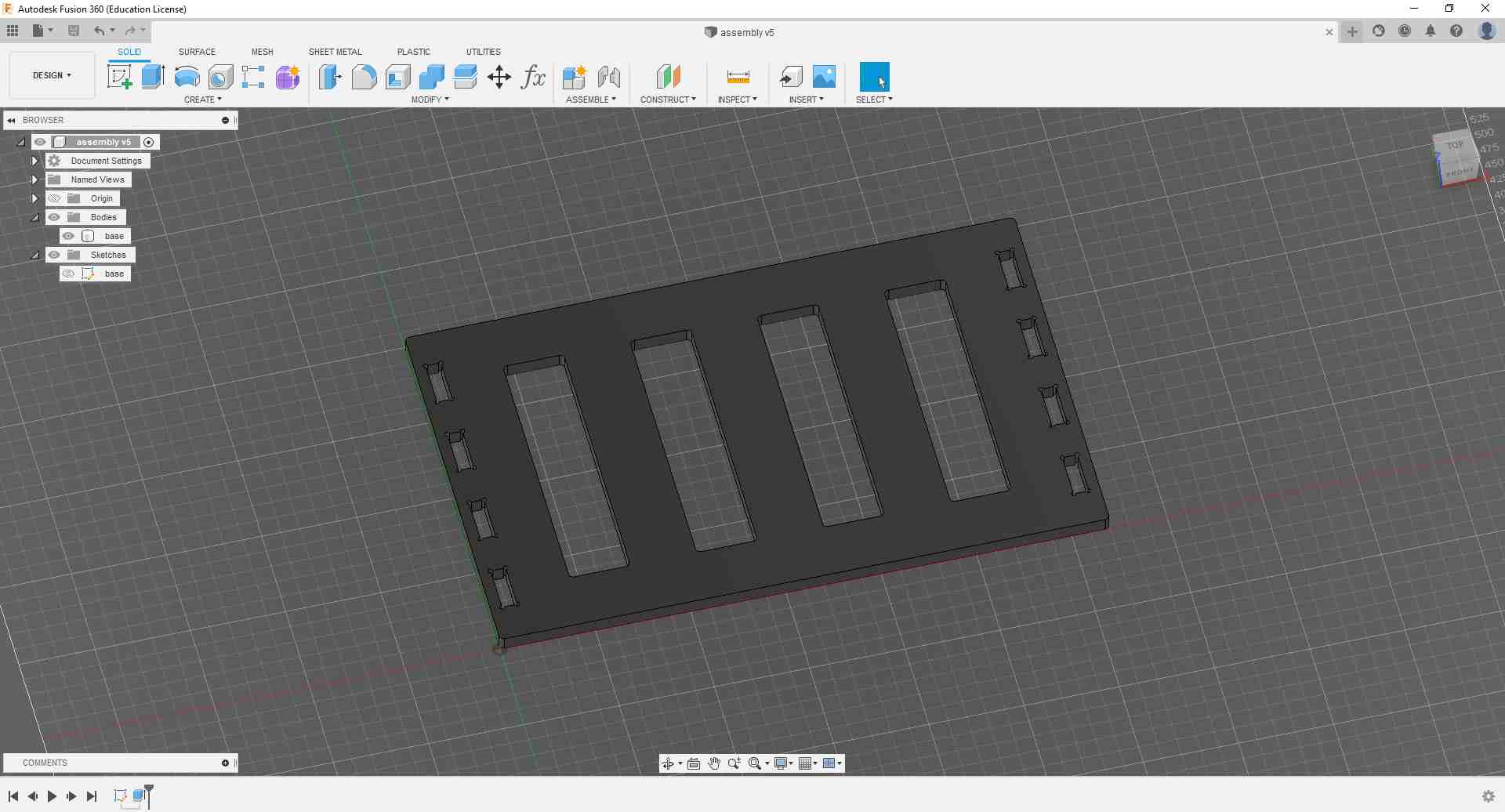
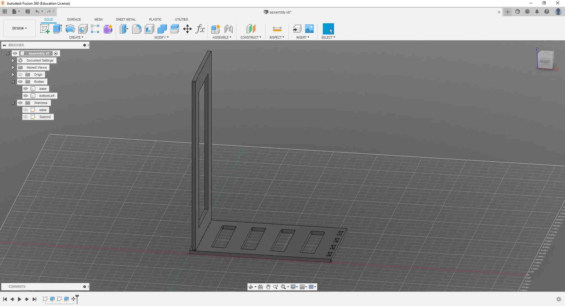
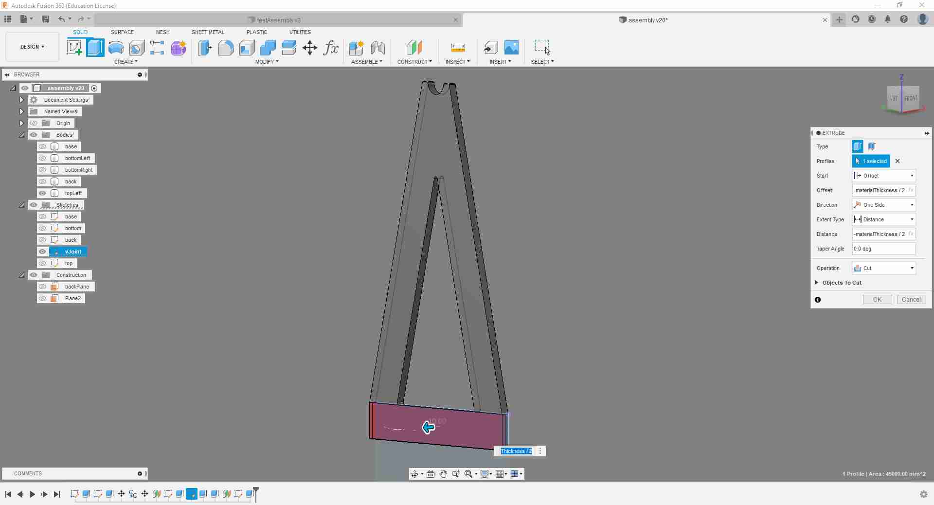
Here is the extruded base.
Next step was to design the lower side panels for the rack. Here it is worth noting that corner designs need to be done with the milling tool in mind: depending on the corner's orientation, the fillets should be at least the size of the tool diameter they are to be CNCed with. Since I am planning to avoid any tool changes and just use a 6 mm flat end mill, I unified my fillet diameters to 6 mm.
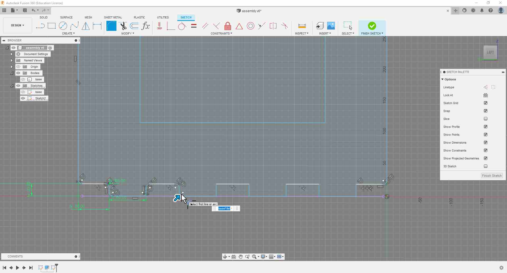
Here is how the model is developing.
I then used the Move/Copy function to create another side panel. The advantage of copying it this way, is that both sides stay linked design-wise, so that if I apply changes to the original one both will be updated.
.jpg)
It was good that I had the used the function described above because I later realized that I forgot to add dog bone slots for the joint with the back piece.
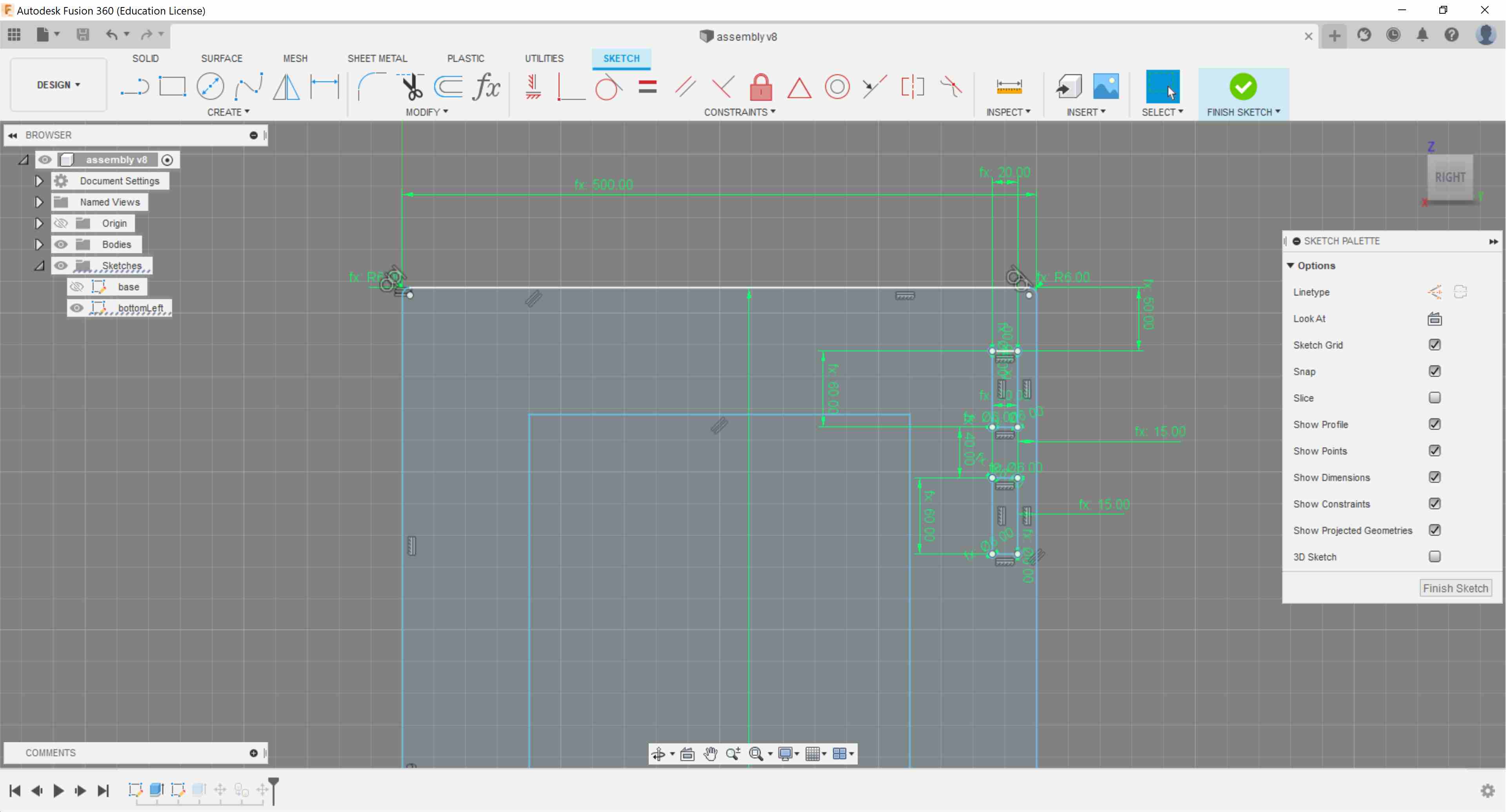
After that I cleated a plane at the inside of the side panel slot in preparation for sketching the back piece.
Here is the design of the back.
It was very useful to toggle the Hide/Show function of the side panels to make sure that my dimensions fit.
And now here is the extruded back side. This is the design that I intend to submit for my task this week.
Extra Designs for the Actual Rack
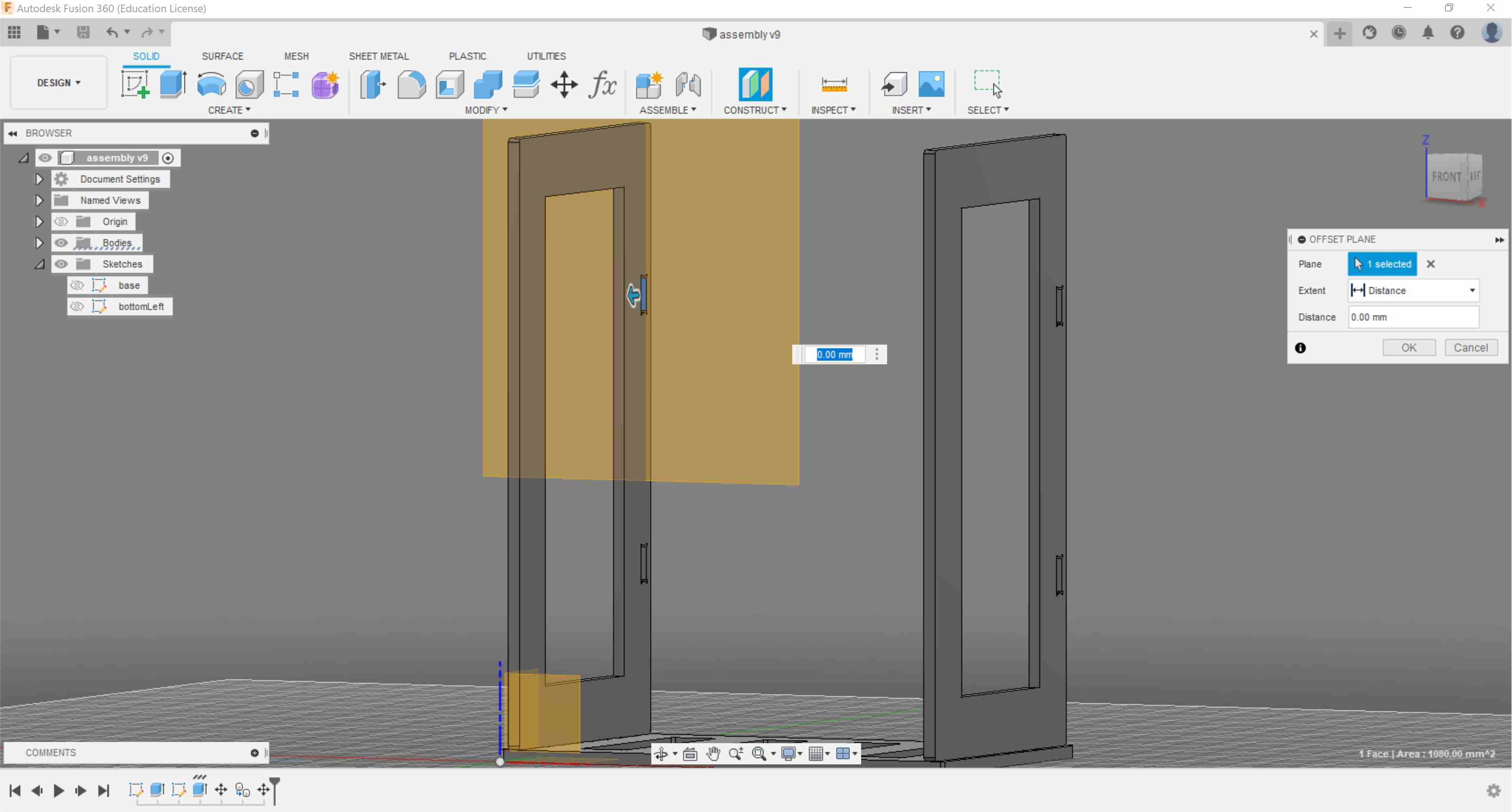
By now, I have decided that I would like to use screws to mount the top sides of the rack to the bottom design. This came after a conversation with my fellow fabmate Aaron in which we concluded that using screws would be the easiest way to allow me to disassemble that rack and transport it. So I added a pocket to each side where the top sides will be fastened to.
.jpg)
Then I went on to design the top sides on which I will mount an aluminum rod to hang the suit on.
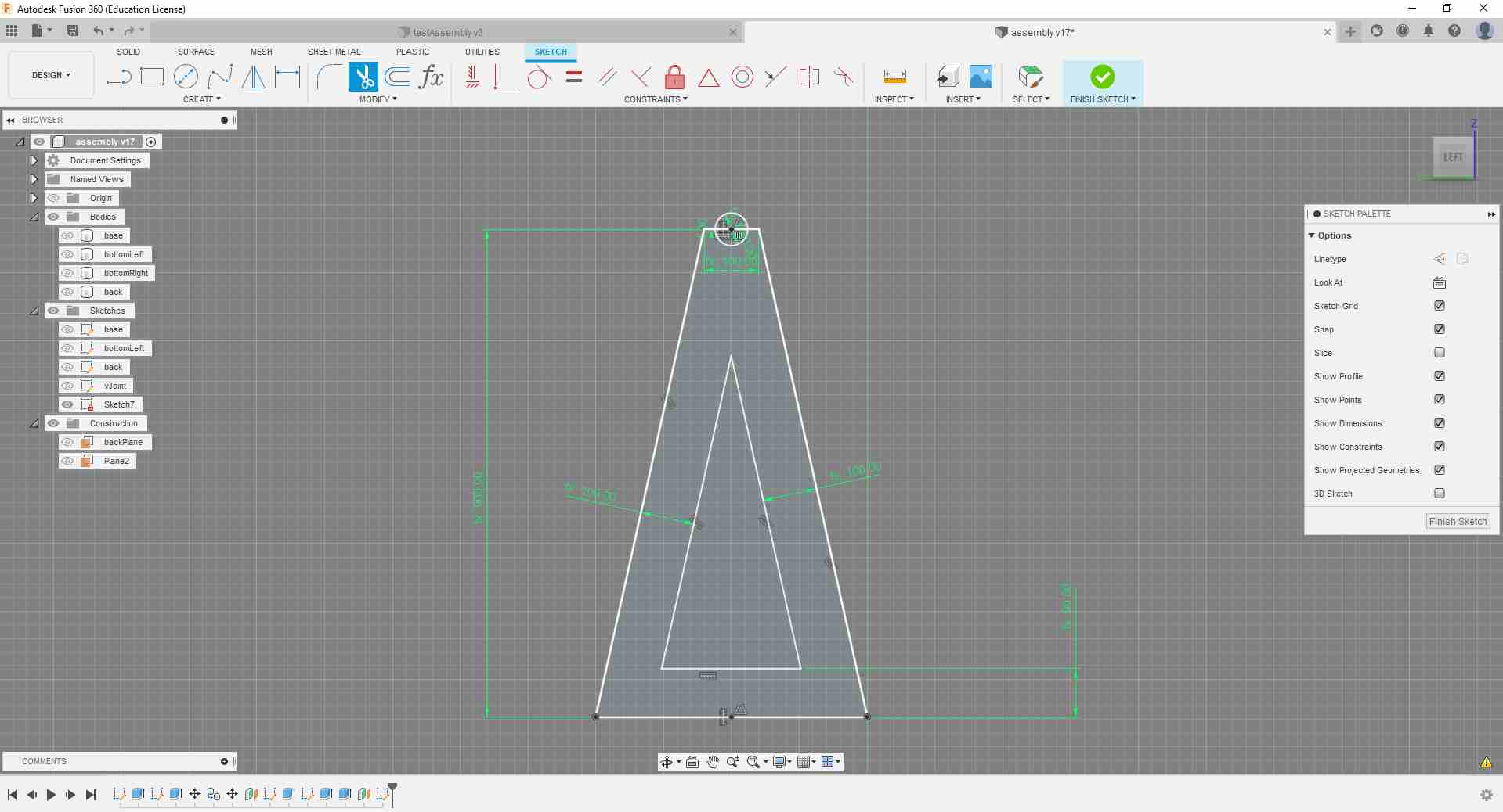
This is to pay homage to the Trim tool which I used heavily this week.
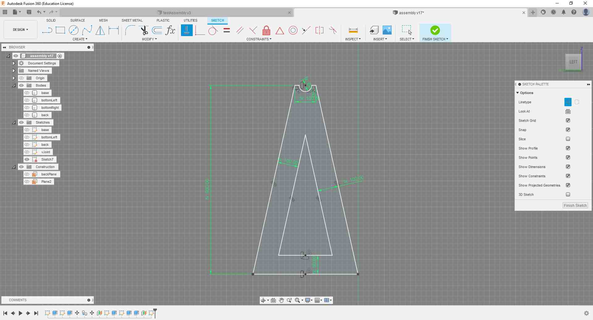
I then extruded the sketch and added the negative pocket to the side where it will be fastened to the bottom panel.
Here is the full design. I used the same trick with copying the top panels.
.jpg)
Next, I wanted to have a quick check whether the designed pieces will fit onto the 4x8 ft wood board, so I copied my bodies and layed them flat and drew a rectangle with the board dimensions around them.
As it turned out, the back piece would never fit in there, so I had to find a solution.
.jpg)
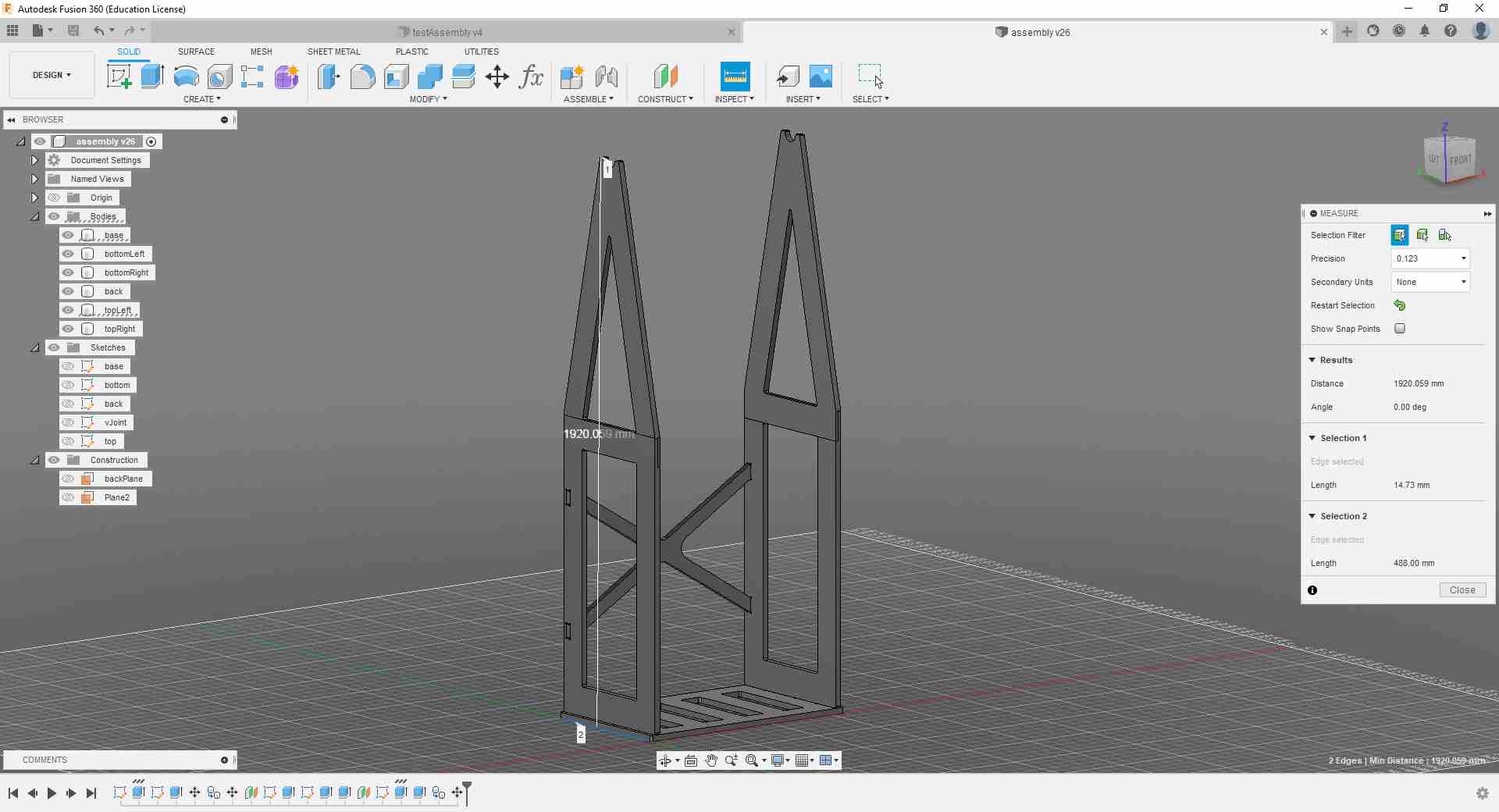
I also used the Inspect measuring tool to do a rough double-check on my design dimensions.
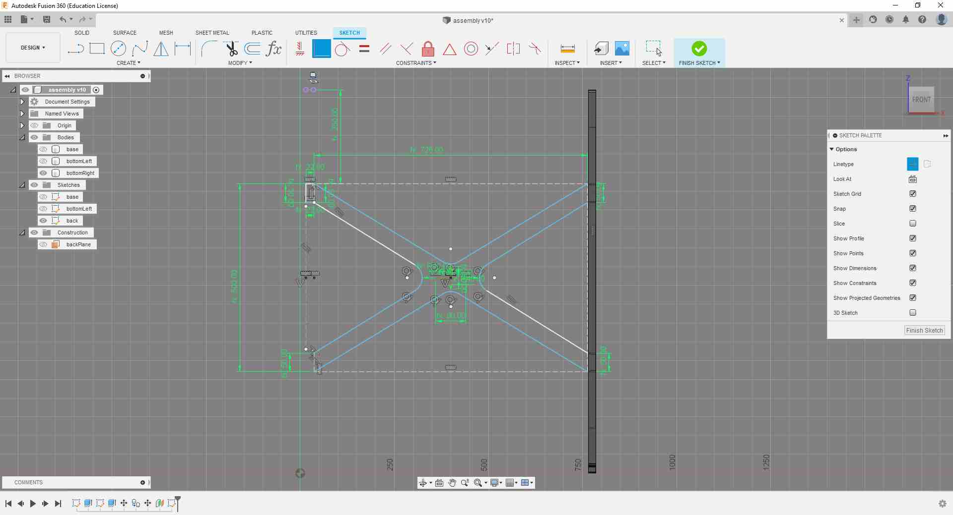
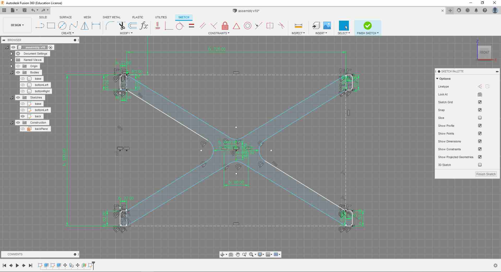
To solve the back piece problem, I decided to redesign the X shape and make it into two joined pieces
To design the joint area, I extruded the legs to the full thickness of the wood board (20 mm), and extruded the joint area to half of that value.
.jpg)
Here are the two new back pieces joined.
.jpg)
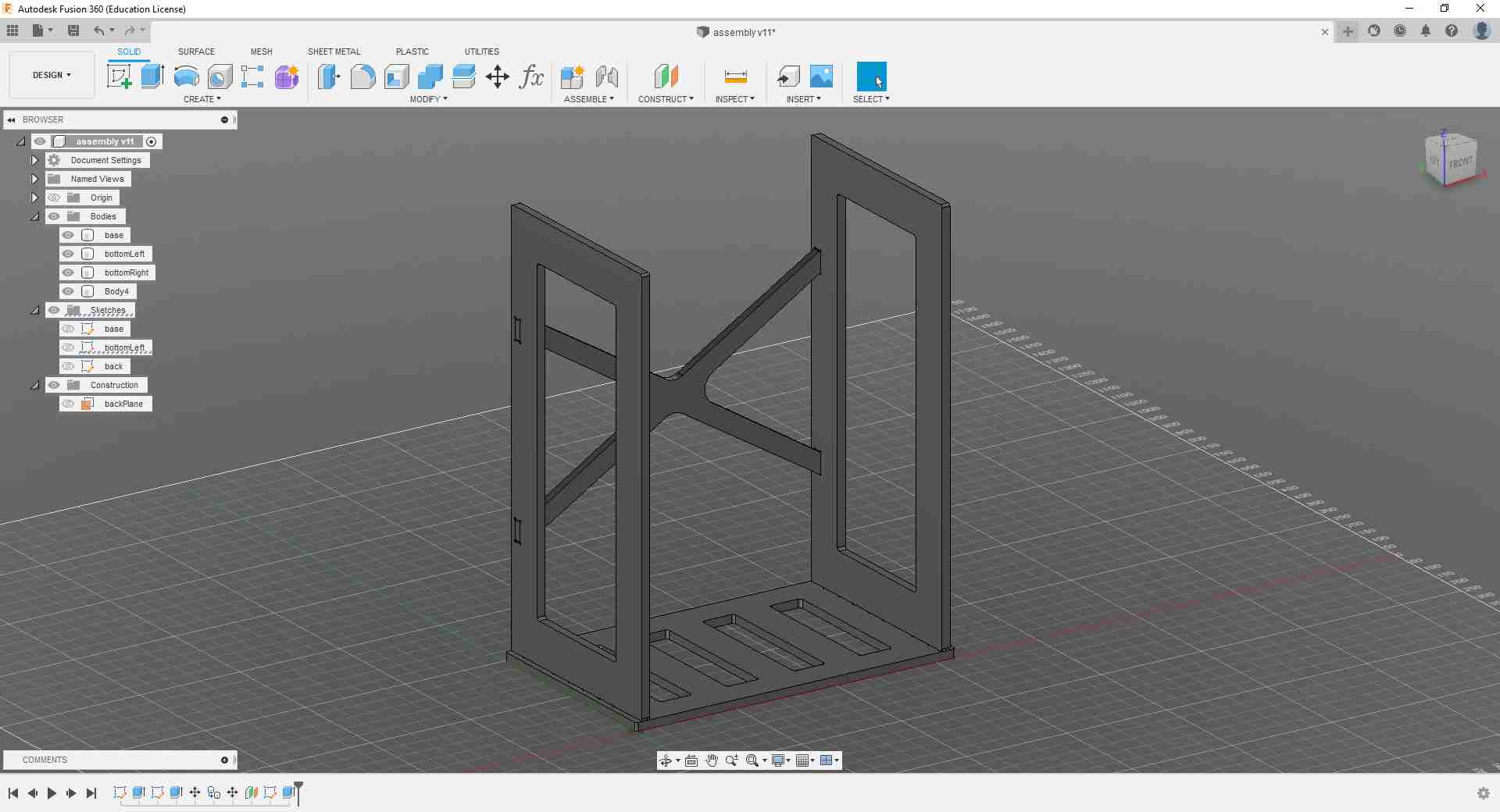
And this is how the rack now looks like.
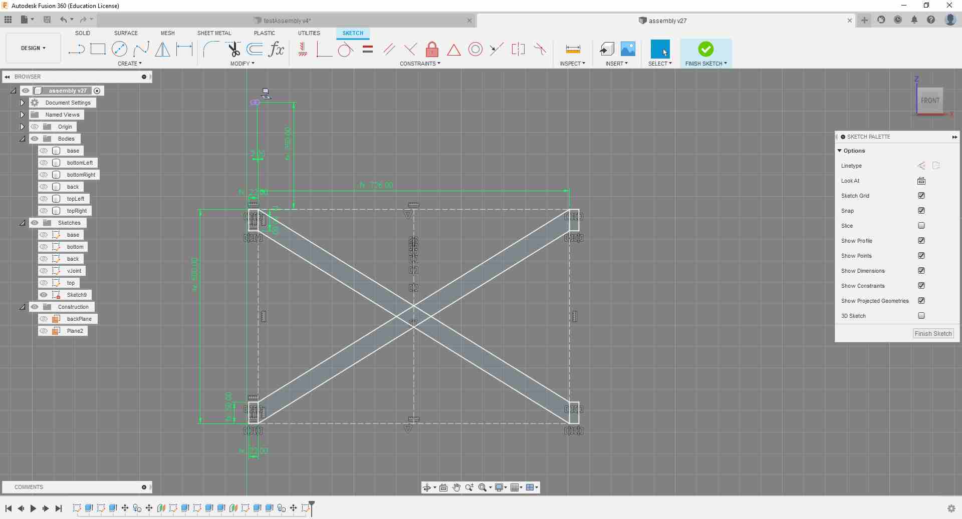
I ran my design by Aaron again, and he noted that my dog bone joints between the side panels and the base panel will not go all the way in because of the fillet curvature of the milling tool. So I either had to make the joint fingers longer, or I could cut more into the side panels like in the picture below. So I decided on that option and changed all of the joint fingers accordingly.
.jpg)
Making the Test Joint
After I was satisfied with my rack model, I had to prepare for machining it. For the first step, I needed to make a test joint to check my clearance parameters to be able to assemble the pieces properly.
To do that quickly I copied my project into a new file, and used the Split Body function to cut out a small piece of my joint area.
.jpg)
.jpg)
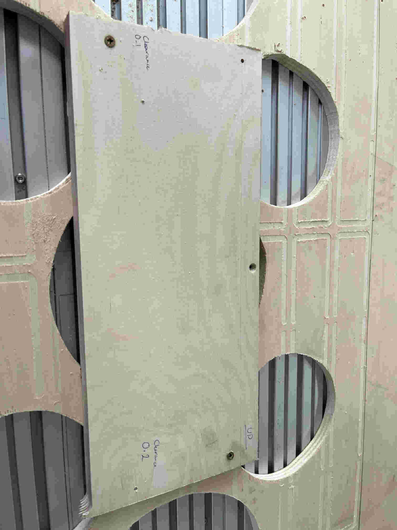
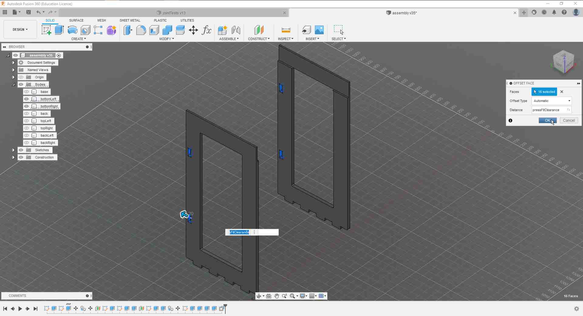
With the pieces cut, I layed them down flat in preparation for milling. On the right I added a clearance of 0.2 mm to each side of the female slot (as denoted by the two circular holes), and a 0.1 mm clearance to the left one.
.jpg)
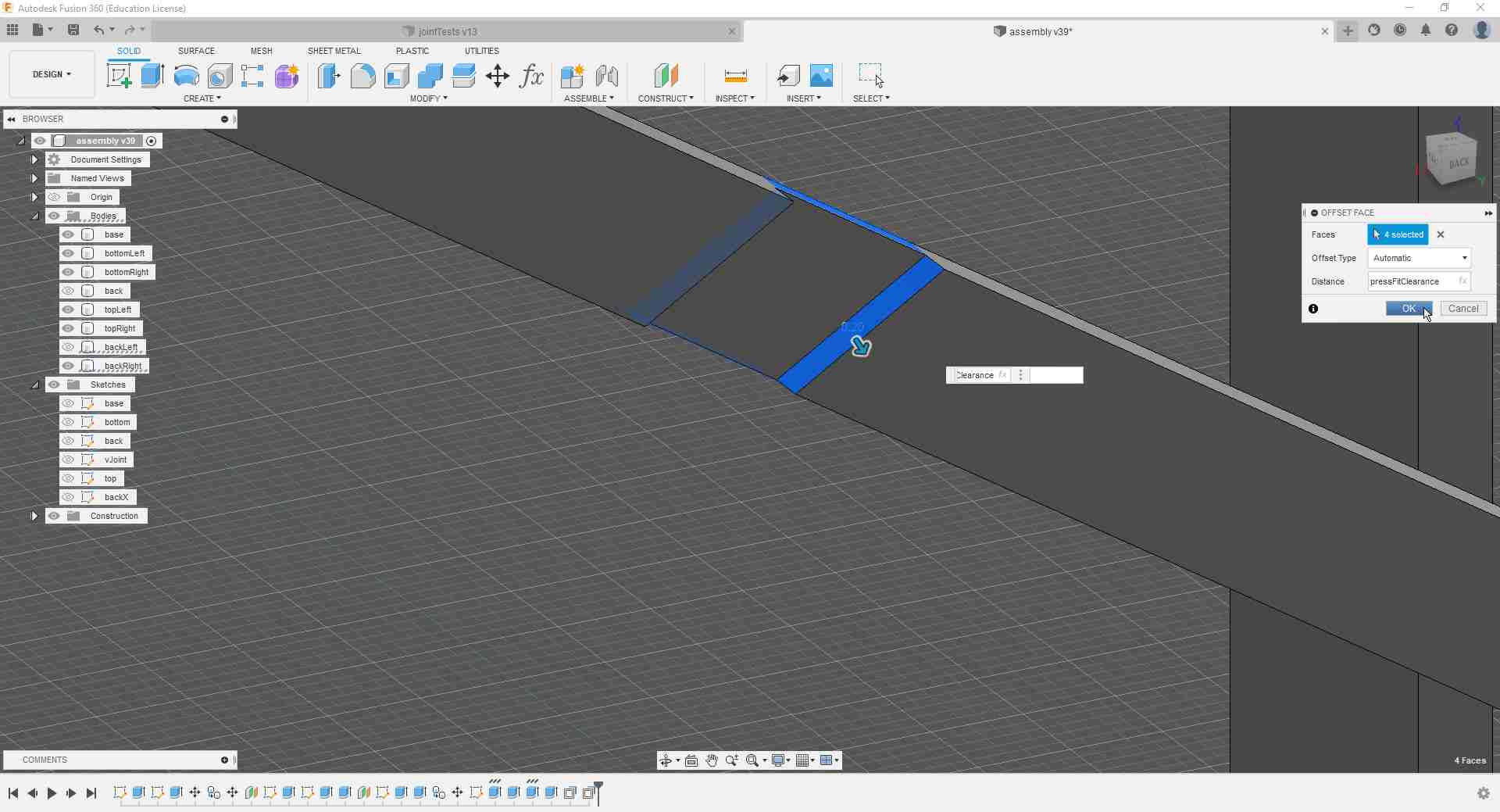
Another conversation with Aaron later, I realized that my dog bone design is wrong since I centered the circular slot on the tips of the slot corners as in the picture above. I either had to make the circle diameter larger so that the tool can get through to the filleted corner, or I had to place my 6 mm circle a bit into the rectangle so that the resulting slot can fit the mill bit. I went with the latter option since it would look better on the manufactured rack.
.jpg)
Since I don't need those circular holes and can just add a scribble on the wood denoting the clearance values, I got rid of them.
.jpg)
Setting Up the CAM in Fusion 360
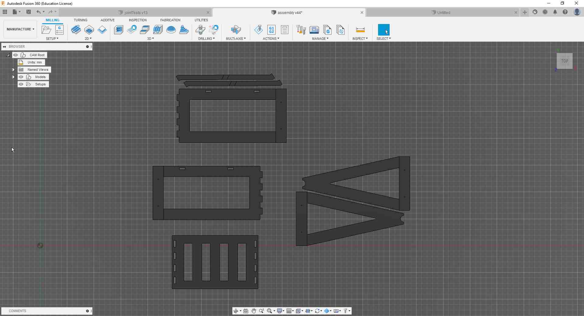
Before I am able to program the manufacturing jobs with the CAM suit in Fusion 360, there was some setting up to be done. To begin with that, I changed into the Manufacture environment.
.jpg)
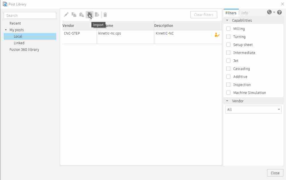
Because I would be working on our CNC machine for the first time, I needed to add the machine profile and other setting files to be able to program a usable G-Code. For that, I got the setup files from our Fablab library and saved them locally on my machine, and then went to the Manage tab and clicked on Post Library. It is very important to note that the order in which I add the files makes a difference, as my lab colleagues had trouble with Fusion 360 whenever they messed up that order.
.jpg)
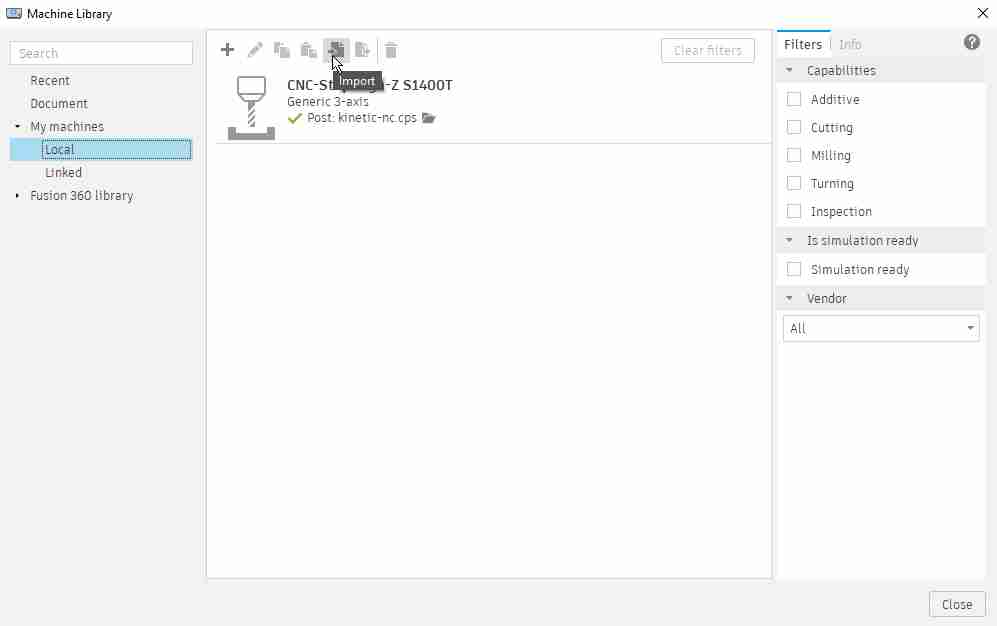
In there, I navigated to My posts > Local and clicked on Import. There I had to direct the software to where I saved the post processor setup file.
After that was done, I went and did the same thing for the machine library.
.jpg)
I had to navigate to the locally saved machines and import the machine setup file from my local directory.
And then the last step follows the exact procedure but for the Tool Library.
.jpg)
Preparing the Test Joint CAM
After all the appropriate settings got imported, it was time for preparing my first gcode. To do that I went to the Setup tab and clicked on New Setup.
.jpg)
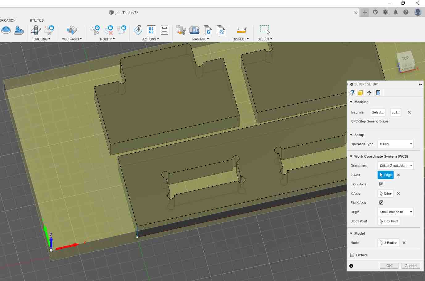
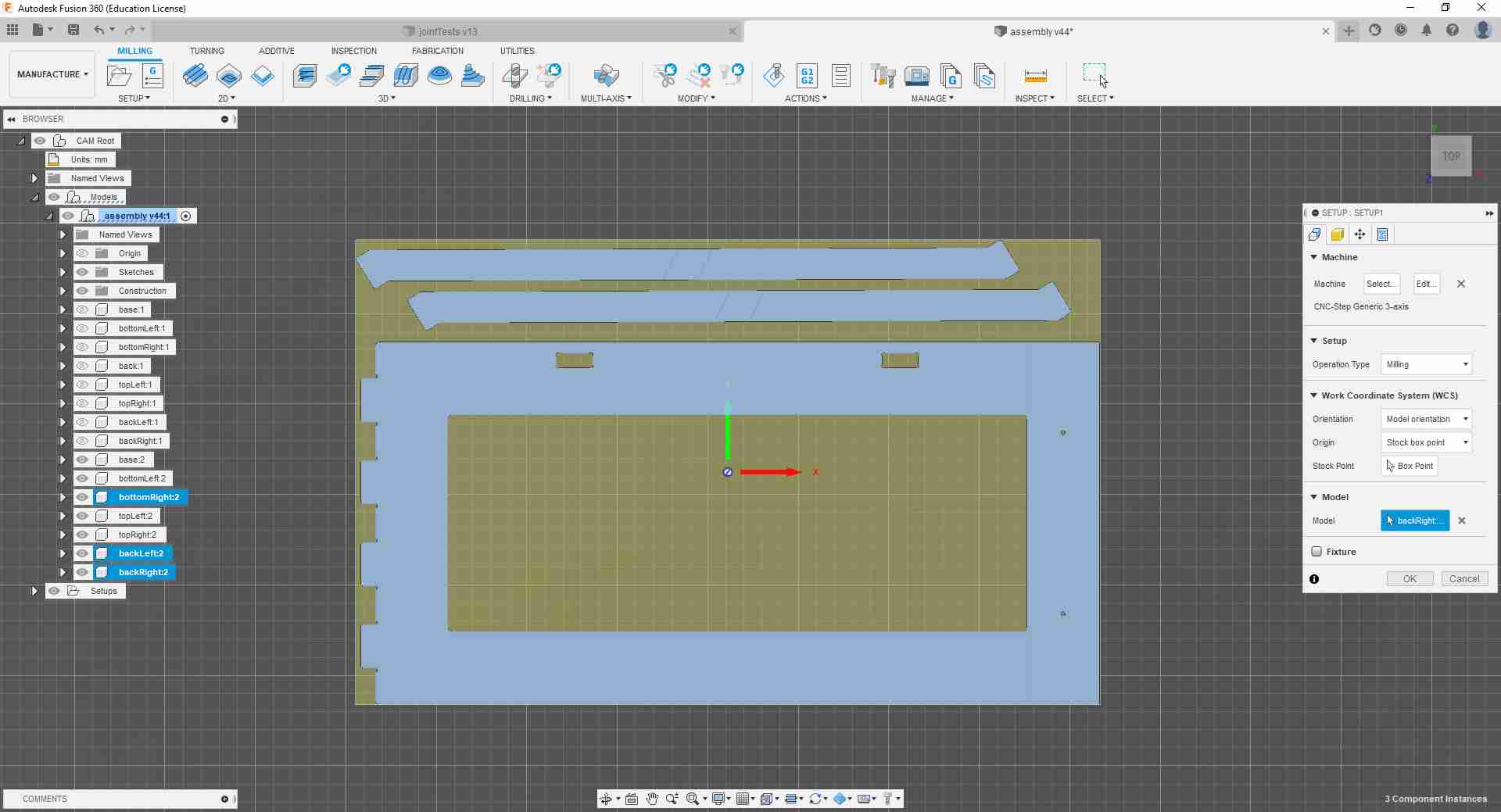
In the first tab, I added the machine I just imported and told the software the location and orientation of my origin and added which components I wanted to include in the setup.
In the second tab, I added the dimensions of the stock material I would be using. For that, I chose the Fixed size box option and added the dimensions manually.
.jpg)
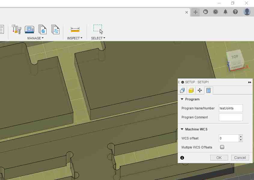
I then skipped to the fourth tab and just changed the Program Name/Number to a name of my choice. In the third tab I skipped, I could have specified where my physical fixtures are so that the manufacturing tool avoids them when jogging between operations. I did not need that setting because my stock piece will be big enough to clamp far away from the milling area.
As I have mentioned earlier, I also needed to go back to the Design environment to change the dog bone features of my test joint.
.jpg)
.jpg)
Back in the Manufacture environment, I went ahead and selected 2D Contour to perform my first milling operation. It is recommended to mill out internal details and then cut out the outer contours so that the workpiece stays properly fastened during the milling and drilling operations.
.jpg)
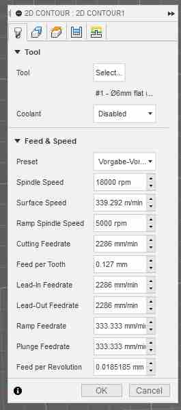
In the menu, I started by selecting the tool from the local library tools I just imported, and then skimmed through the cutting settings just to make sure everything makes sense and is as it should be.
.jpg)
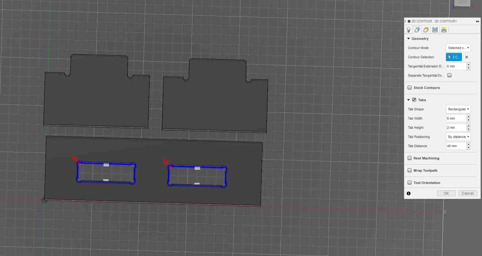
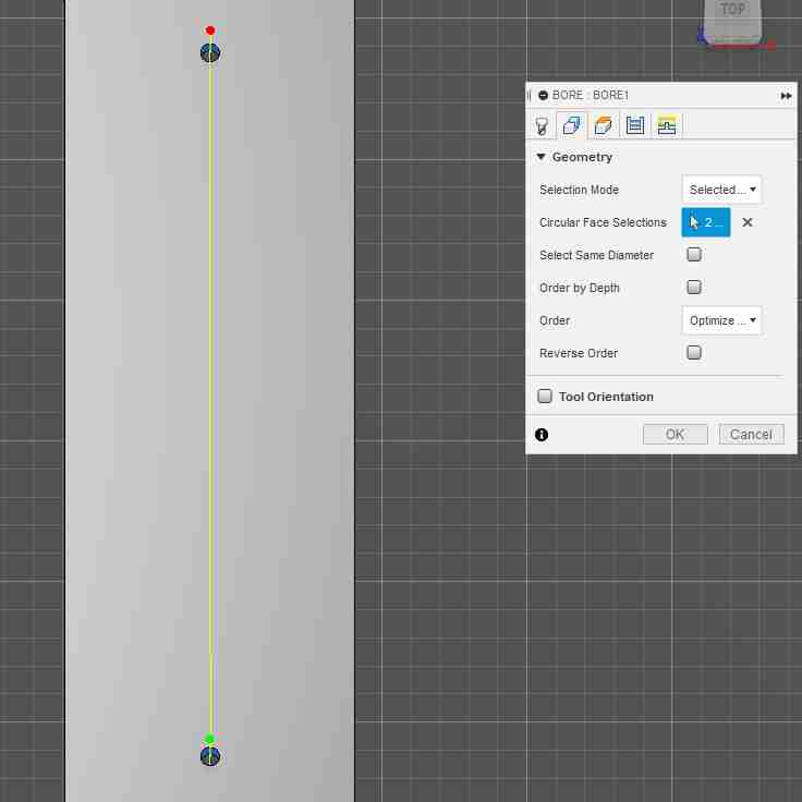
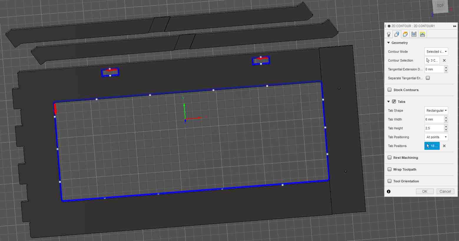
In the next tab, I selected the dog bone contours to mill out first. For that, it was useful to select the bottom contour instead of the top one because when I later added the tabs, I found out that they get attached to the workpiece at the height of the selected contour. And since I want the tabs to be at the bottom, I selected the bottom contour.
It is also important to note that adding tabs is part of the safety procedure we were recommended to follow. That is because completely detached pieces can go flying once hit by the rotating tool and cause injuries and/or damages to the surrounding persons and equipment.
Another thing worth noting is that Fusion 360 has very nicely documented explanations and recommendations about most of its functions. So whenever I was in doubt about what a function meant, I hovered over its input field and read those descriptions.
.jpg)
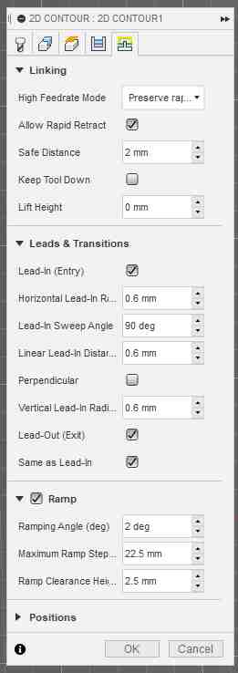
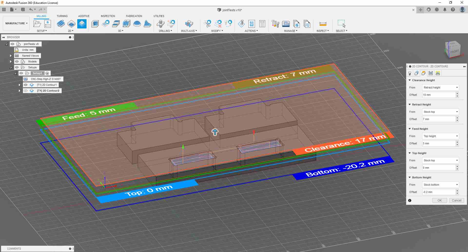
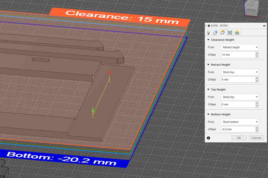
On to the next tab, I adjusted the working heights for the tool and made sure that all safety clearances are adhered to, but also that those clearance heights made sense because if they are set too high, that would add substantial manufacturing time to the job. This happens because the jogging speed within these heights is slowed down to a safe speed.
.jpg)
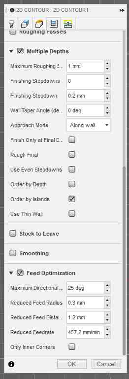
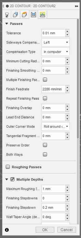
In the tab afterwards, I left the passes settings as they are, but activated the Multiple Depths function so that the tool reaches the desired final depth gradually and not directly plunge into the stock material.
Some notes in hindsight, I could have activated the Both Ways option in Passes so that the tool mills in both travel directions to save time. I also should have increased the step depth in the Multiple Depths settings, since that value can lie between 40-100% of tool diameter, which is 6 mm for this job.
.jpg)
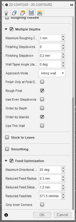
For experimentation purposes, I also activated Feed Optimization that slows down feedrate when the tool changes direction. I did that after my Fab-colleagues mentioned that the tool was overshooting around corners that they had to slow down the feedrate mid-job to compensate for that. In hindsight, the Reduced Feedrate could have been set higher as it slowed down too much compared to the normal feedrate.
So after compensating for the overshooting around corners, I went back and set the tool feeds and speeds to the full setting since I had them reduced before I started to account for the tool behavior.
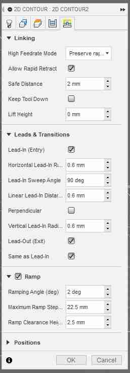
In the last tab, I activated the Ramp option which in hindsight is a good feature but unnecessary when cutting our wood jobs.
This is how the finished job would look like.
.jpg)
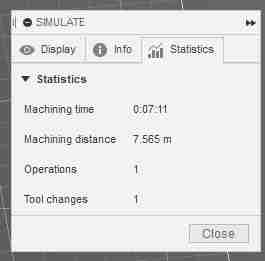
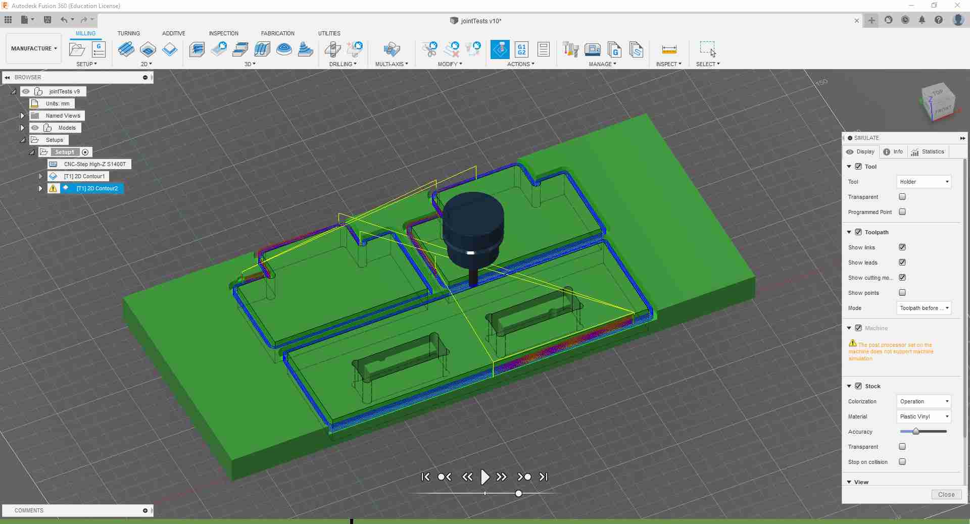
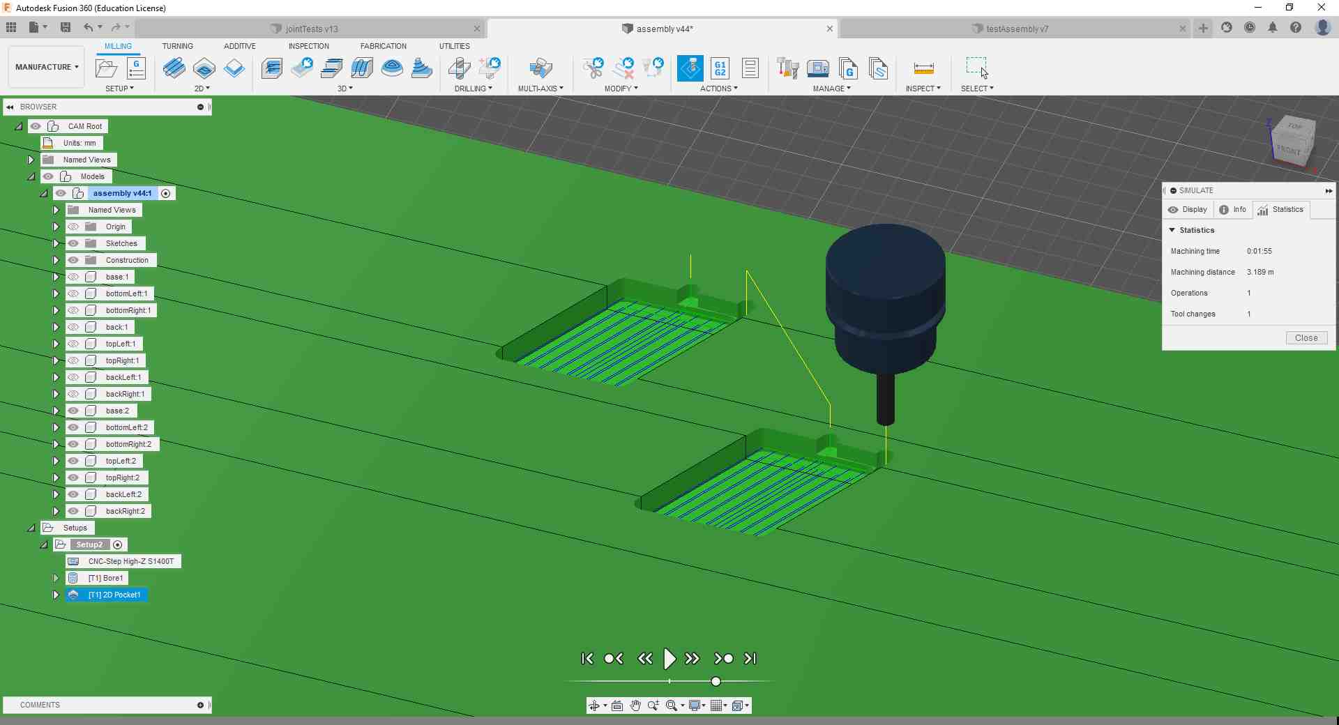
Following the recommendation of our local instructor, I went ahead and simulated the milling job and watched the full process making sure the job sequence is acceptable and that there are no collisions between the stock piece and the tool unit.
.jpg)
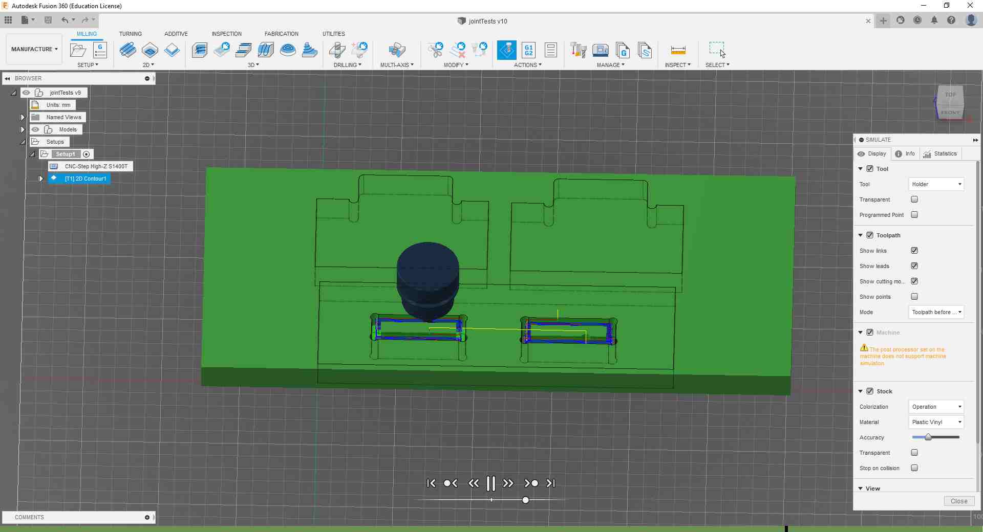
And I made sure to look into the Info and Statistics tab for the machining information.
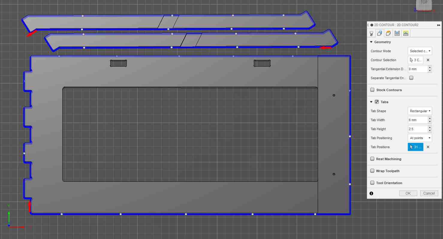
After I was done with that job, I added another 2D Contour operation to cut out the pieces from the stock piece. I also made sure to select the bottom contour as before and added tabs for keeping the pieces from moving.
.jpg)
I then set the heights so that the bottom height is below the stock piece so that the tool cuts out the pieces completely.
In the Passes tab I also activated the Multiple Depths and Feed Optimization options as before.
And here again I activated the Ramp feature.
After finishing the setup, I received the warning message notifying me that some contours were not machined, but I did not need to worry about that since the warning is probably due to the parts being close to the stock edges.
.jpg)
.jpg)
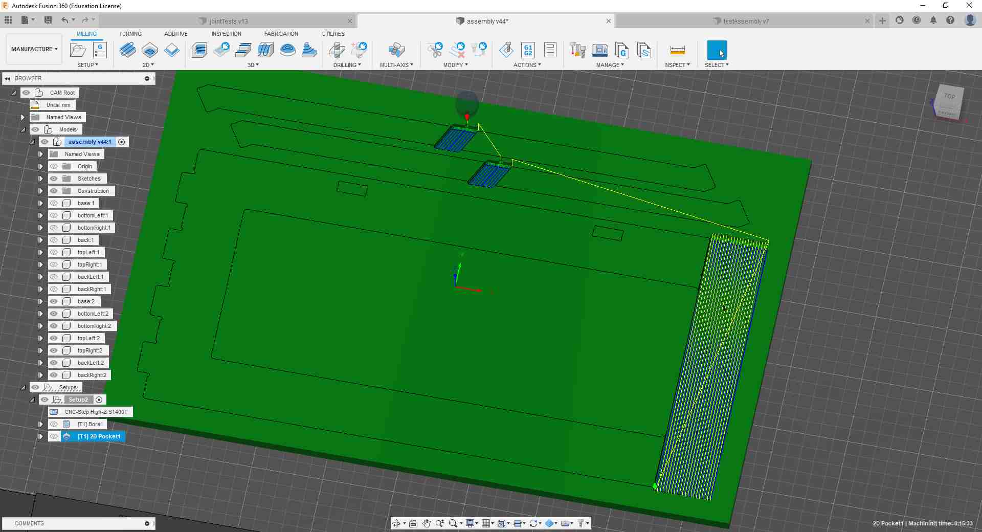
I then double-checked everything again by watching the contour simulation.
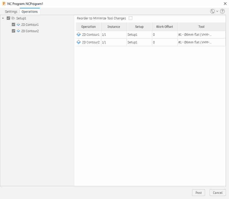
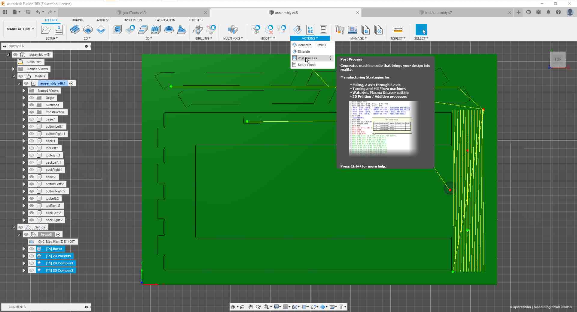
Satisfied with it, I selected both milling operations and went to Actions > Post Process to generate the gcode.
.jpg)
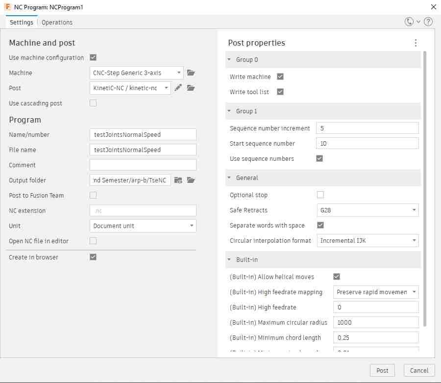
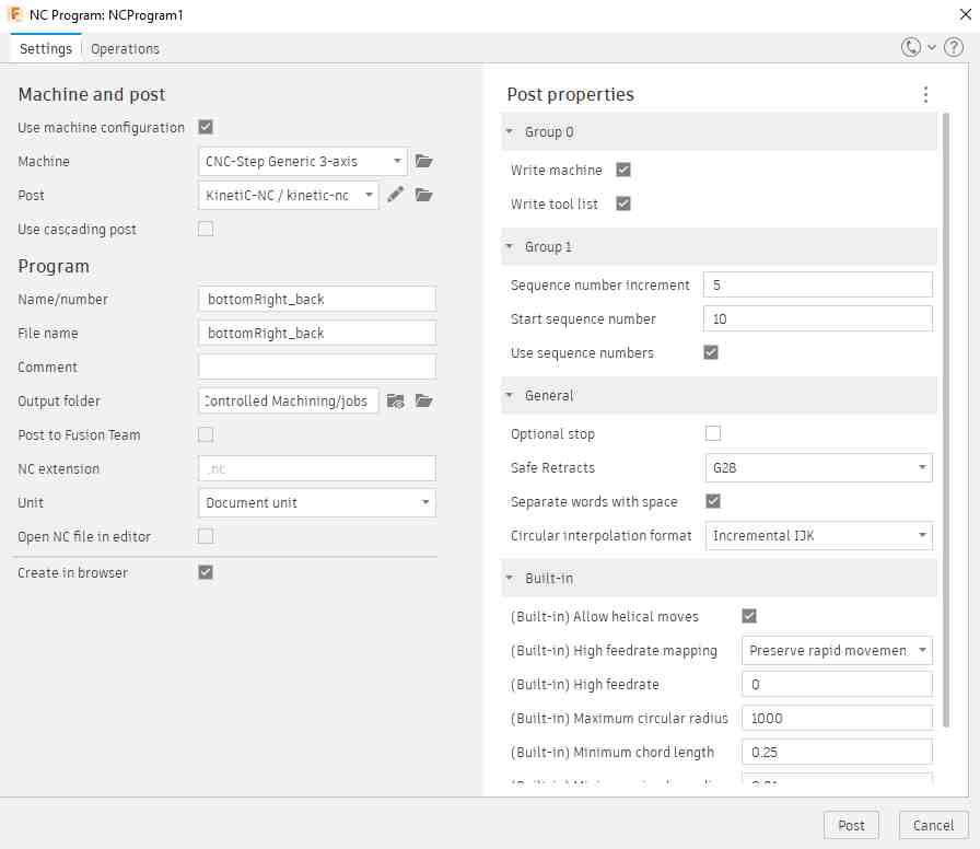
In there I specified the location where the gcode file should be saved, and checked that all information matches our machine's setup.
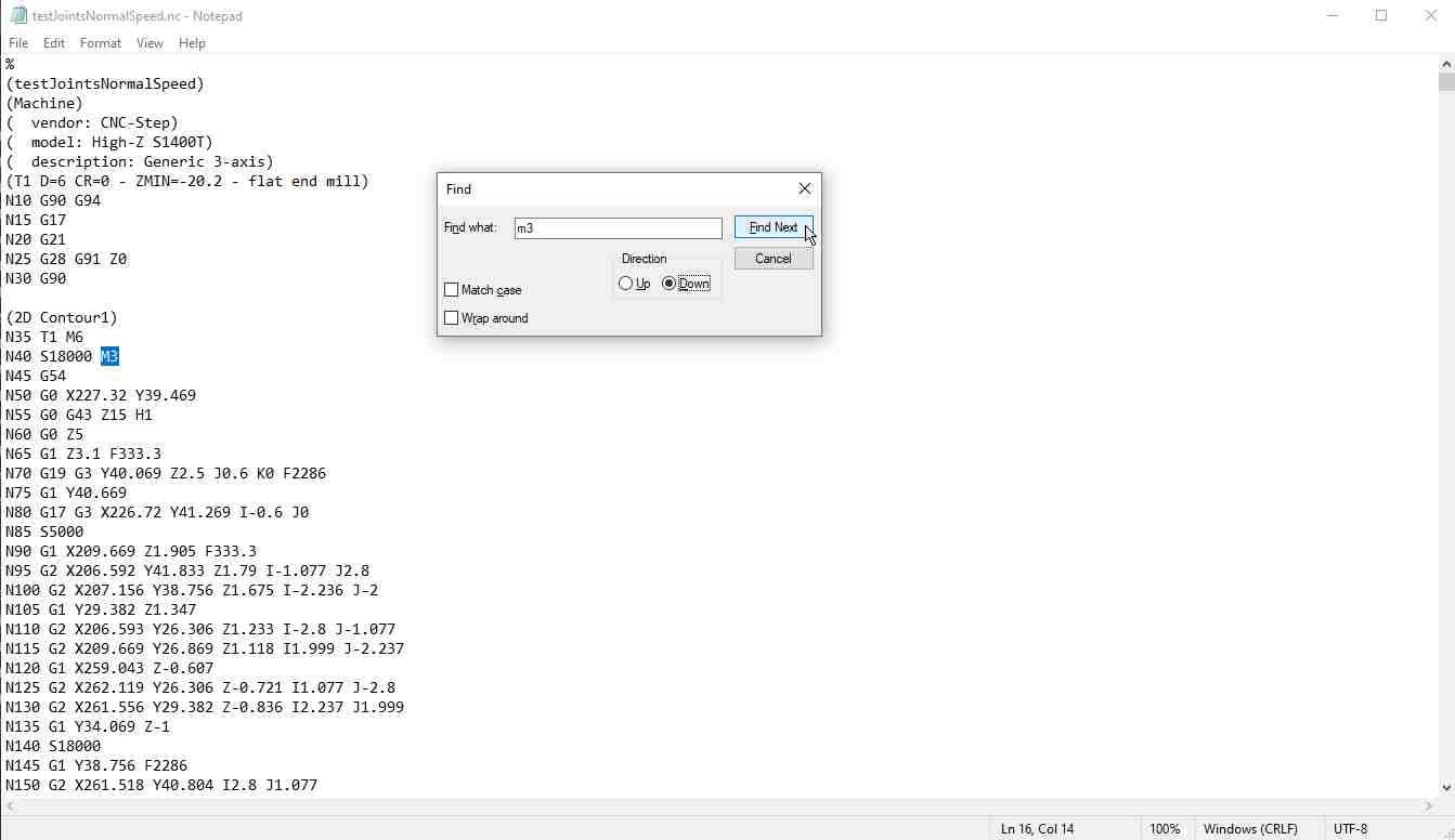
I then opened the gcode file in Notepad and made sure that the M3 command appears only once since Aaron had warned me about it causing trouble otherwise.
It was then time to simulate the gcode again using Nc Viewer since our post processor sometimes adds suicidal lines when saving the file.
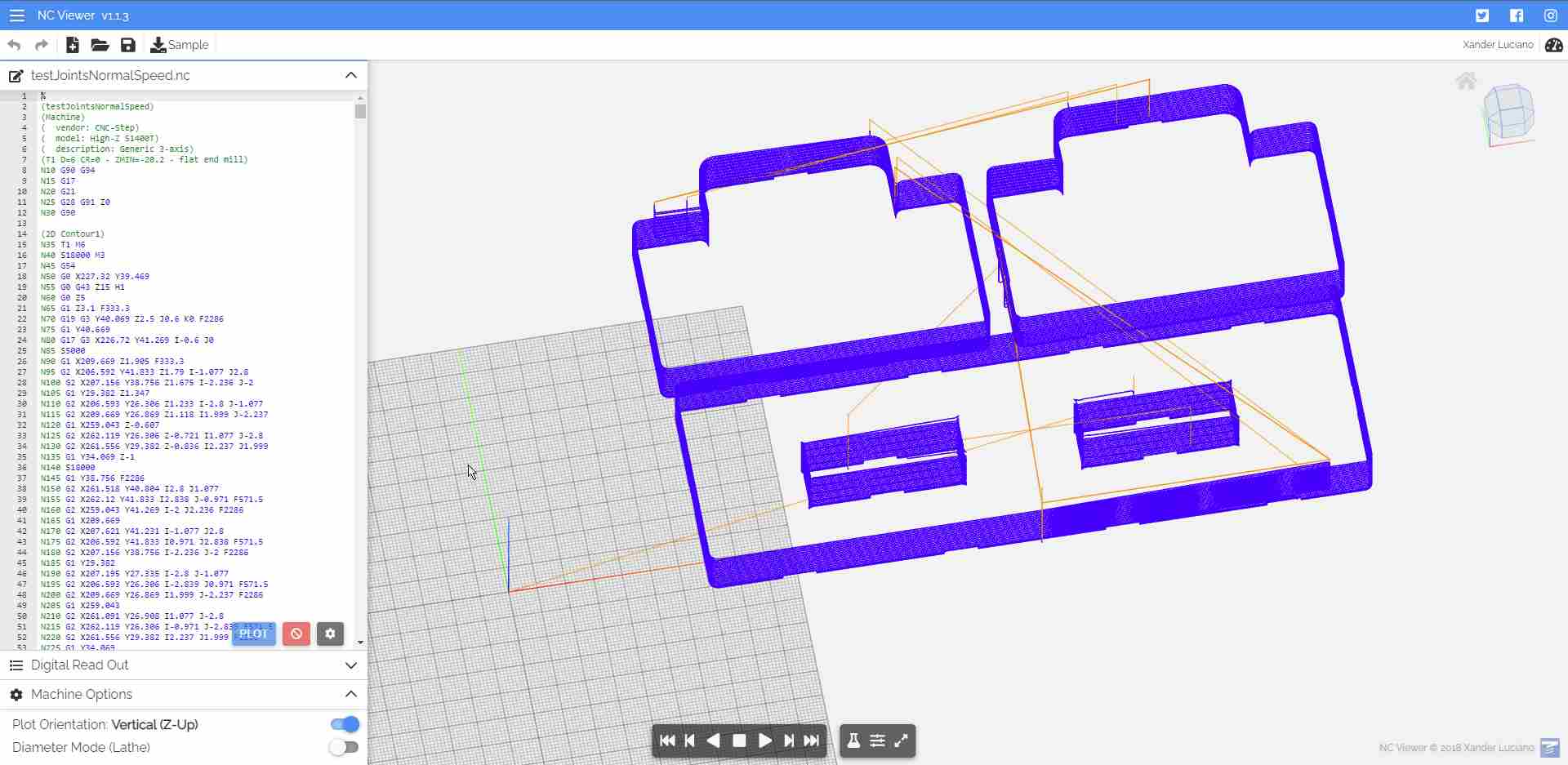
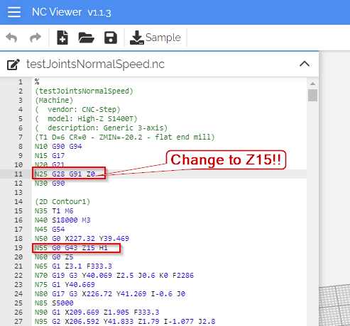
That's when I noticed I need to edit the first Z command so that the machine does not crash through the stock piece.
Milling the Test Joint
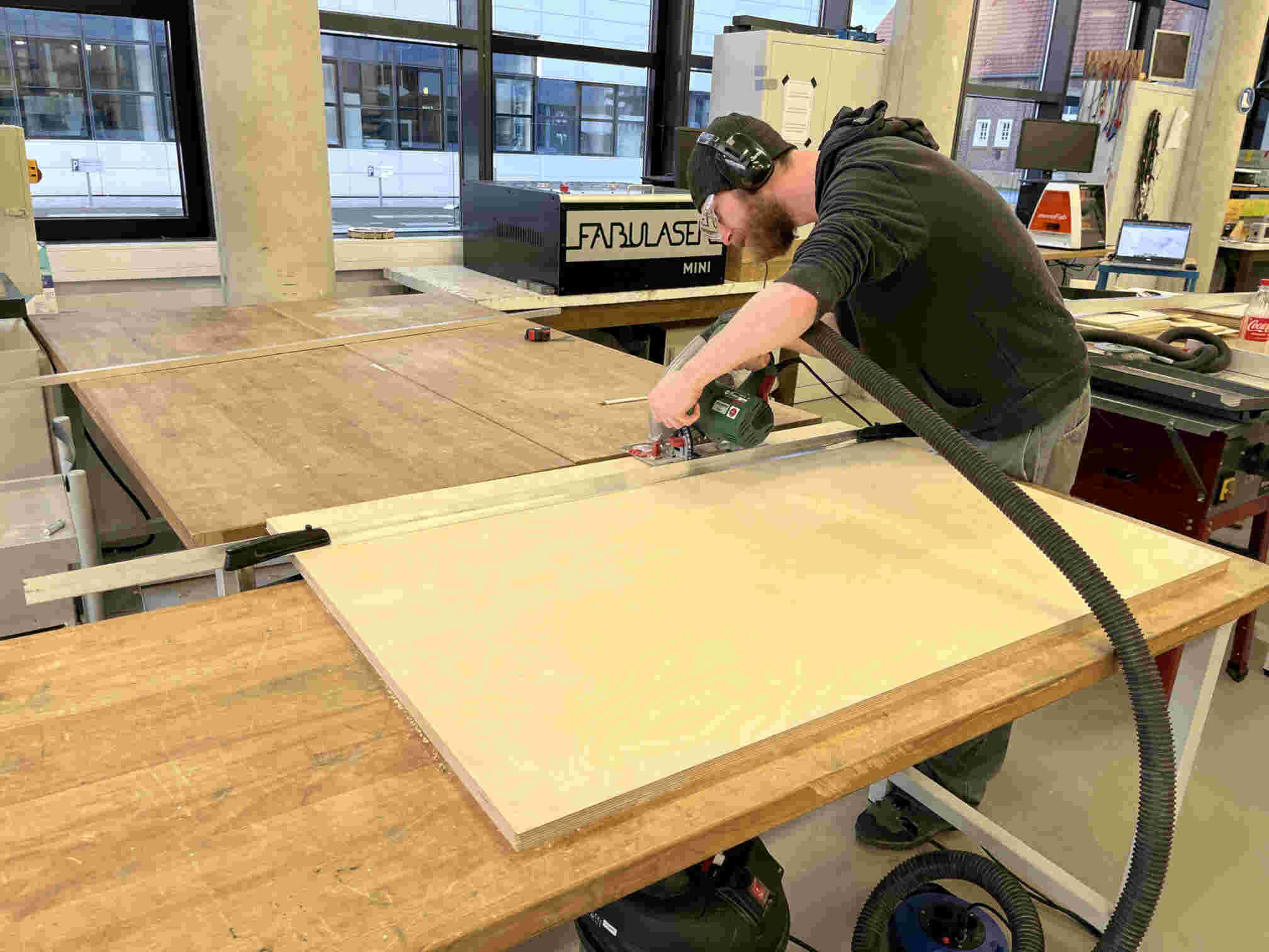
After all files were prepared for milling, I enlisted Aaron's help to cut me a small piece of plywood to use.
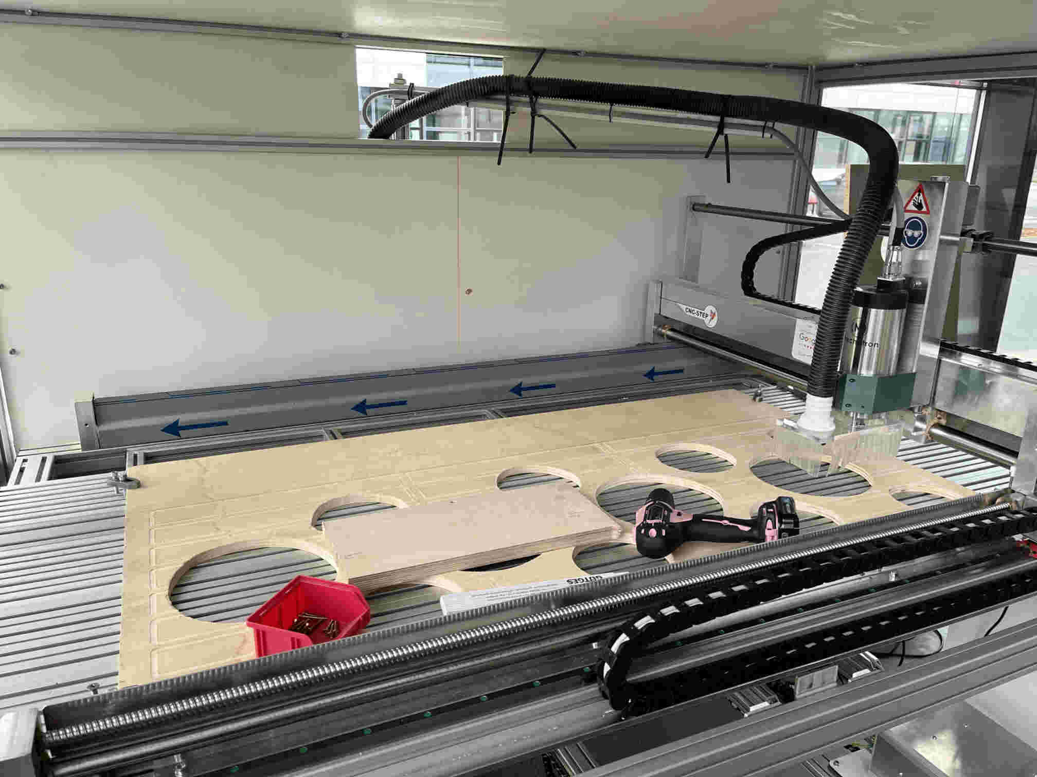
I then fastened down a sacrificial piece of wood to put my stock on.
And then screwed the stock piece on top.
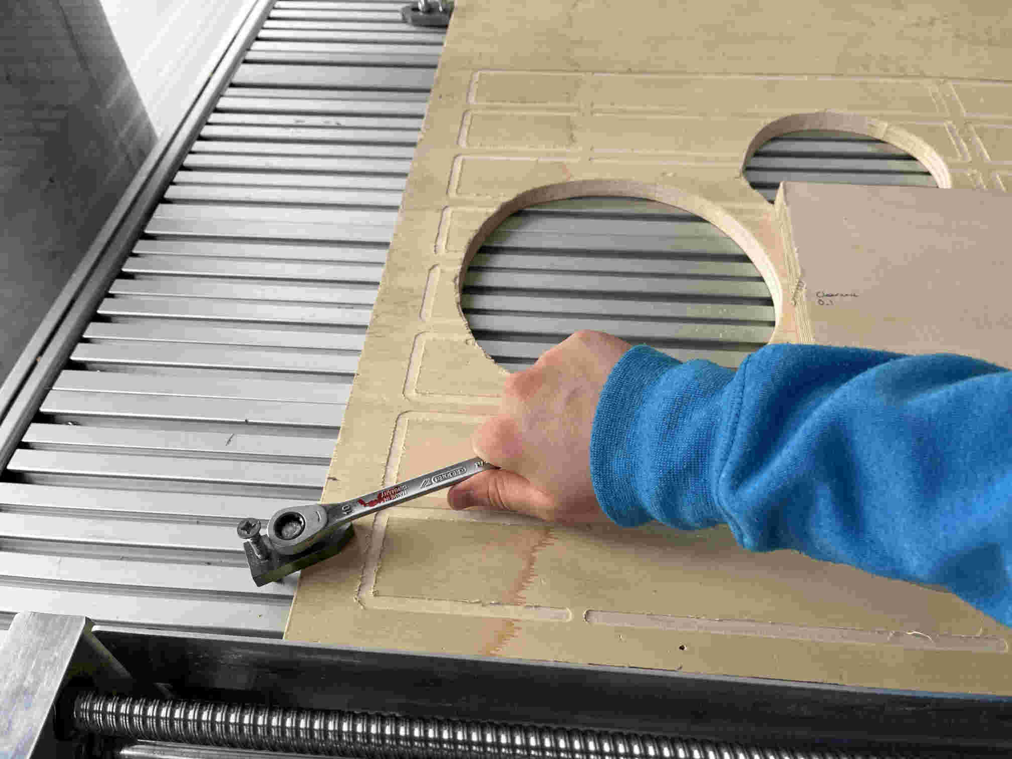
I made sure to scribble down which side of the joint has which clearance.
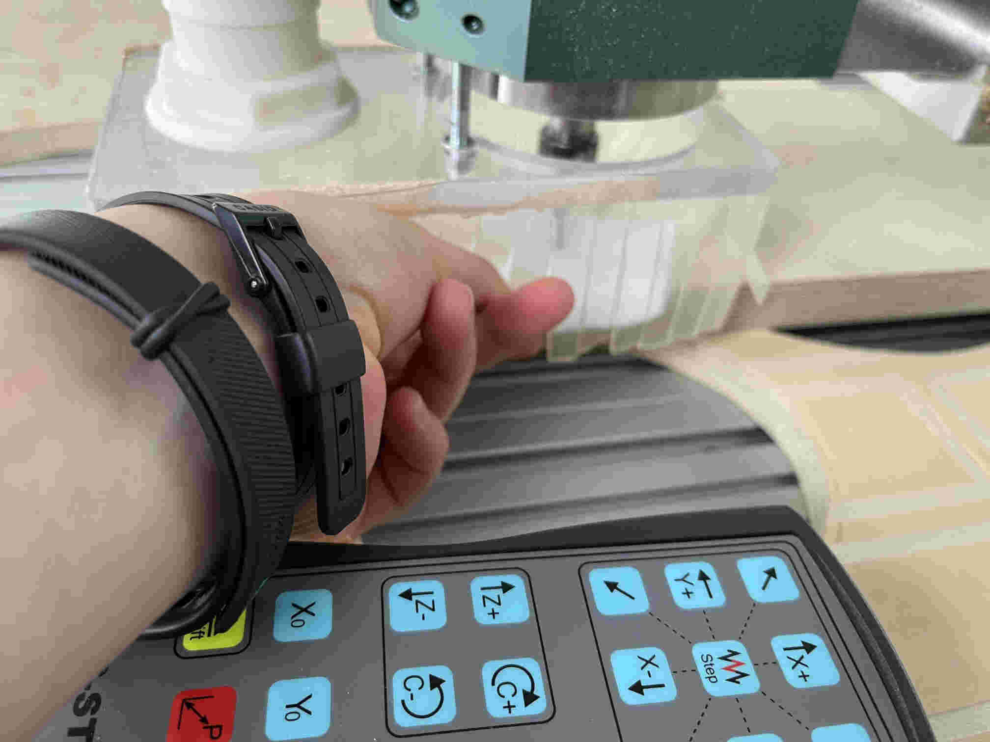
And then it was time to set the zero of the job and save it in G54.
I jogged the machine to the lower left corner and called it my X and Y zeros.
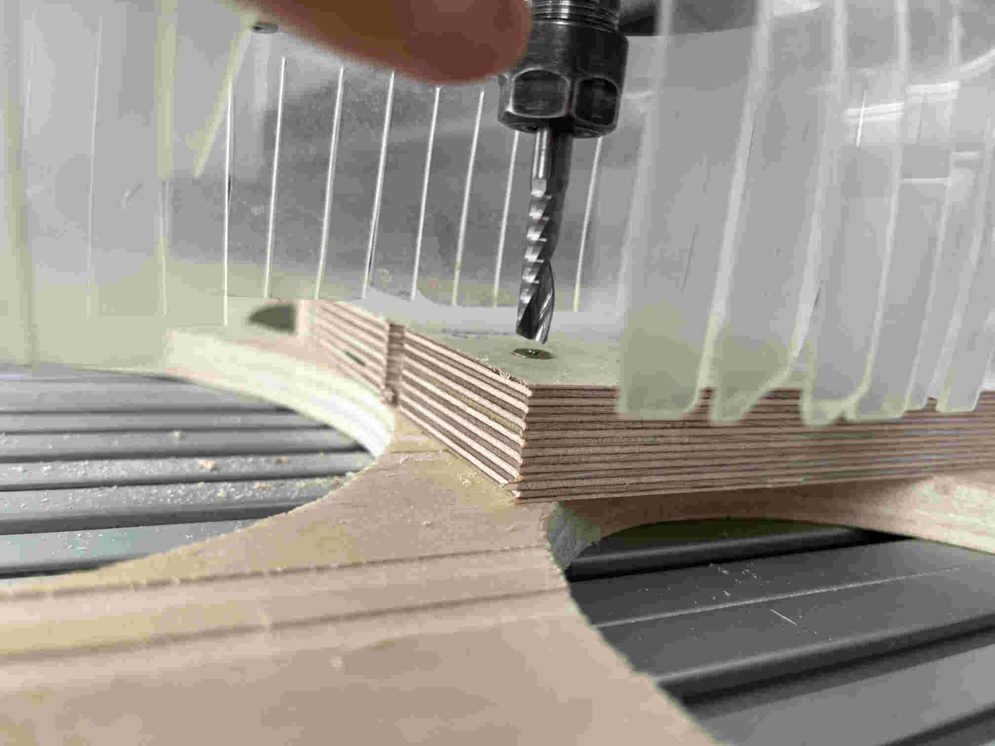
And then jogged it to somewhere on top of the stock, and carefully lowered the z-axis until the piece of paper I was holding between the mill bit and the stock was harder to move around. That was my Z zero.
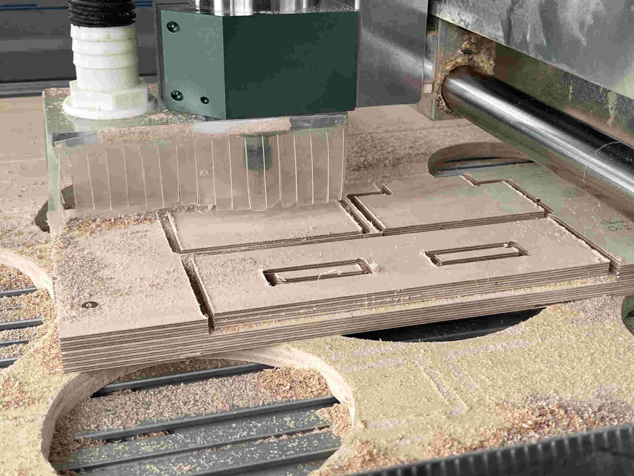
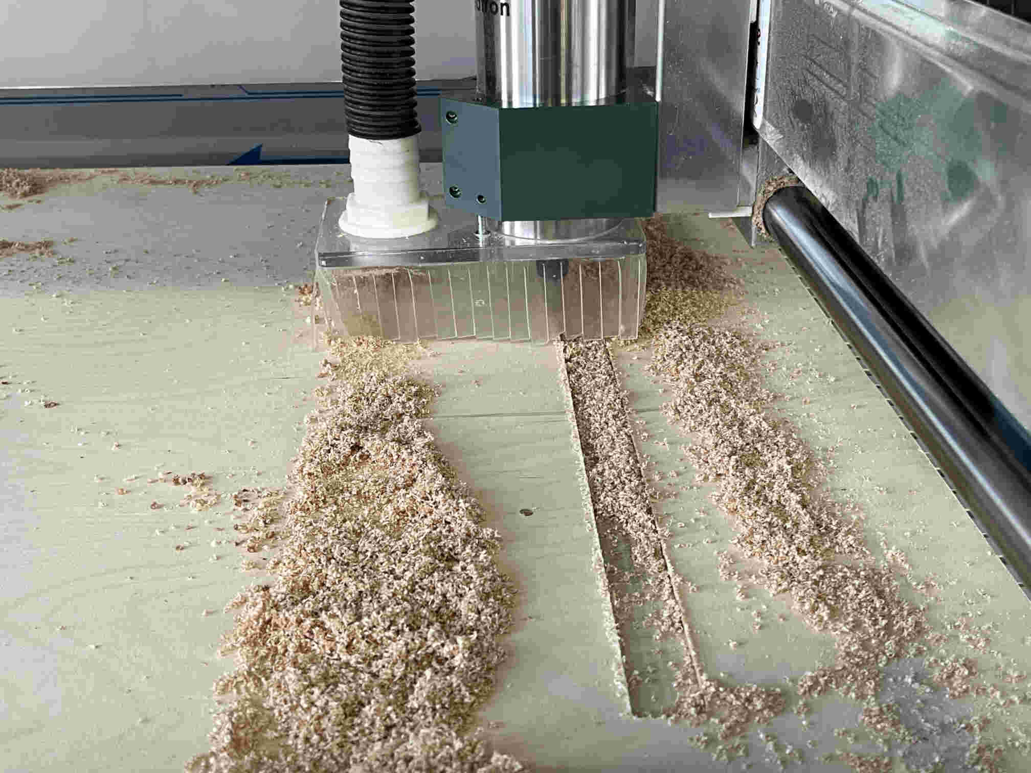
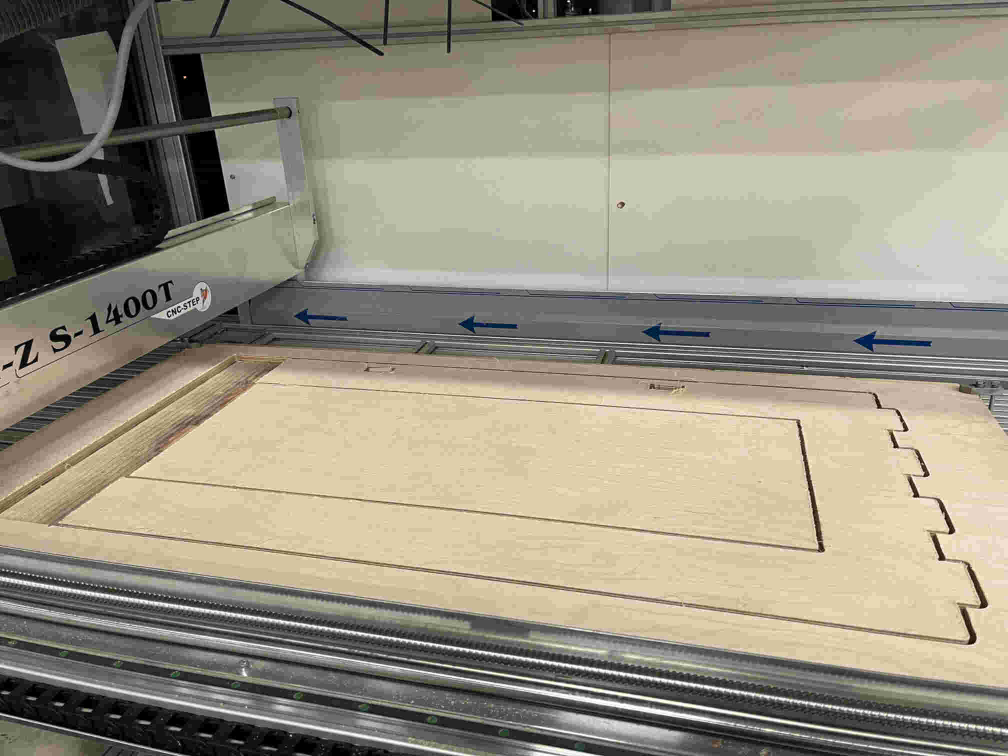
Ready to start the job, I turned on the dust extraction vacuum cleaner...
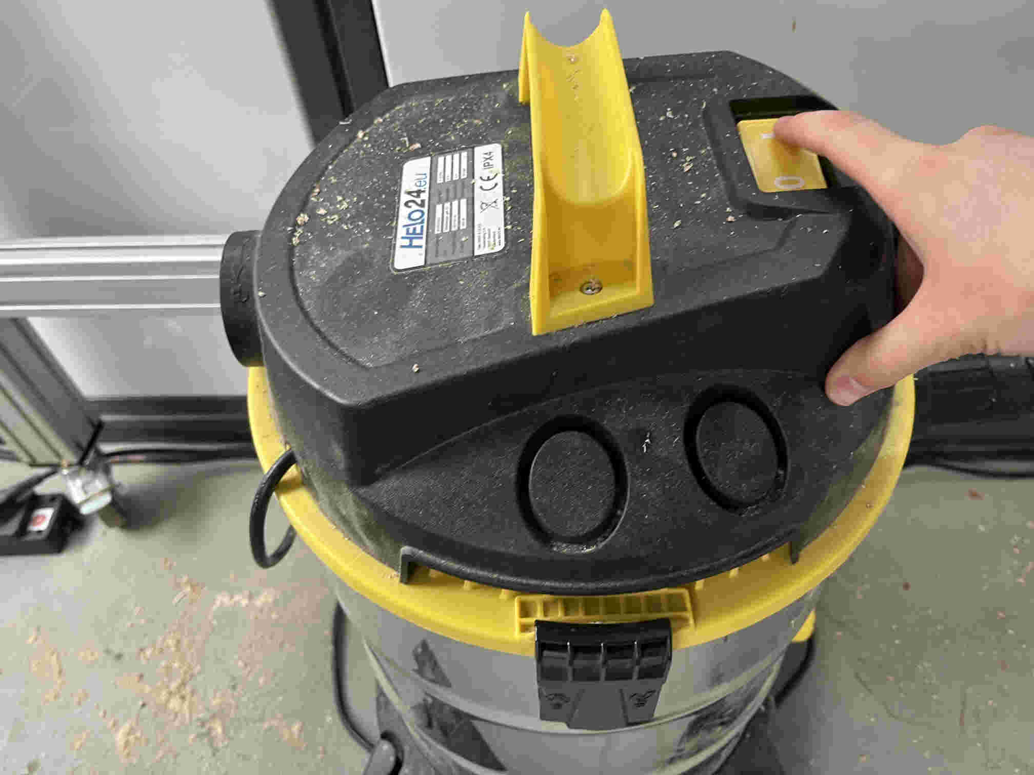
...and pressed Start the actual program.
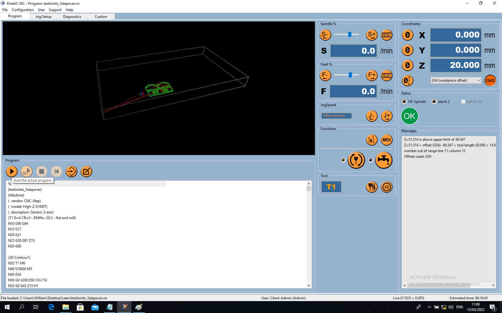
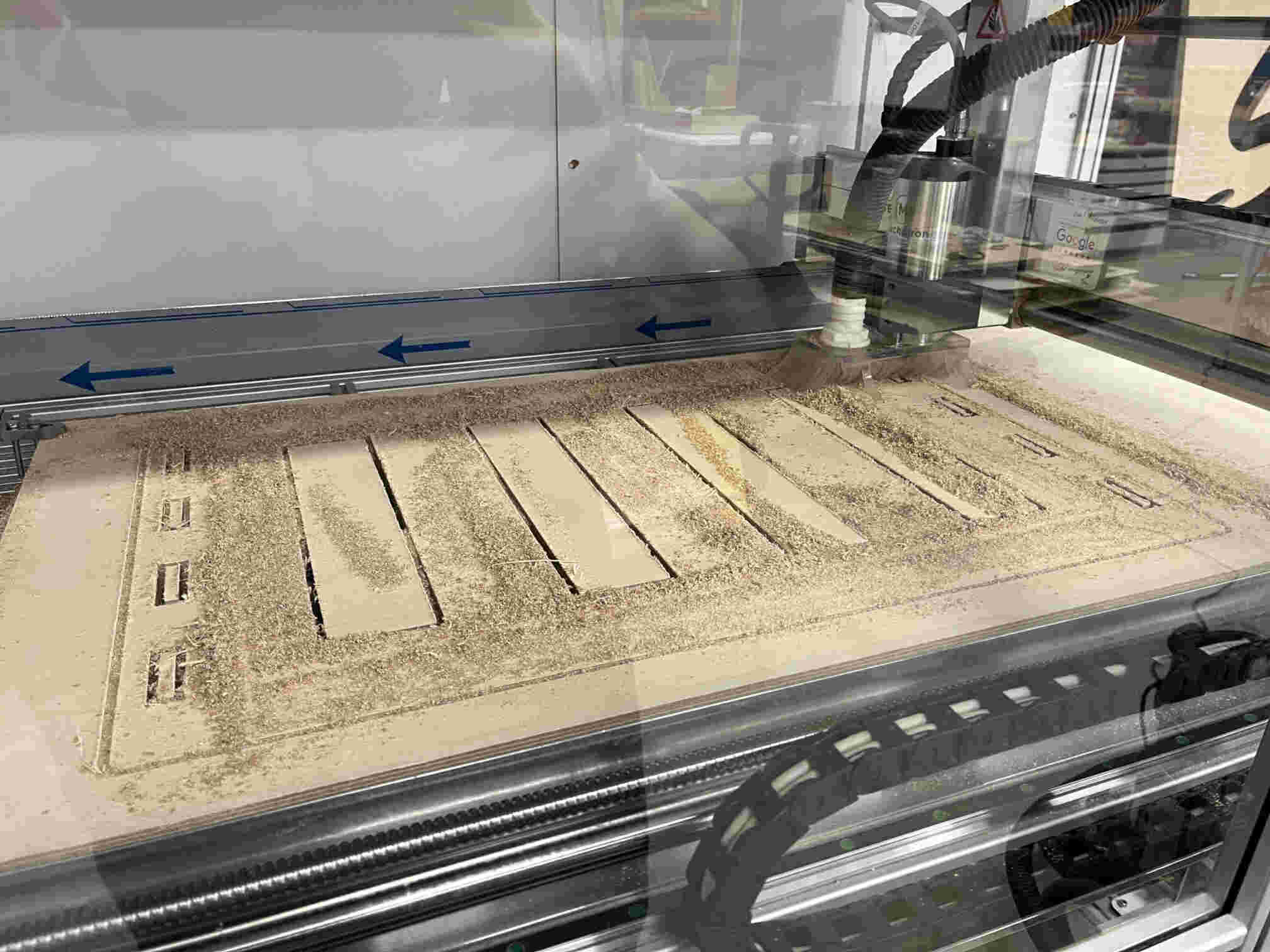
Everything looking good so far.
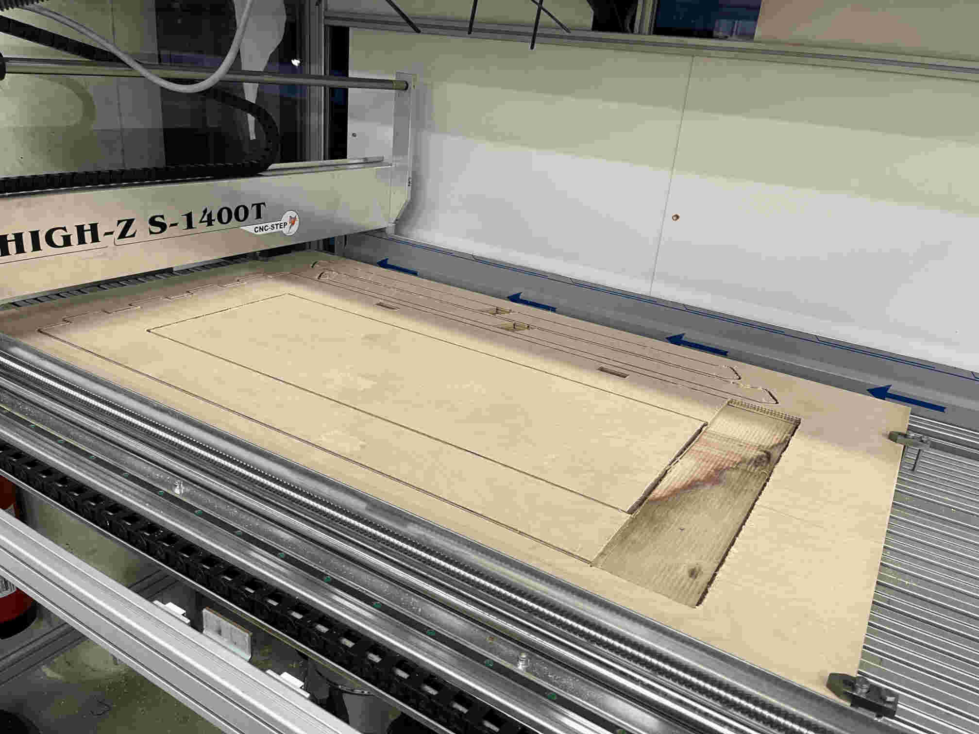
Done!
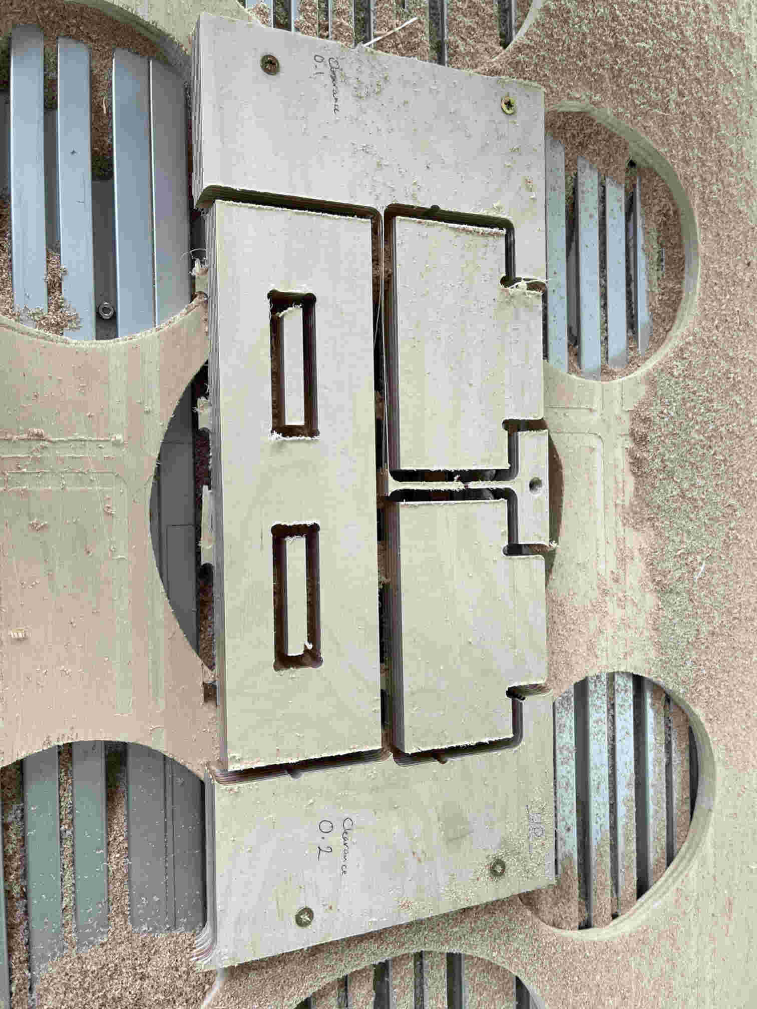
I broke off the test joint off the stock and tested the clearance fit, which resulted in a better fit at 0.2 mm clearance.
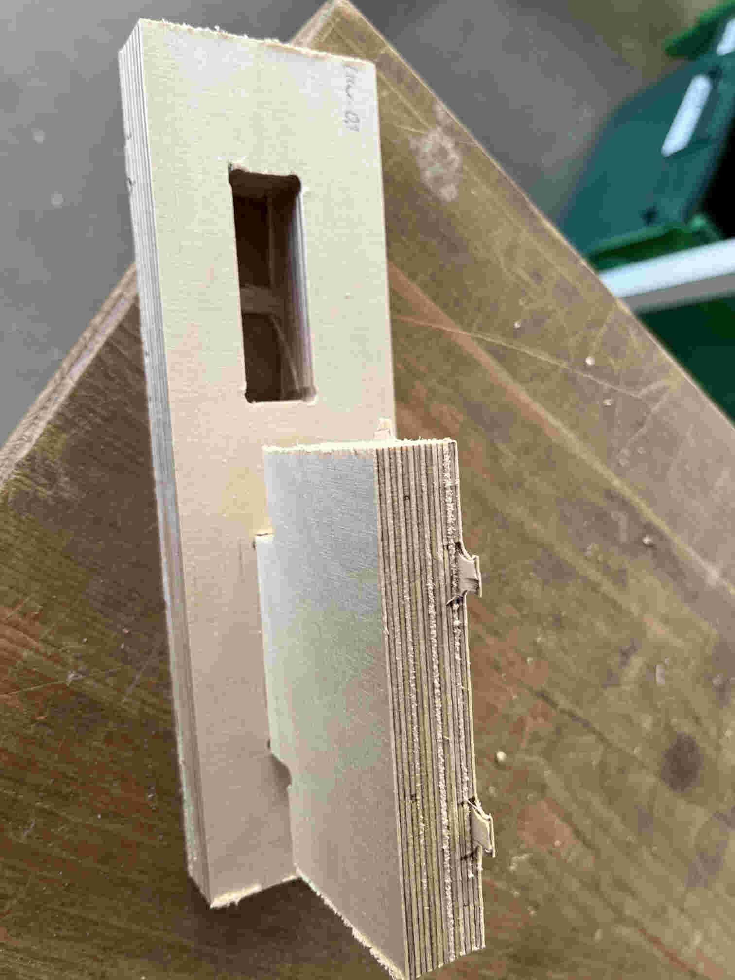
So I went ahead and added the 0.2 mm clearance to all my joints.
Preparing the Rack CAM
After all design parts were ready, I needed to nest them such that they'd fit on the 1400x800 mm2 bed.
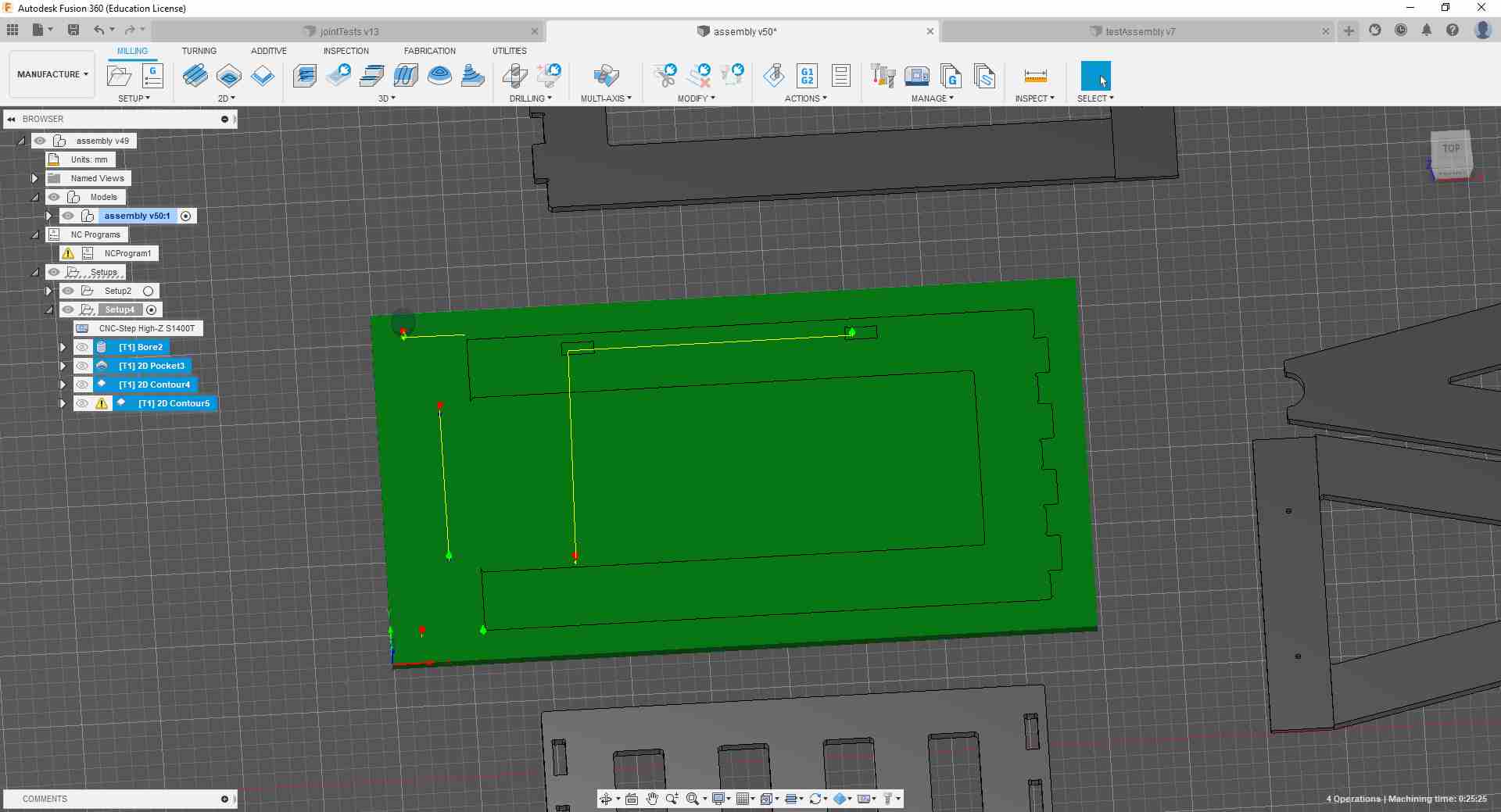
And then I started creating the CAMs for all of them.
.jpg)
And then off to Post Process.
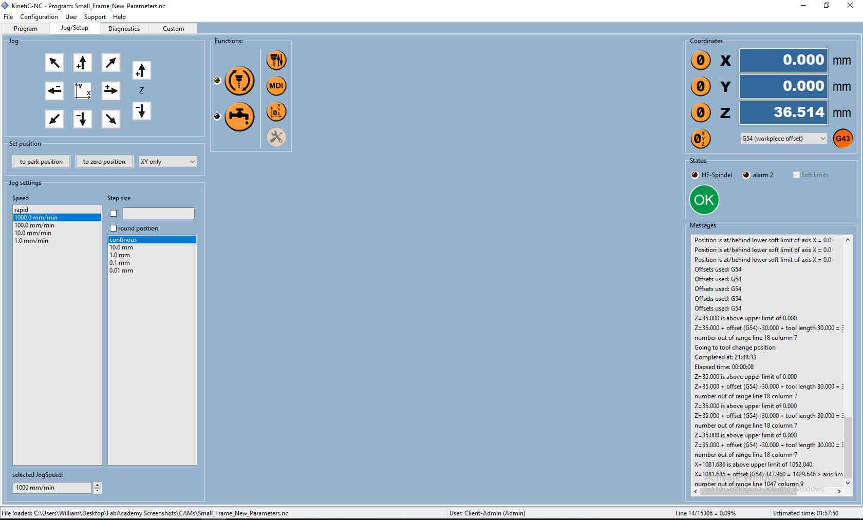
Off to KinetiC-NC and the CNC.
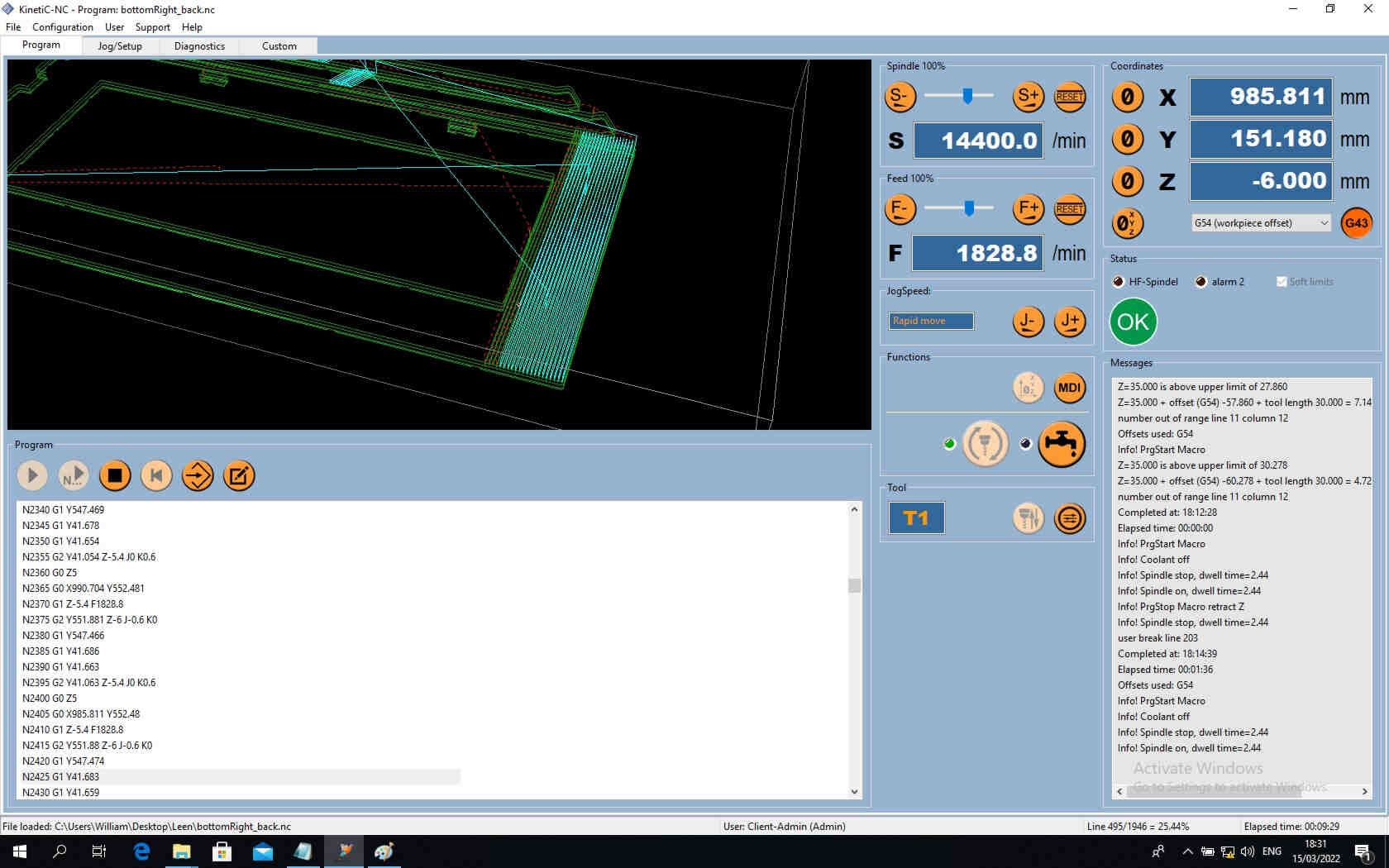
And again...we get the idea.
.jpg)
.jpeg)
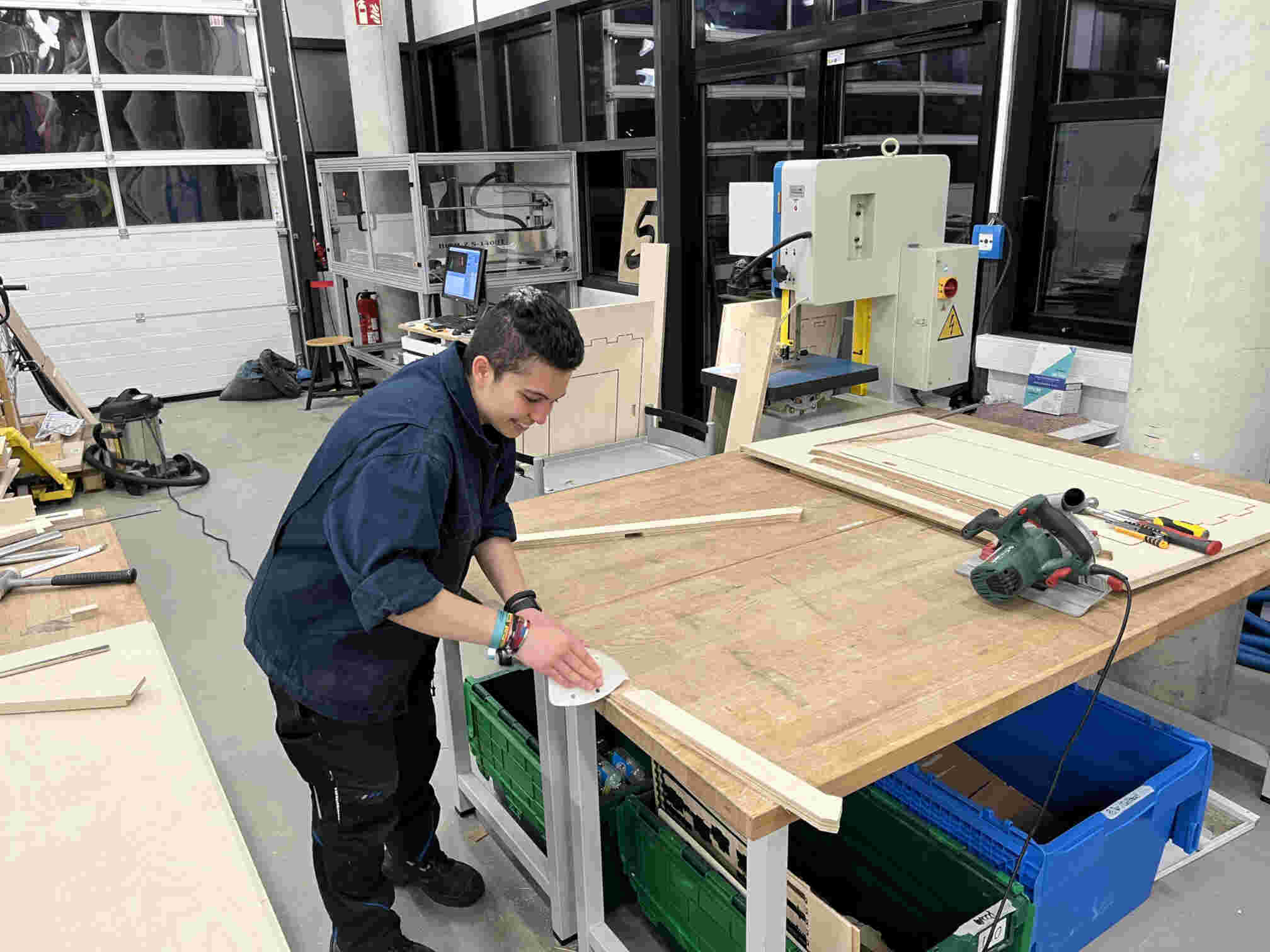
Getting there, with a little bit of a nudge.
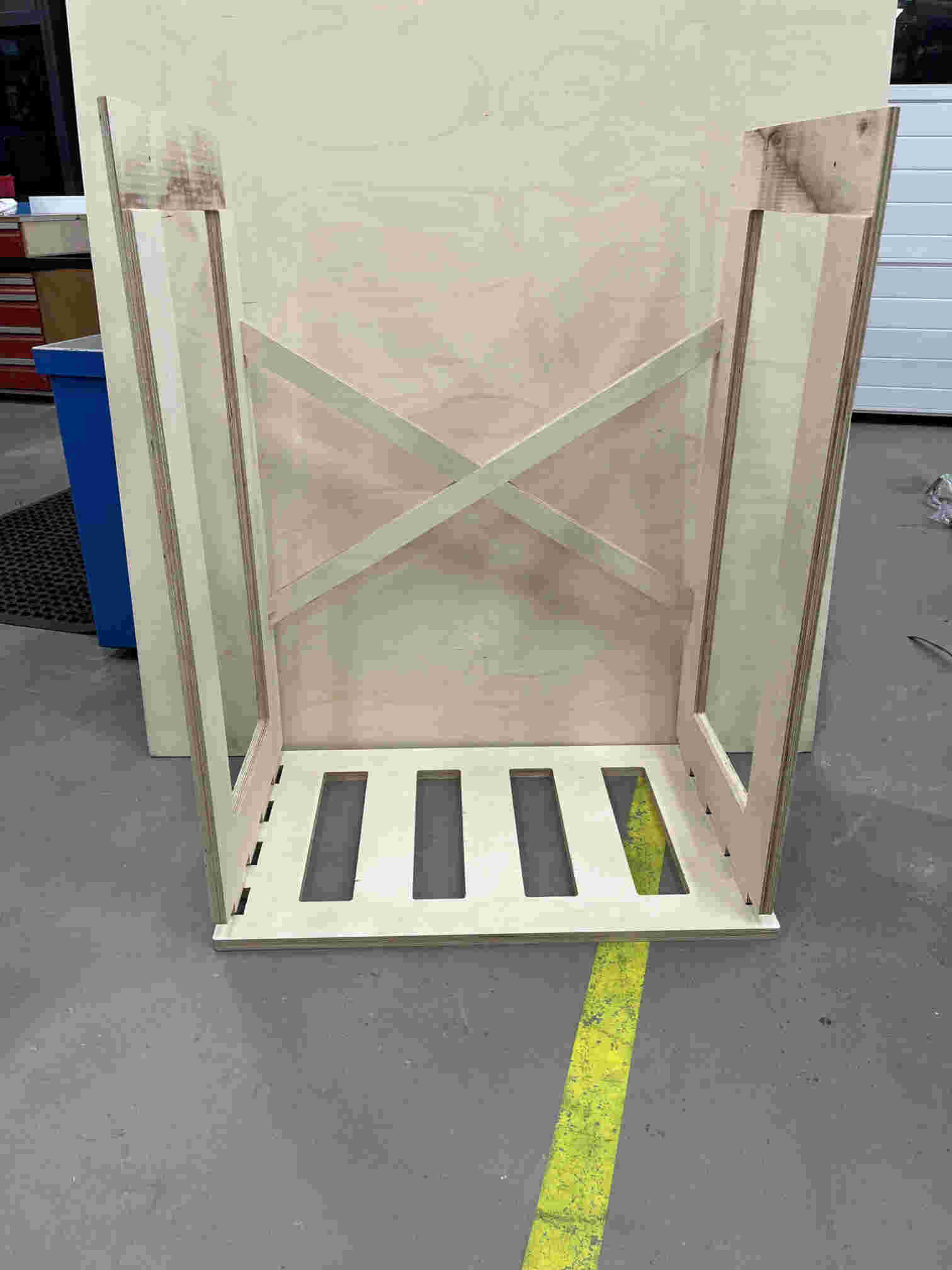
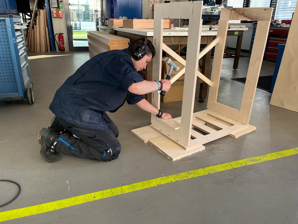
TADAA!