14. Networking and communications
GROUP ASSIGNMENT
- Send a message between two projects
Desde el siguiente link se puede acceder al Group Assignment: Group Assignment
INDIVIDUAL ASSIGNMENT: Internet Protocol Slip / Serial RS232
- Design, build, and connect wired or wireless node(s) with network or bus addresses
I tried to work with the SLIP protocol but couldn’t get it to work, therefore I opted to use the RS232 serial asynchronous communication protocol. More information about how this protocol works in the following link: rs232-serial-communication
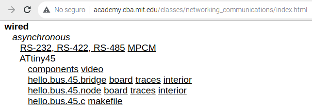
Therefore, I decided to make the cards to test the RS232 protocol that can be found at the following link: networking_communications/index
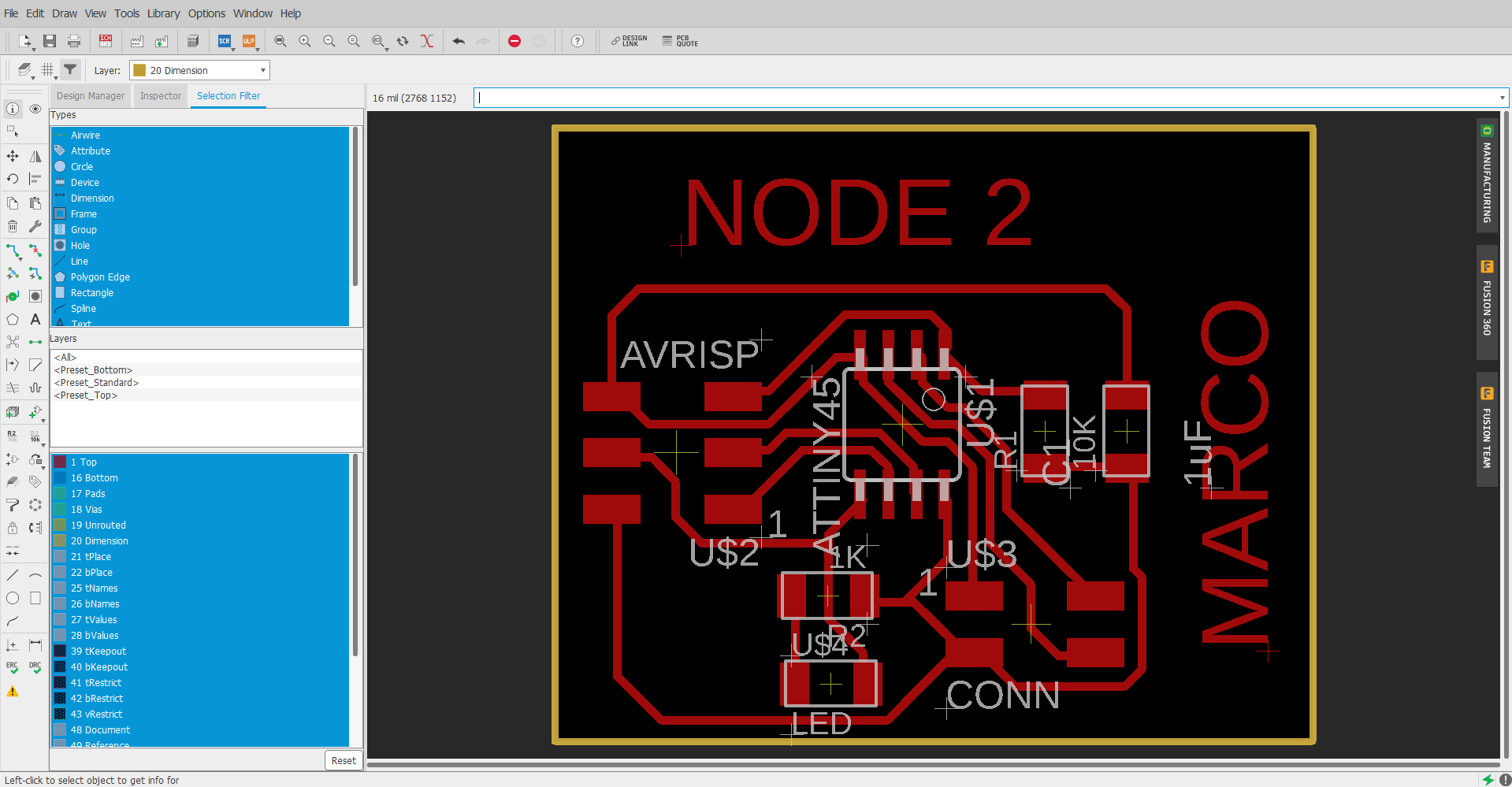
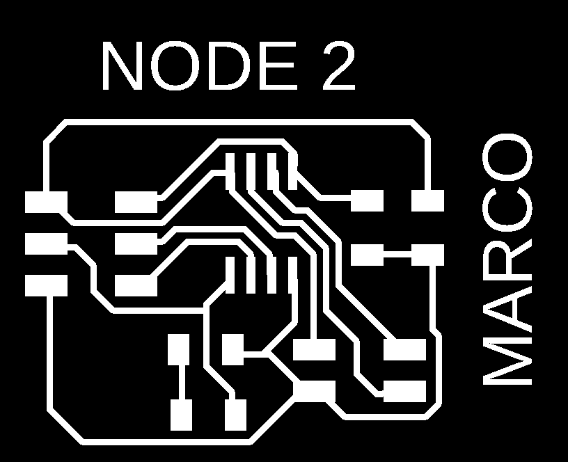
Following the example I made my own plates using Eagle. (02) plates for the knots and (01) for the bridge.
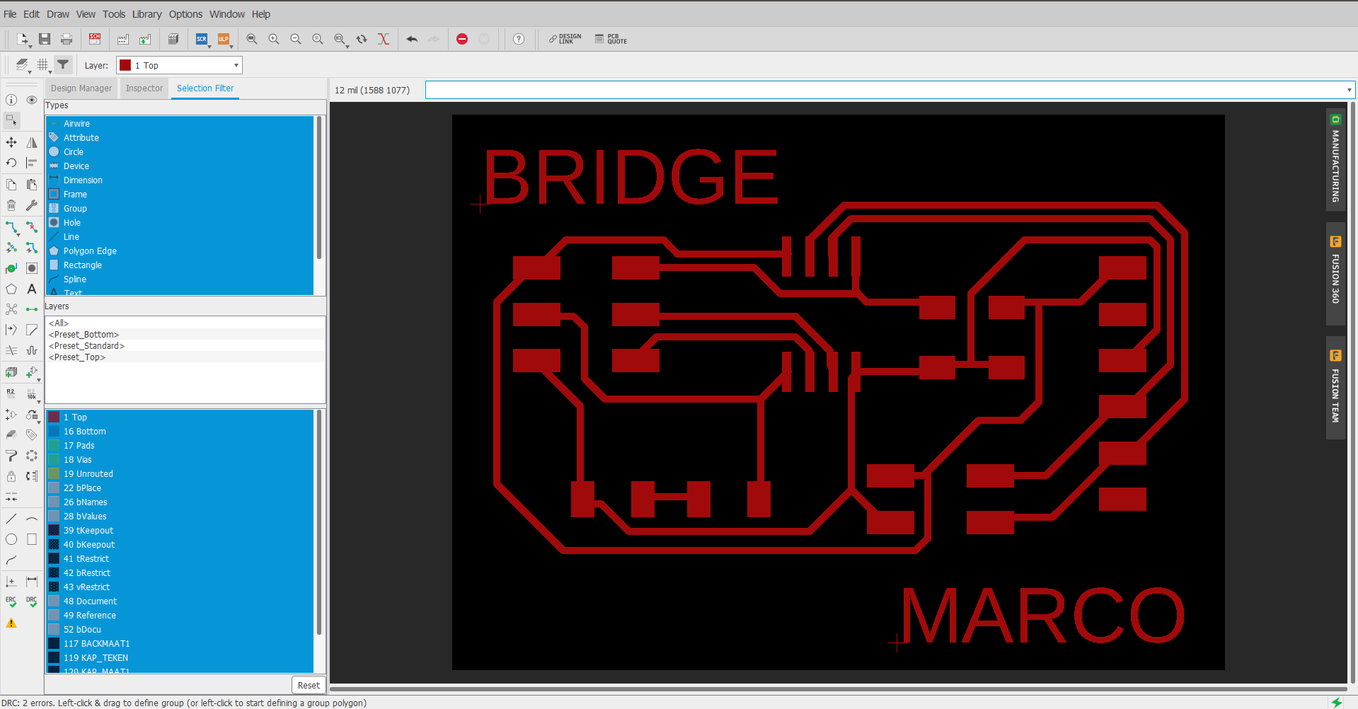
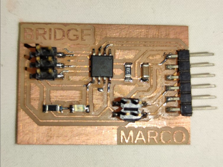
BRIDGE
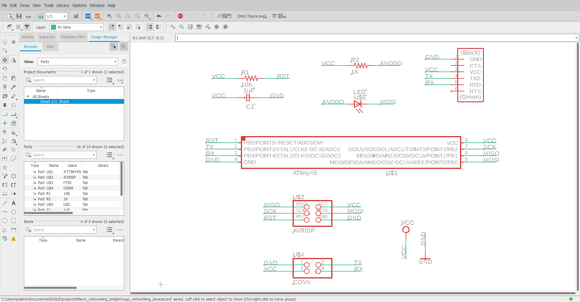
The component list: (01) Attiny45 (01) Capacitor 1uF (04) 10K Resistor (01) LEDs (01) 1K Resistor (01) FTDI 6x1 Connector (01) 3x2 ISP Connector
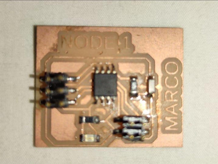
NODE
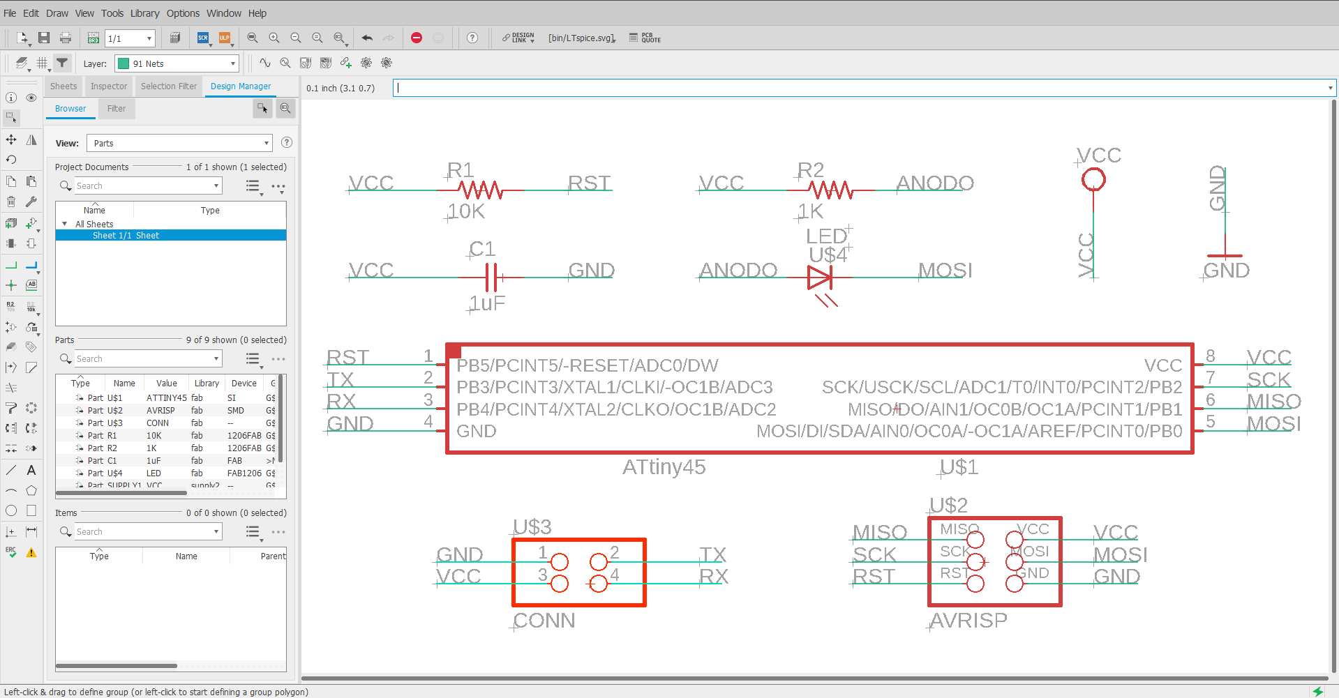
The component list:
-
(01) Attiny45
-
(01) Capacitor 1uF
-
(04) 10K resistor
-
(01) LEDs
-
(01) 1K resistor
-
(01) 2x2 Connector
-
(01) 3x2 ISP connector
I make 2 Node type plates and to differentiate them each plate indicates Node 1 and Node 2

After manufacturing the plates and soldering the components look like this:

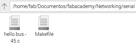
Proceed to download the files:
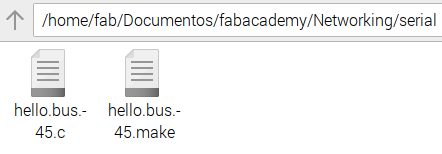
Then we need to rename the hello.bus.45.make file to Makefile
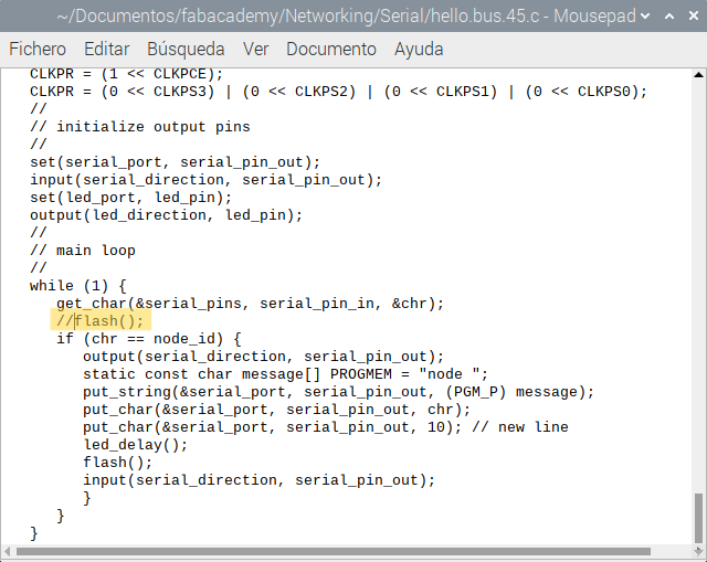
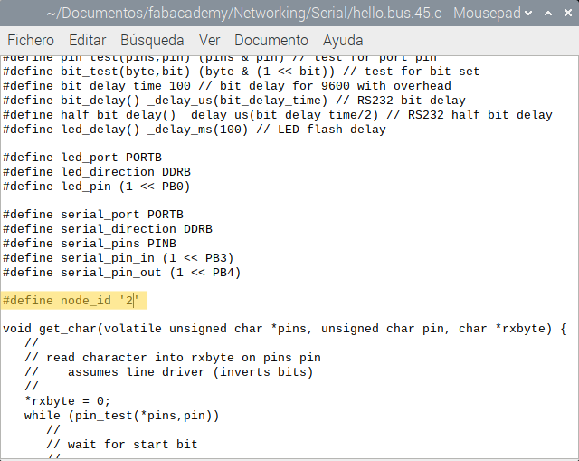
Before programming you have to edit the file hello.bus.45.c
Proceed to commenting out the line with the flash() function that comes before the if() structure. With this modification, the leds of each card will light up only when they correspond, that is, if I send a message to node 1, only the led of node 1 should light up.
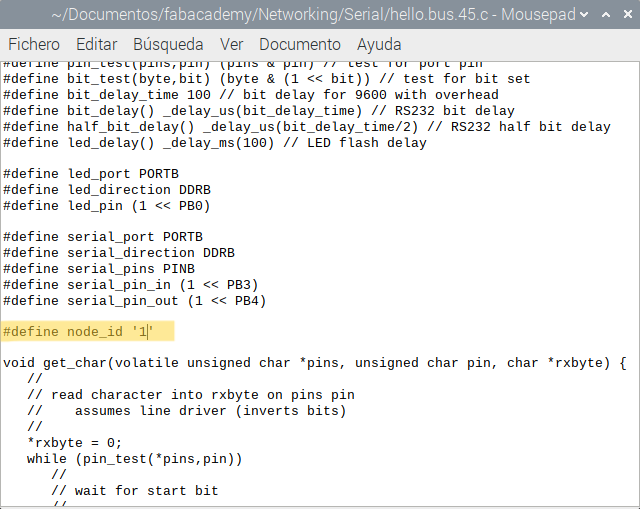
We must also modify the identifier (ID) for each card as appropriate:
Bridge → node_id ‘0’ node 1 → node_id ‘1’ node 2 → node_id ‘2’
By default, it is with the value 0 corresponding to the bridge. Therefore, when we want to program the nodes, we will have to modify the ID accordingly.
Connect the USBTiny programmer and FTDI cable to the Bridge board

Then we check the connections from the terminal with the lsusb command
Finally, from the linux terminal we access the folder with the .c and Makefile files and execute the following command:
make program-usbtiny

We repeat the process for the nodes, previously editing the file as previously defined.
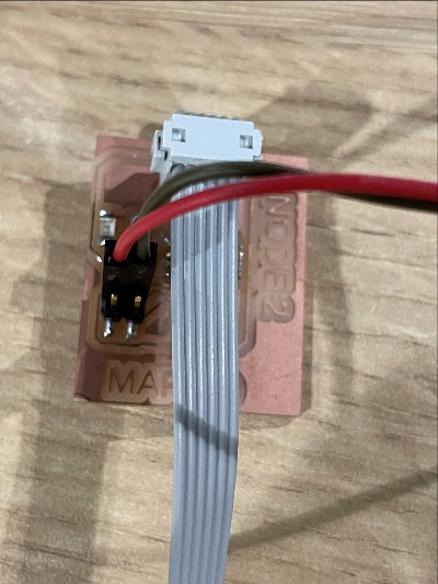
After programming the boards we make the connection between them as shown in the image, consider that in each connector the communication lines (RX, TX) and power supply (VCC, GND) must coincide point to point.
To carry out the tests we need to execute the file term.py From the linux terminal we execute the following command: python term.py /dev/ttyUSB0 9600
A window opens and we press the numeric keys: 0 → To send a message to the Bridge and turn on its LED 1 → To send a message to Node 1 and turn on its LED 2 → To send a message to Node 2 and turn on its LED
PCD Design and Programming files: