11. Input devices
GROUP ASSIGNMENT
For this assignment, 2 sensors were tested: an inclination sensor and a light sensor.
Tilt sensor A tilt sensor is a digital sensor that detects the tilt, vibration, or sudden movement of an object. More information at the following link: https://learn.adafruit.com/tilt-sensor
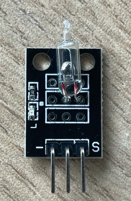
We use an Arduino board to make the connections and do the tests with the oscilloscope.
We build the following circuit:

and we program the Arduino with the following code:
/ Better Debouncer * * This debouncing circuit is more rugged, and will work with tilt switches! * * http://www.ladyada.net/learn/sensor/tilt.html /
int inPin = 2; // the number of the input pin int outPin = 13; // the number of the output pin
int LEDstate = HIGH; // the current state of the output pin int reading; // the current reading from the input pin int previous = LOW; // the previous reading from the input pin
// the following variables are long because the time, measured in milliseconds, // will quickly become a bigger number than can be stored in an int. long time = 0; // the last time the output pin was toggled long debounce = 50; // the debounce time, increase if the output flickers
void setup() { pinMode(inPin, INPUT); digitalWrite(inPin, HIGH); // turn on the built in pull-up resistor pinMode(outPin, OUTPUT); }
void loop() { int switchstate;
reading = digitalRead(inPin);
// If the switch changed, due to bounce or pressing… if (reading != previous) { // reset the debouncing timer time = millis(); }
if ((millis() - time) > debounce) { // whatever the switch is at, its been there for a long time // so lets settle on it! switchstate = reading;
 // Now invert the output on the pin13 LED
if (switchstate == HIGH)
  LED state = LOW;
else
  LED state = HIGH;
} digitalWrite(outPin, LEDstate);
// Save the last reading so we keep a running tally previous = reading; }
We connect the oscilloscope to digital input 02 and GND to monitor the behavior.
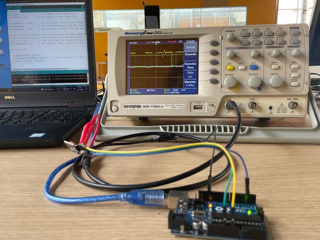
We verify the behavior of the digital signal, we can appreciate the 5V amplitude pulses.

Light Sensor (LDR) A light sensor is an analog sensor whose resistance varies linearly as light intensity varies. More information at the following link: https://learn.adafruit.com/photocells

We use an Arduino board to make the connections and do the tests with the oscilloscope.
We build the following circuit:

and we program the Arduino with the following code:
/* Photocell simple testing sketch.
int photocellPin = 0; // the cell and 10K pulldown are connected to a0
void setup(void) { // We’ll send debugging information via the Serial monitor Serial.begin(9600); }
void loop(void) { photocellReading = analogRead(photocellPin);
Serial.print(“Analog reading = “);
delay(100); }
We connect the oscilloscope to the analog input 0 and GND to monitor the behavior of the photocell.
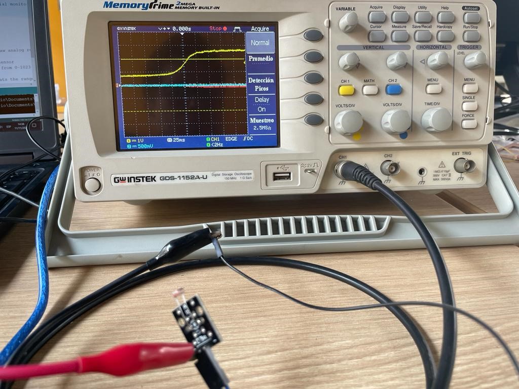
We verify the behavior of the analog signal, we can appreciate the variation of the wave along the maximum amplitude of 5V.
INDIVIDUAL ASSIGNMENT: Magnetic sensor
- Measure something: add a sensor to a microcontroller board that you have designed and read it
For this week I decided to work with Hall effect magnetic sensors. More information on how these sensors work at the following link: electromagnetism
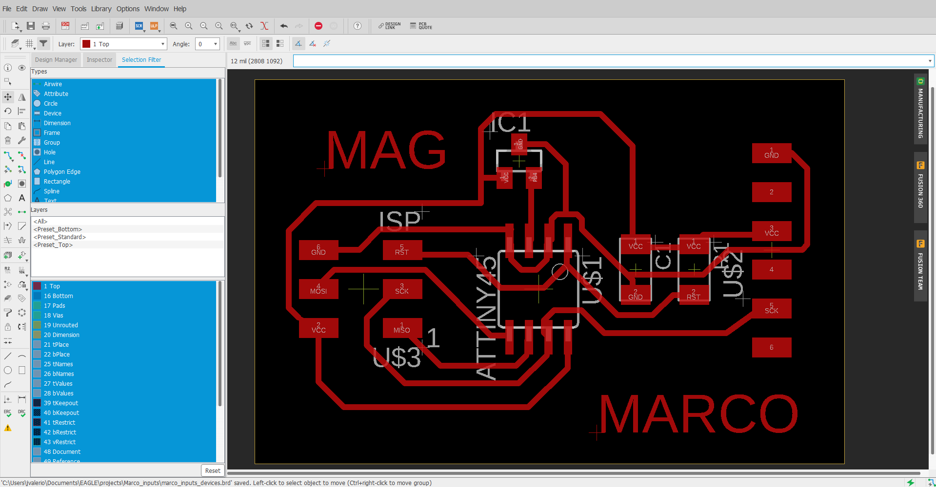
Therefore, I decided to make the card for Hall effect sensors that can be found in the following link: input_devices

Guided by the example, I make my own board using Eagle:

The list of components:
-
(01) Attiny45
-
(01) 1uf Capacitor
-
(01 10K resistor
-
(01) Hall effect sensor A1324
-
(01) Connector FTDI 6x1
-
(01) ISP Connector 3x2
You can download the Hall effect sensor data sheet from the following link: Datasheet
After soldering the components, the board looked like this:

I proceed to download the files:
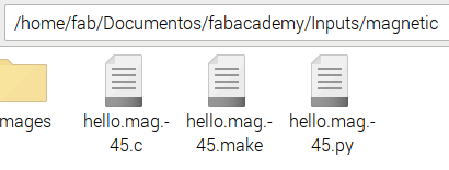
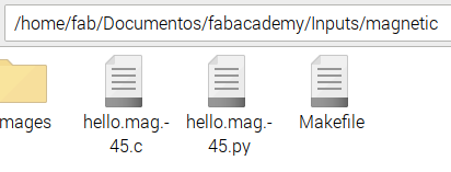
Then we have to rename the hello.mag.45.make file to Makefile
Connect the USBTiny programmer and FTDI cable to the board

Then we check the connections from the terminal

Finally, from the linux terminal we access the folder with the .c and Makefile files and execute the following command:
make program-usbtiny

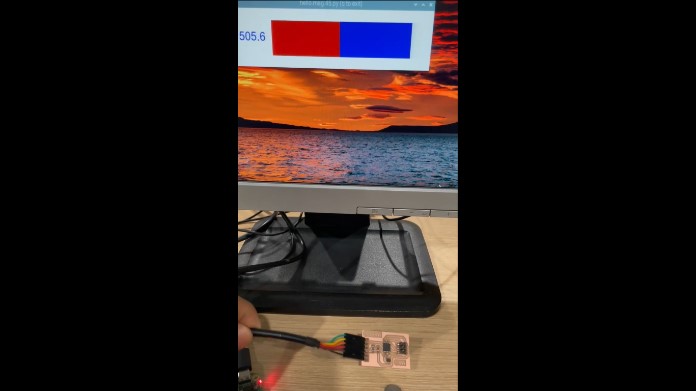
To perform the tests we need to execute the file hello.mag.45.py
First we edit and comment the following lines

From the linux terminal: python hello.mag.45.py /dev/ttyUSB0 9600
and we test the sensor with a magnet.
Watch video:
The files: