12. Output devices
GROUP ASSIGNMENT
- Measure the power consumption of an output device
From the following link you can access the Group Assignment: Group Assignment
SINGLE ASSIGNMENT: RGB LEDs
- Add an output device to a microcontroller board you’ve designed, and program it to do something
For this week’s assignment I chose to work with the RGB LED. More information on how they work in the following link. electronics-basics-how-do-rgb-leds-work
I took as reference the card for RGB LEDs that is in this link: output_devices

Guided by the example I made my own plate using Eagle.
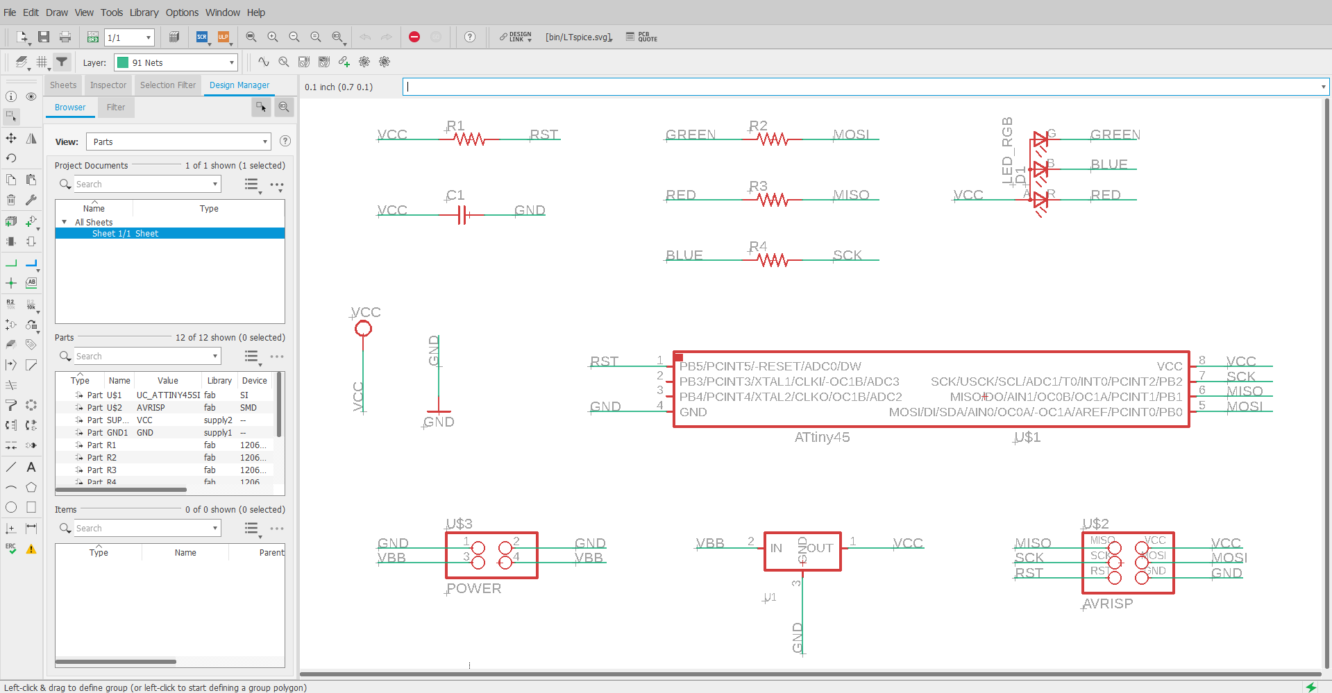

The list of components:
-
01) Attiny45
-
(01) 1uf Capacitor
-
(01) 10K resistor
-
(01) RGB LEDs
-
(02) 1K resistor
-
(01) Resistor 499
-
(01) Regulator 5V
-
(01) Connector 2x2
-
(01) ISP Connector 3x2
You can download the RGB LED data sheet from the following link: HB-CLV1A-FKB
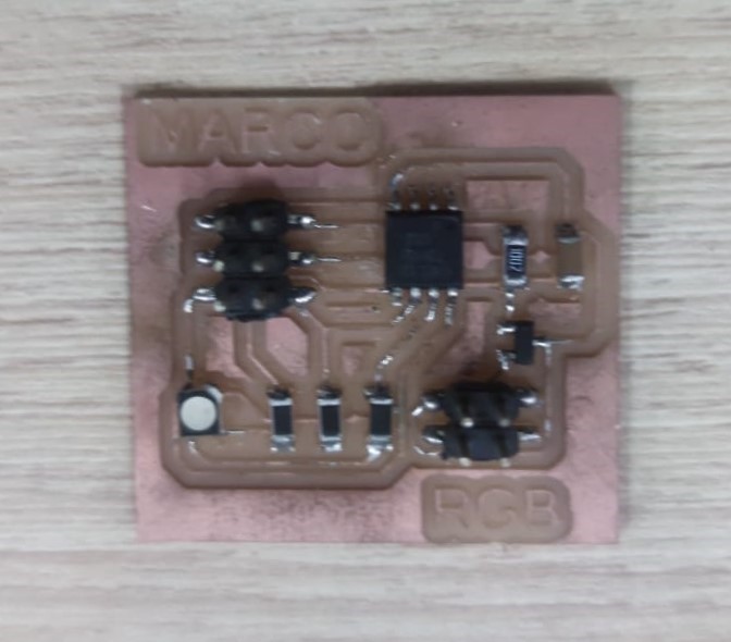
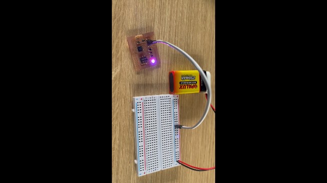
After soldering the components, the board looked like this:
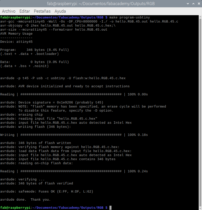
To program the board I downloaded the .c and .make files


Finally, from the linux terminal we access the folder with the .c and Makefile files and execute the following command:
make program-usbtiny
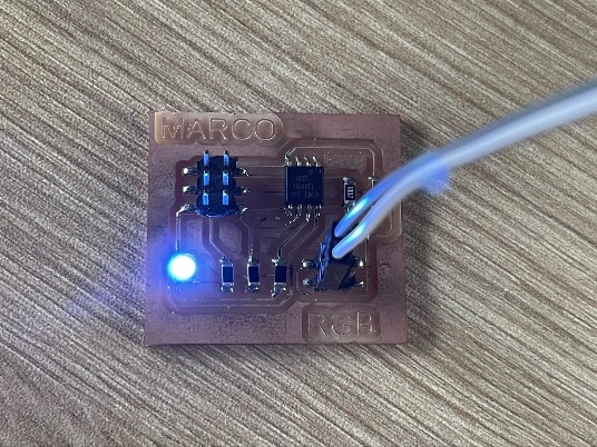
When we finish programming, we carry out the tests:
Watch video:
The files: