5. Electronics production
Group Assignment
- Characterize the design rules for your in-house PCB production process: document feeds, speeds, plunge rate, depth of cut (traces and outline) and tooling.
From the following link you can access the Group Assignment: Group Assignment
Individual Assignment
-
Make an in-circuit programmer that includes a microcontroller
-
Optionally customize it
-
Mill and stuff the board
-
Test it to verify that it works
-
Extra credit: try other PCB processes
This week we have to make the recorder for our electronic cards. It is the first of many printed plates that we are going to manufacture.
First we must download the files from the recorder or programmer, each programmer is designed to program a specific type or family of microcontrollers. In my case I am going to work with ATMEL Attiny 44 and 45 microcontrollers.
Then we download the files from the following link:


I am going to work with the MODELA MDX-20 milling machine and the FabModules software.
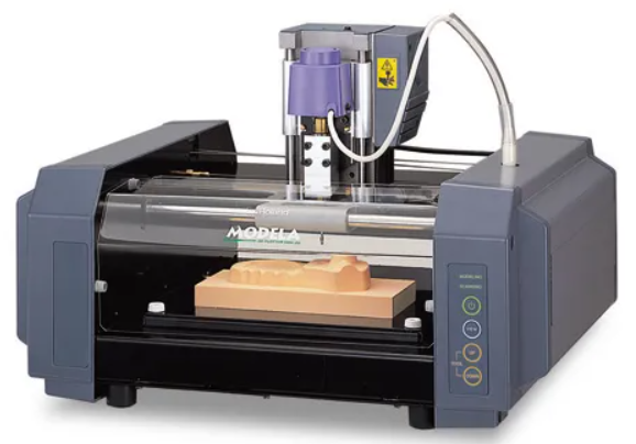
Specifications: Maximum Working Area: 203.2mm (X) x 152.4mm (Y) x 60.5mm (Z) Maximum Table Load Weight: 1kg (2.2lbs) Compatible Materials: ABS,acrylic, wood, plaster, styrene foam, chemical wood, wax, plaster, polyacetal, ploycarbonate, Sandomur SS, aluminum, brass Weight of Unit: 13.7kg (30.2lbs)

The milling process consists of 2 parts:
-
Routes
-
External cut
The file corresponding to the circuit routes is: hello.ISP.44.traces.png

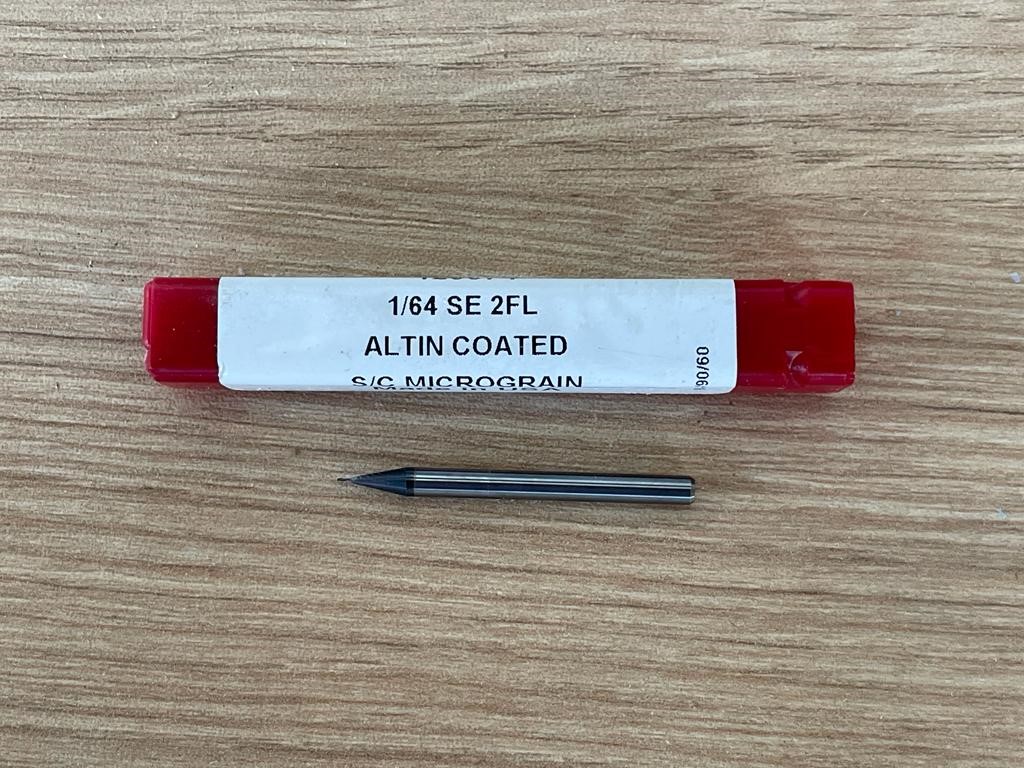
To make this card we must use the 1/64 milling cutter
We follow the following procedure to mill our printed plate:
- With the equipment turned off, we place the milling cutter in the actuator and adjust it well.
- We turn on the MODEL MDX-20 with the STANDBY button.
- Then we press the VIEW button so that the actuator moves to the coordinate origin position.
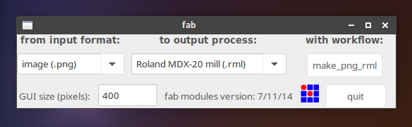
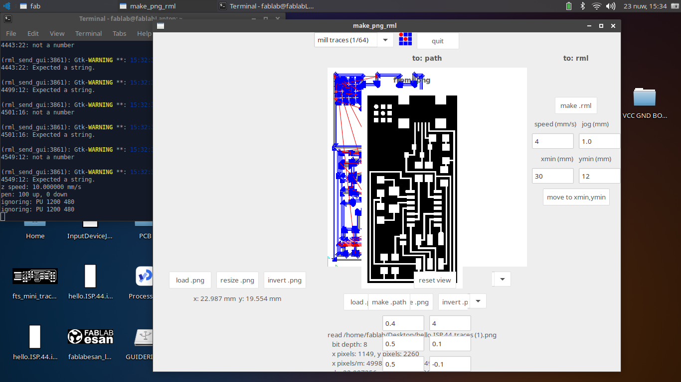
- We load the FabModules from the computer and select: a. Input format: image (.png) b. Output process: Roland MDX-20 mill (.rml) c. Workflow: make_png_rml
- From the FabModules we can move the actuator to the desired position to start the milling process. In the Xmin and Ymin boxes we enter the coordinates and press the Move to xmin, ymin button
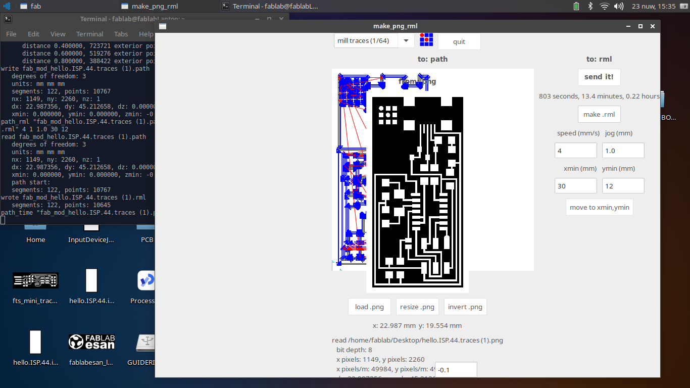
- We choose the process to mill the routes: mill traces 1/64
- We load the file by pressing the load .png button
- And then we modify the Error parameter with the value 0.1
- We press the button make .png
- Then the button make .rml
- Finally, the button send it! and the Modela Output window will open
- Z axis calibration is done manually, by pressing the DOWN button until the cutter makes contact with the bakelite plate.
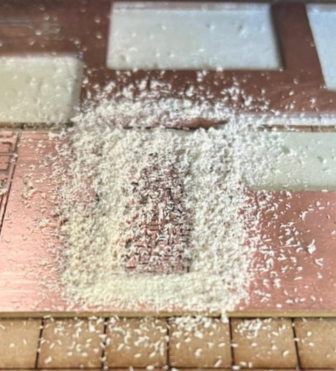
- We start the milling process by pressing the Begin button in the Modela Output window.

We verify the manufacturing process
We repeat the process for the external cut of the PCB.
This time we use the file hello.ISP.44.interior.png

For this we must change the strawberry for the 1/32

We repeat the procedure until step 6 and this time we choose the process mill inside 1/32 and continue with the rest of the steps in the same way.
Once the plate is finished, we clean it and then proceed to solder it.

With all the components at hand I can now proceed to solder my board.
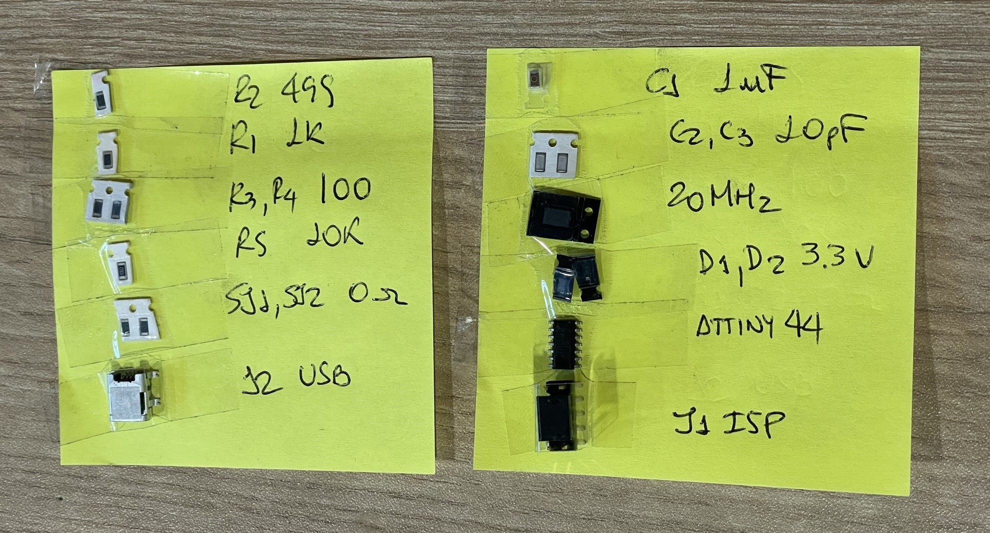
The recommendation is to start soldering the smallest components first and so on according to size.
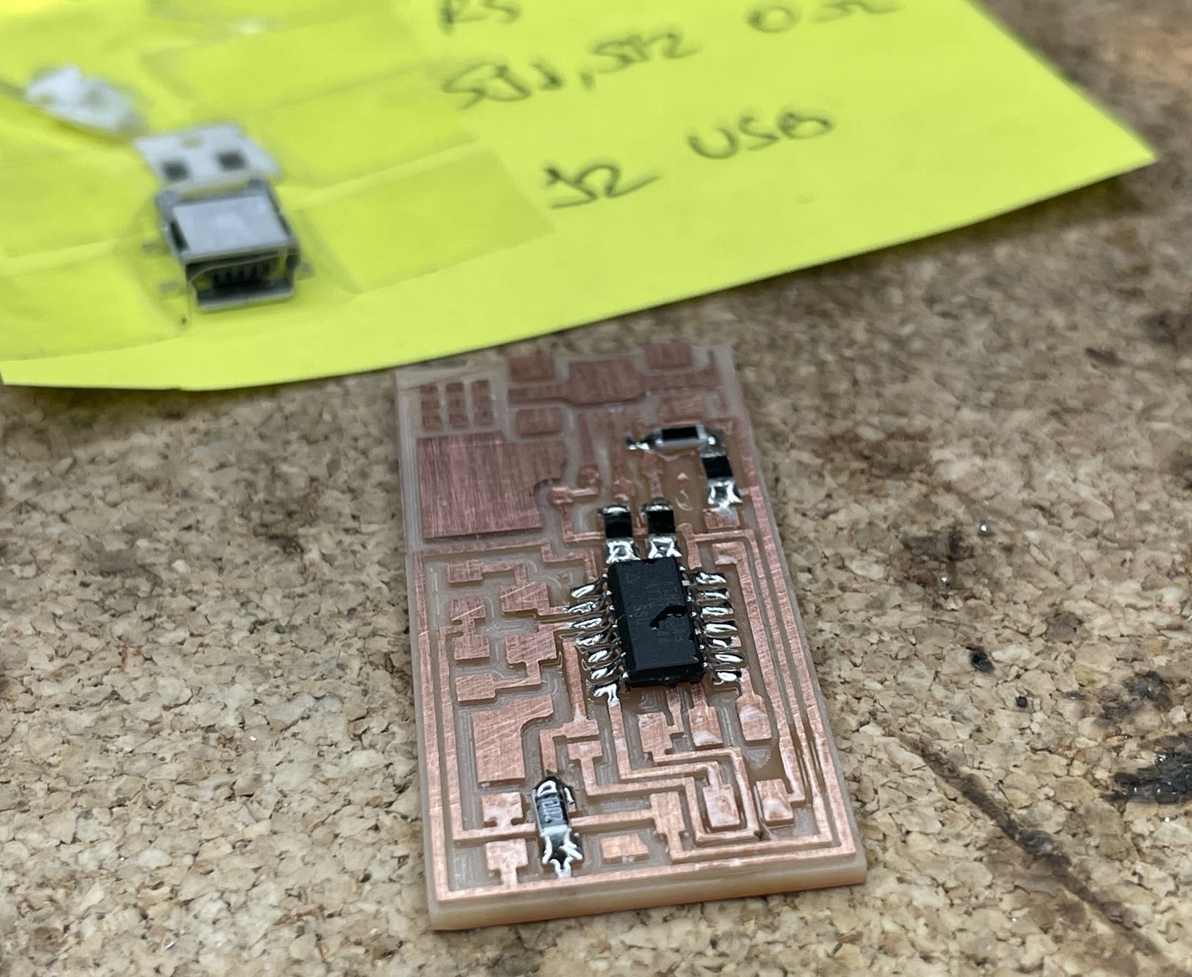
With the board finished, I now proceed to program it.

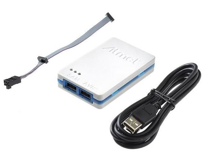
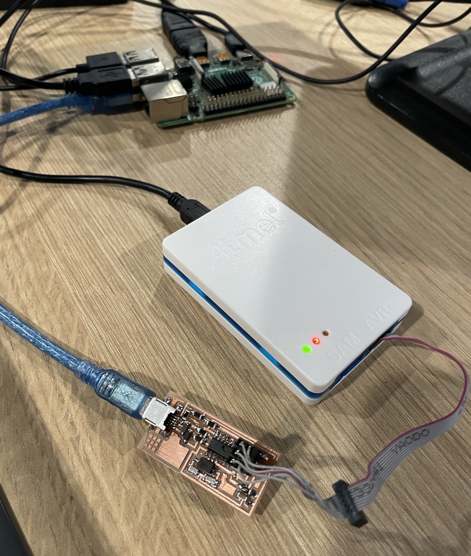
To program this panel it is required to have another programmer. In my case I used Microchip’s ATMEL ICE which is compatible with both AVR and SAMD microcontrollers.
The connection would be like this:
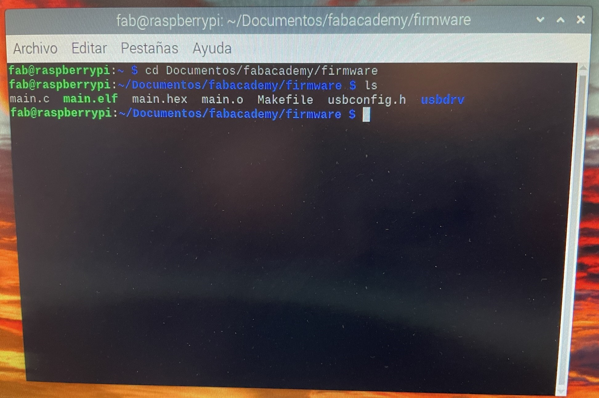
Of the files that we downloaded at the beginning, there is a .zip file that contains all the firmware files to program the board. We unzip them and access these files from the Linux Terminal.
I modify the Makefile file, since we must indicate which recorder we are going to use to carry out the programming. We replace the text avrisp2 with atmelice_isp

Having made the change, we execute the following commands, as indicated in the tutorial that we can find at this link: FabISP
- To remove files older than the build: makeclean
- To compile and rebuild the files needed for programming: make hex
- To configure the internal registers of the microcontroller (Attiny44): make fuses
- To program the card: make program
At the end of the programming, we remove the jumpers JP1 and JP2 from the PCB; We connect the board to the computer and check if everything is OK and the Operating System recognizes the driver as Multiple Vendors USBtiny
