7. Electronics design
This week we worked on electronics design.
Group Assignment
- Use the test equipment in your lab to observe the operation of a microcontroller circuit board
From the following link you can access the Group Assignment: Group Assignment
Individual Assignment
In the first text field we add the path of the folder that we unzip

We check the folders

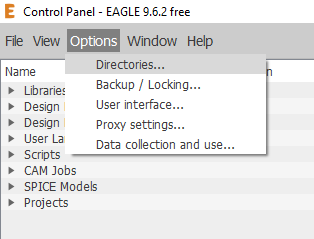
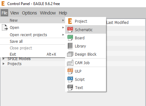
Making Plate We enter Eagle, select the option File> New> Schematic
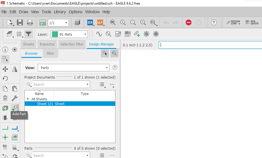
After selecting the “Schematic” option, a new project window will not appear, in it we must choose the “Add part” option that appears in the toolbar on the left side of the window.
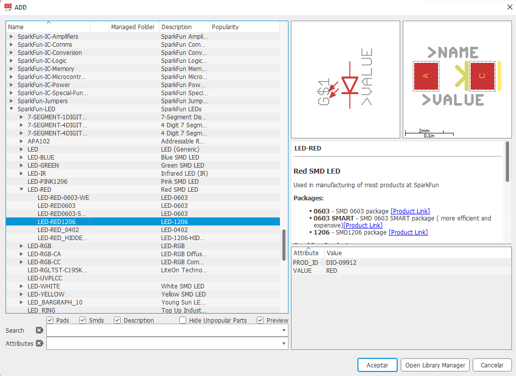
The window will appear with all the components, arranged in alphabetical order, available to add in Eagle
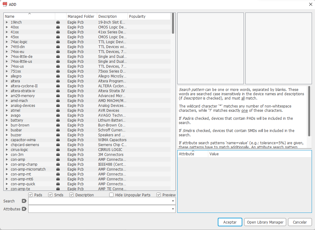
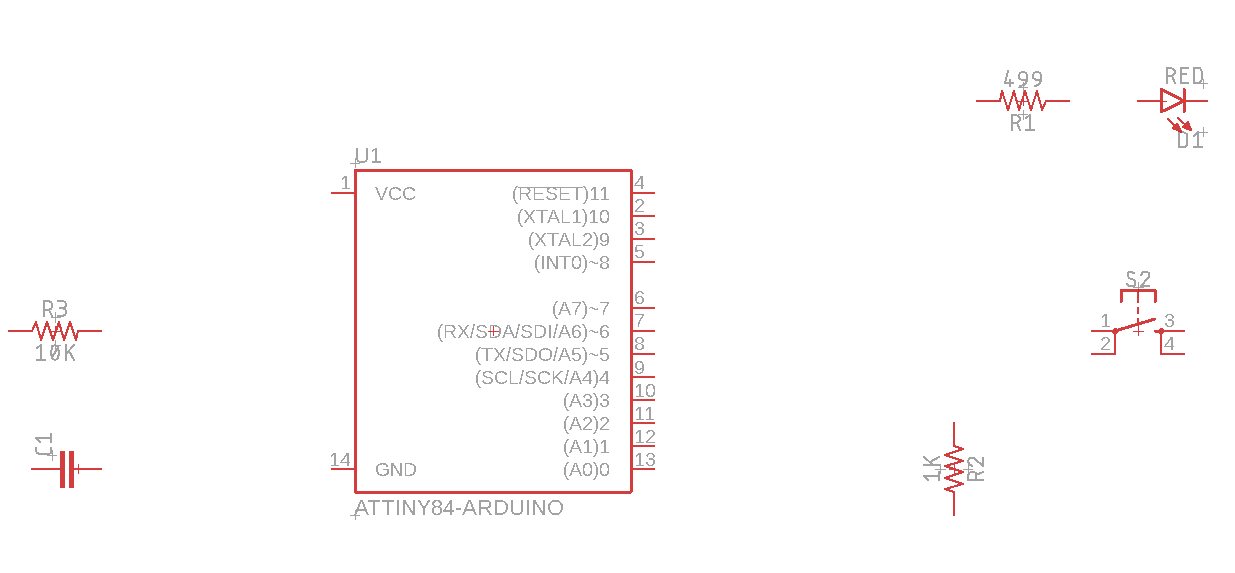
We will use the ATtiny44 microcontroller and we can find it inside the “Sparkfun-IC-Microcontroller” library, with the name “ATTINY84-ARDUINO”, we select it and press “OK”.

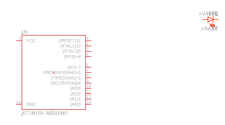
We locate the place where we want to place the component and we click to embed it in the worksheet.

Then we press the “ESC” key to return to the component window. In the same way we will add an LED in the “Sparkfun-LED” library, we select the color we want, in our case “LED-RED”, then we select “LED-RED1206” and add it in the schematic worksheet.
Note: we can rotate the components by right clicking on the schematic worksheet.
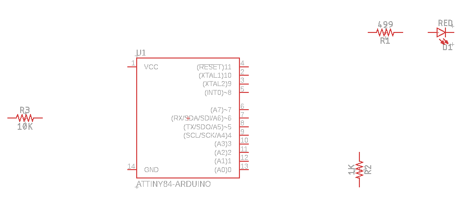
We add resistors from the “Sparkfun-Resistors” library, select the “RESISTOR” group within the library, then the “RESISTOR1206” component.

We add 3 resistors in the schematic worksheet.
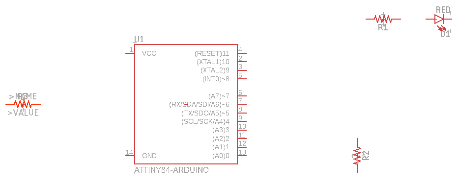
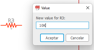
The resistors we add do not have an added value, so we must manually add each value. To do this we choose the “Value” option from the toolbar on the left side of Eagle.
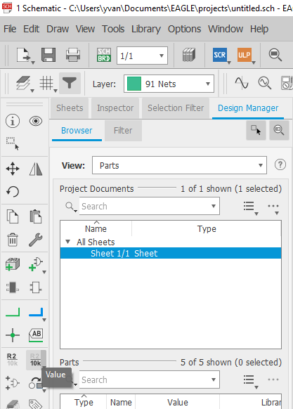
We click on each resistor in the schematic worksheet and it will ask us if we want to add a value.

After pressing “Yes”, we write the value that we want the resistance to have.
We do the same with the other two resistors. The worksheet will look like this:
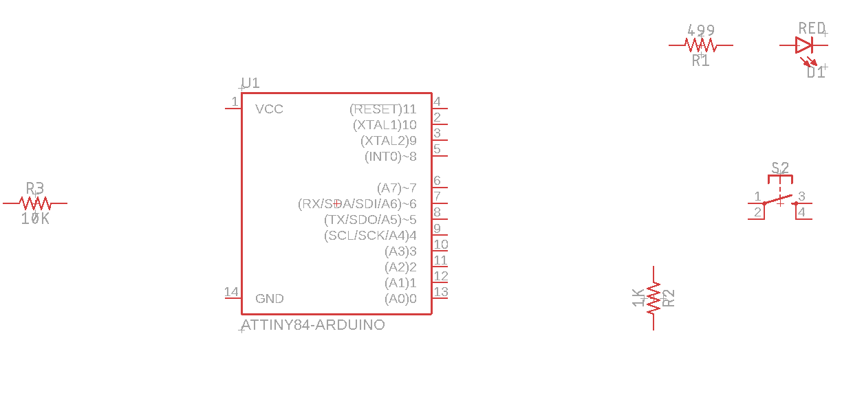
We add the switch from the “Sparkfun-switches” library, select the group “MOMENTARY-SWITCH-SPST-2”, then the component “MOMENTARY-SWITCH-SPST-SMD-2-4.6x2.8MM”

We add the component to the schematic worksheet
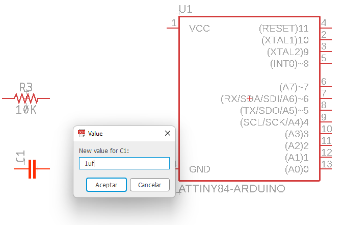
Then we add a capacitor, we place it in the “Sparkfun-Capacitors” library, in the “CAP” group, with the name “CAP-1206”.
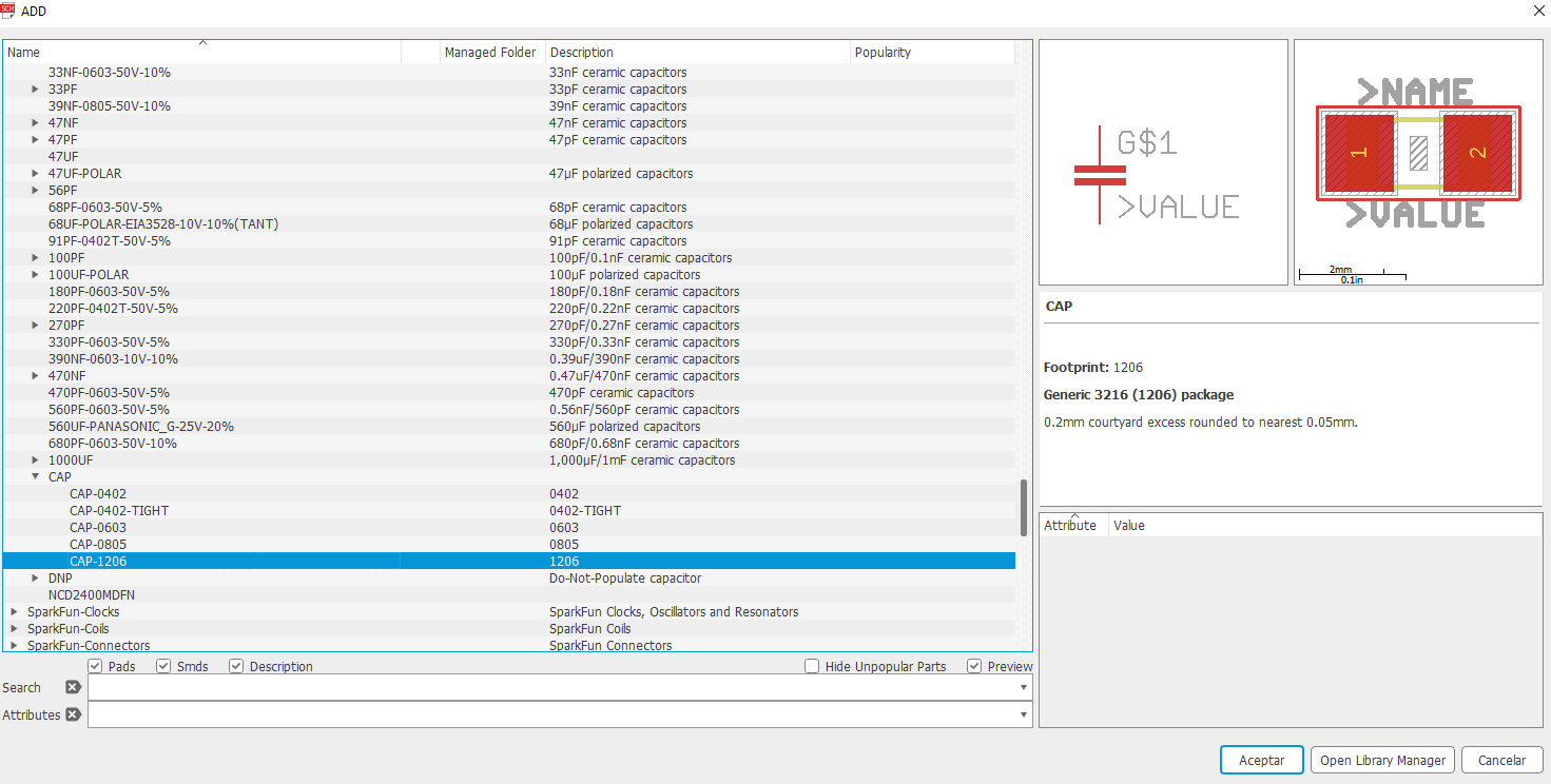
We add it to the schematic worksheet.
With the “Value” tool we add the value of 1uf to the capacitor.
We add 6X1 pins for the connections, from the “pinhead” library, inside the “PINHD-1X6” group.
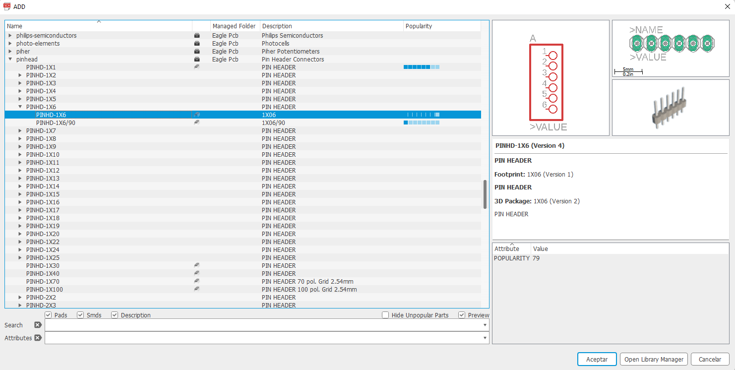
We placed it on the schematic worksheet.
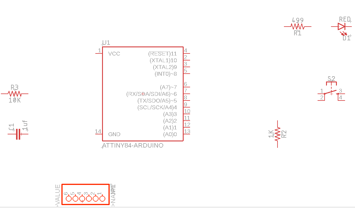
Similarly, we add a 6X2 sprat from the “”PINHD2X3” library.
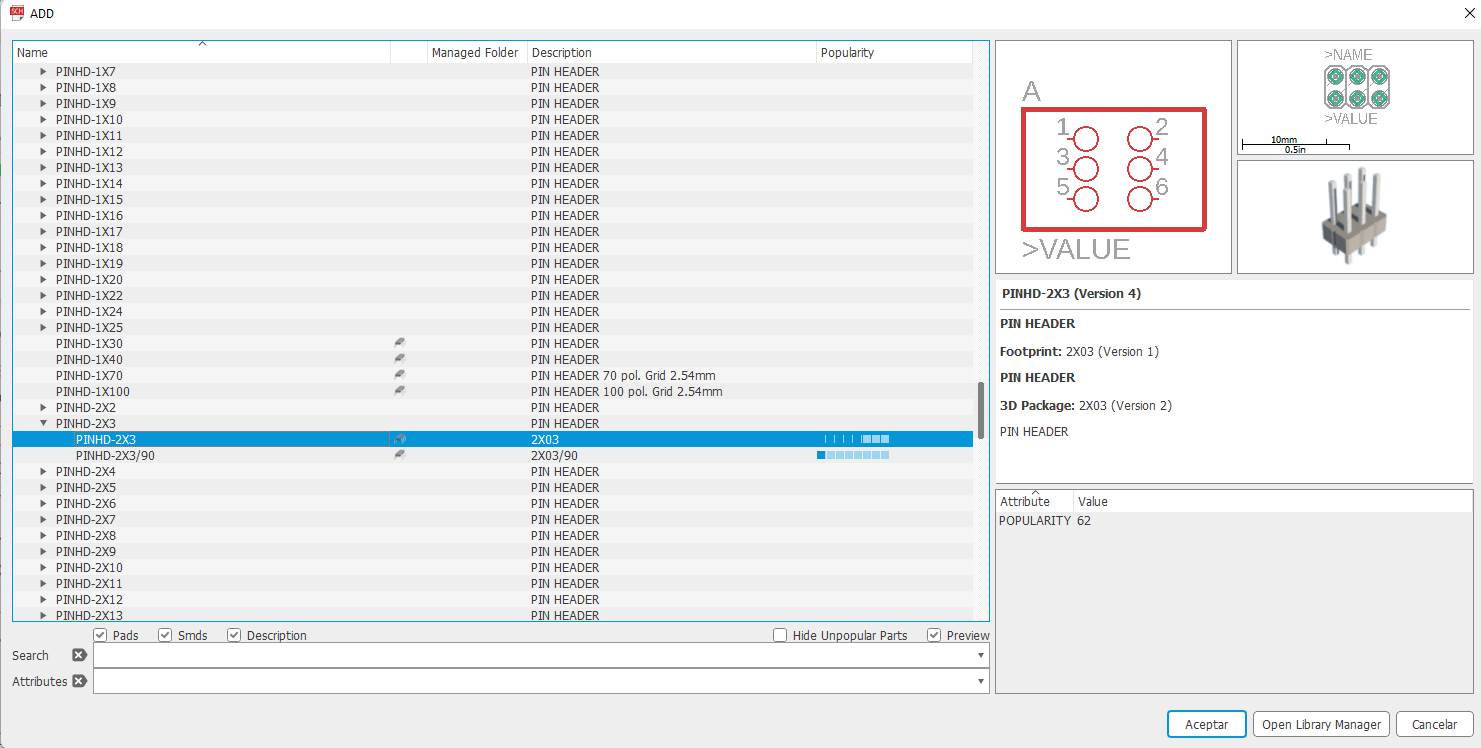
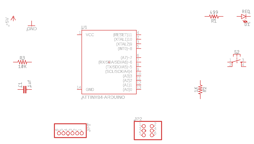
The workspace will look like this:

We add the 5 volt signal from “supply1”, with the name “+5V”.
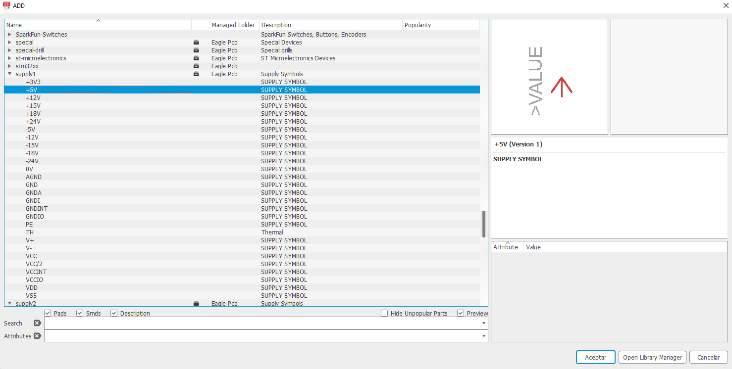
We also add the ground signal from “supply1”, with the name “GND”.

The schematic worksheet will look like this:
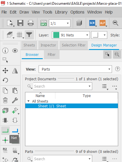
We add the connections between components with the “Net” tool
After adding the connections, the worksheet should look like this:

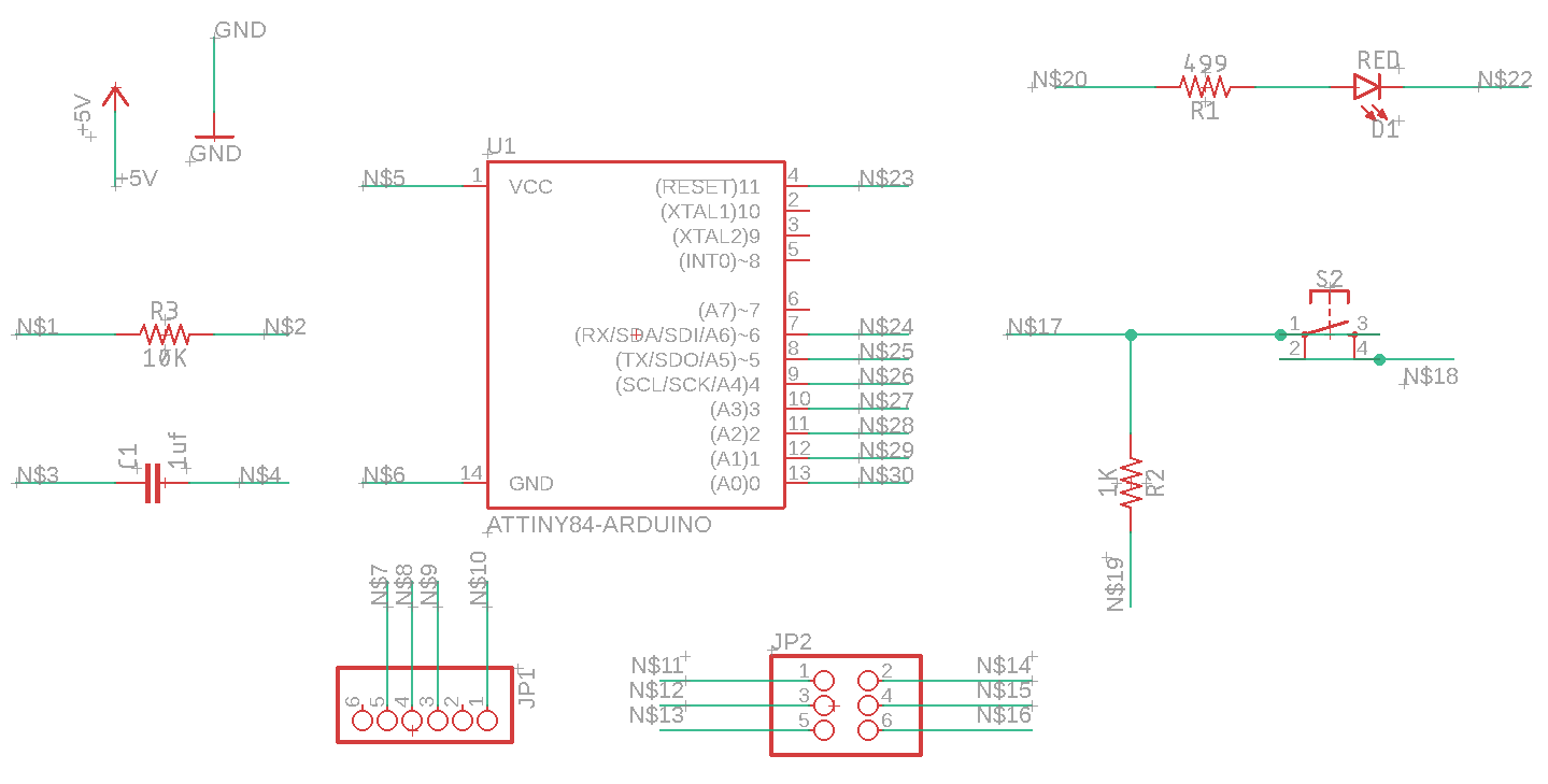
We add names to the signals with the “Label” tool
To add a name we just click on the green line that we need to name and Eagle will automatically create a name, we will have to choose the position of the name by moving the mouse and if necessary pressing the right button to rotate the name. After adding all the names the schematic worksheet will look like this:
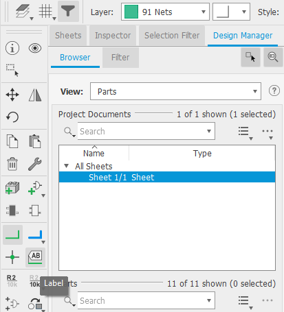
Finally we must change the names of the signals that we added with the “Name” tool.

After selecting the “Name” tool, we left click on each green line with a name and a window will appear to modify the name.
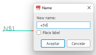
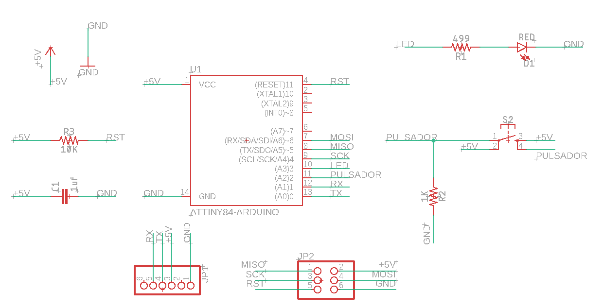
We must modify all the signals remaining as follows:
Designing the PCB board To create the PCB board from the schematic we will press the “Generate/switch to board” button to create the PCB board.
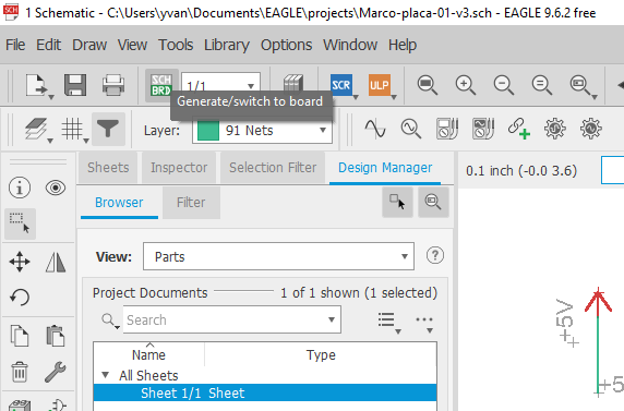
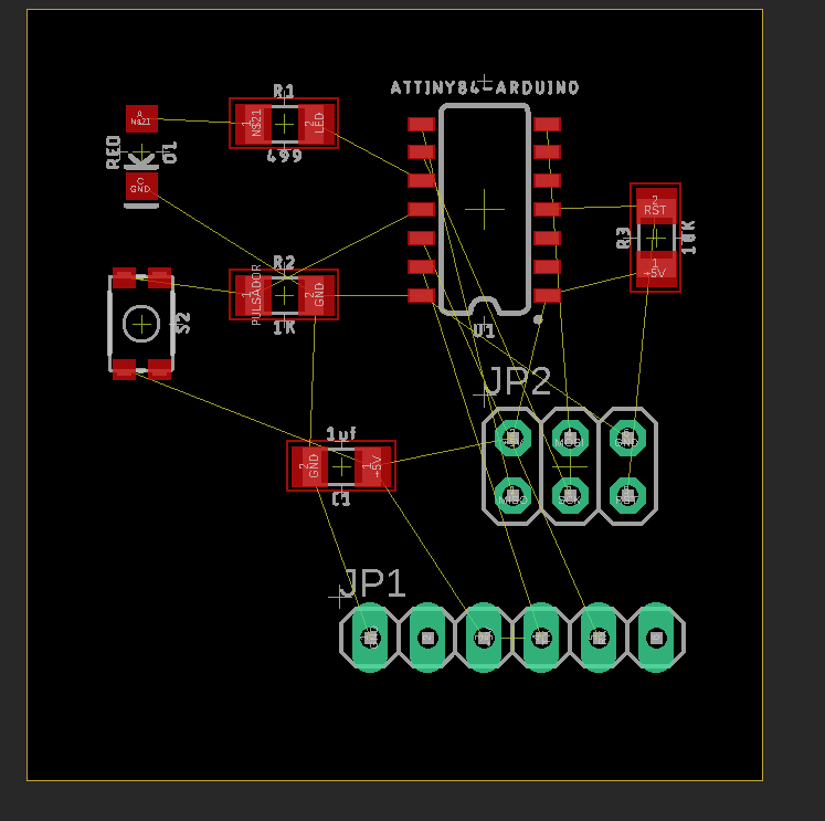
After creating the PCB board, the following window will not appear, where we can see all the components in real size:
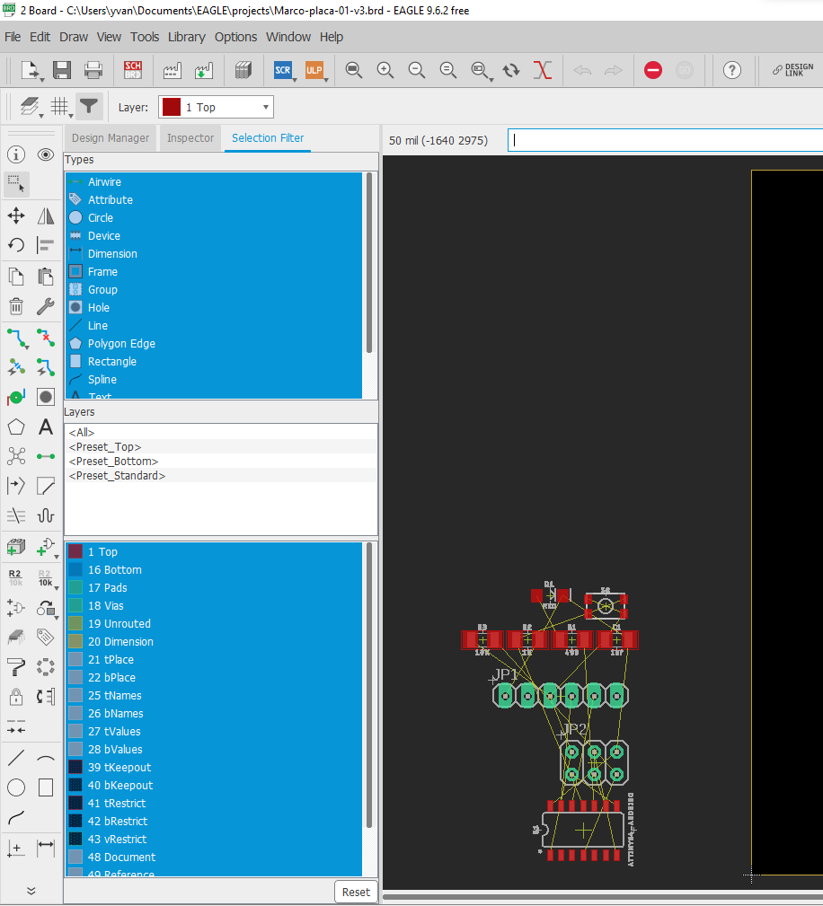
The black quadrilateral figure represents our PCB, we will have to add all the components on said plate. For this we will use the “Move” tool.
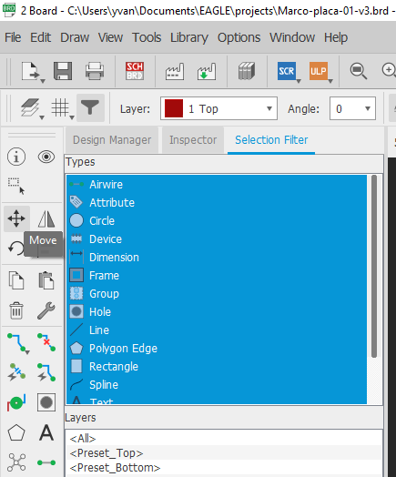
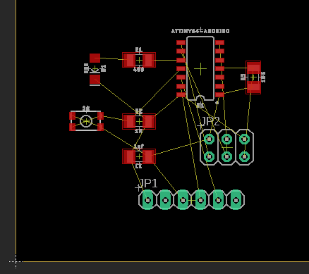
To use this tool, we click on the component we want to move and then drag it to its location. After moving all the components, the positions should not be as follows:
Then we must reduce the size of the PCB canvas with the same “Move” tool
To connect GND with the rest of the board we use the Polygon tool, to use it we select it in the toolbar on the left side.

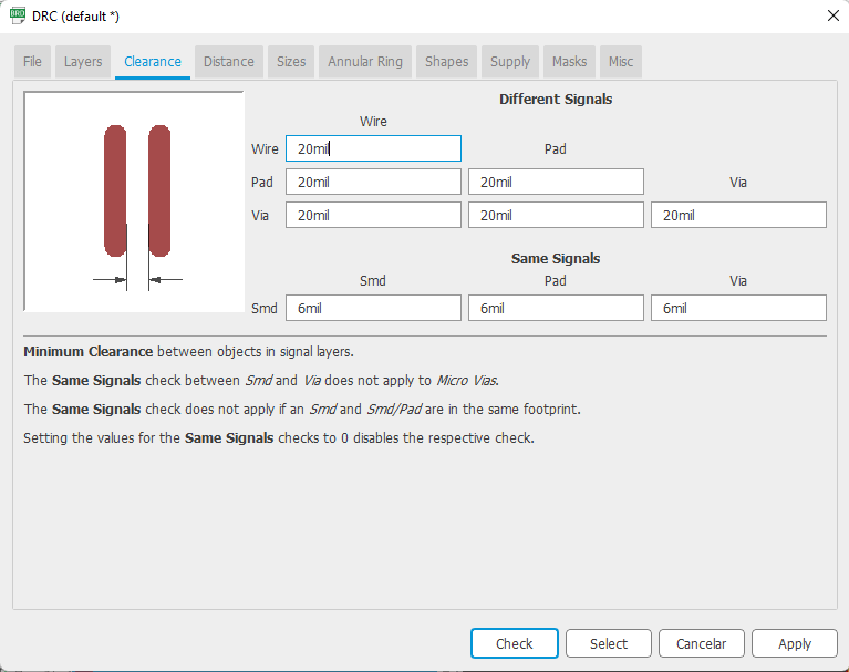
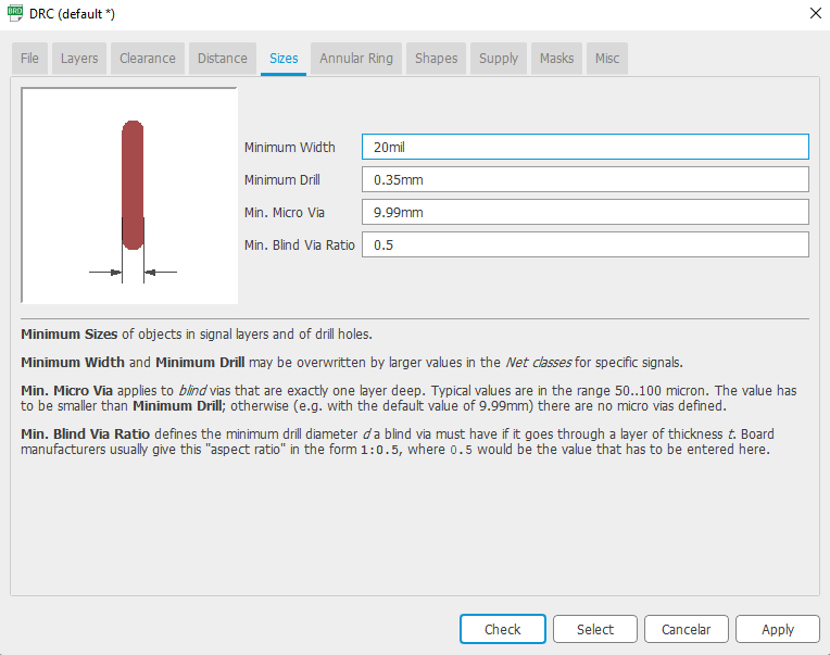
To draw the routes on the PCB we will use the “autorouter” tool, the “Tools” option to use it, we must first define the design rules. The definition of the design rules for autorouting can be found in Tools > DRC

In our case, we will modify the “Clearance” and “Sizes” rules with the following measures:
Then we select the option Tools > Autorouter
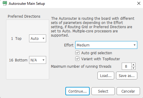
Then we press “Continue” and Eagle will start calculating the necessary tracks automatically. The result will be the following:
After selecting Polygon our cursor will allow us to draw a red line when we click on the work screen. We must draw a rectangle that covers the entire plate.

As we can see, additional tracks would be missing, which will be filled by means of bridges on the rear side of the board. To create bridges we select one of the missing connections to draw its bridge
we draw a route
With the “Vias” element of the toolbar we add the via to start the bridge.
We switch to the “Bottom” layer.
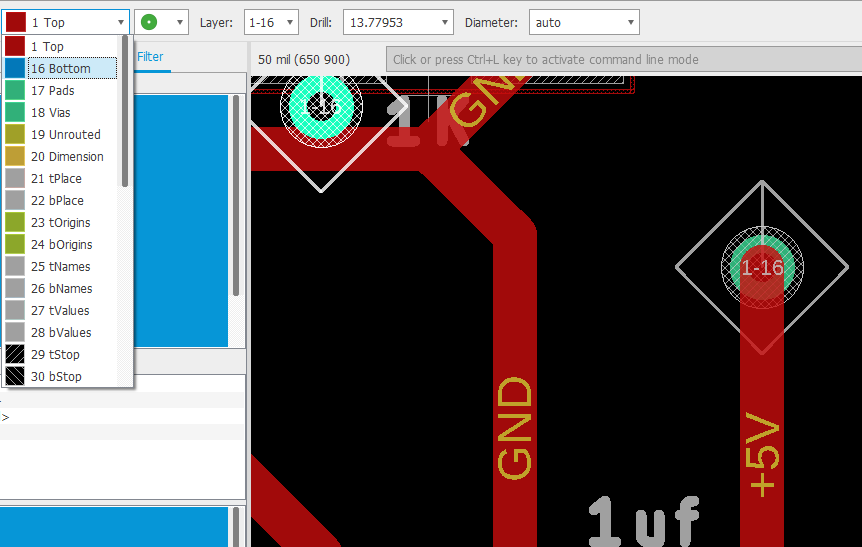
We select the route tracing tool again and trace the route of the bridge, it should come out in blue.

At the end of the bridge we add another way and our bridge will have been successfully created.

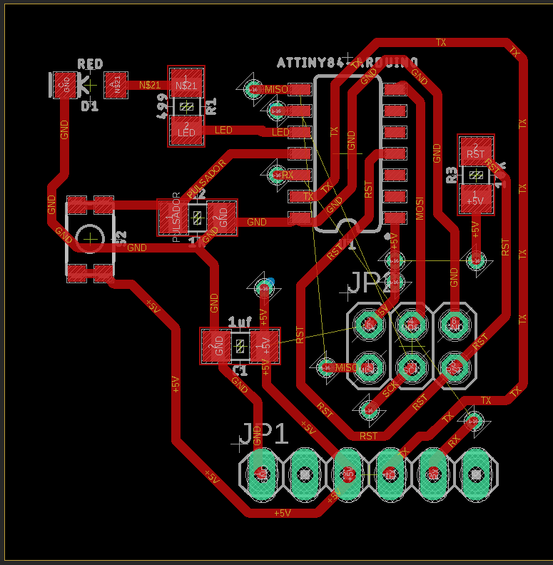
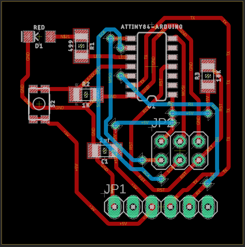
After tracing all the bridges, our plate should be left as follows:
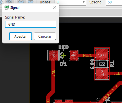
When we finish selecting the board, a dialog box will appear asking for the name of the signal to which we want to connect, we put the name GND.
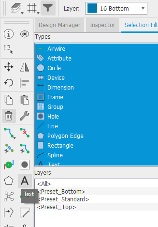
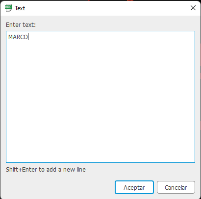
To customize we will use the “Text” tool.
In the pop-up window we add our name:
We press accept and make sure we have the Top layer selected and give it a size of 100.

We select the position and press click to add the text.
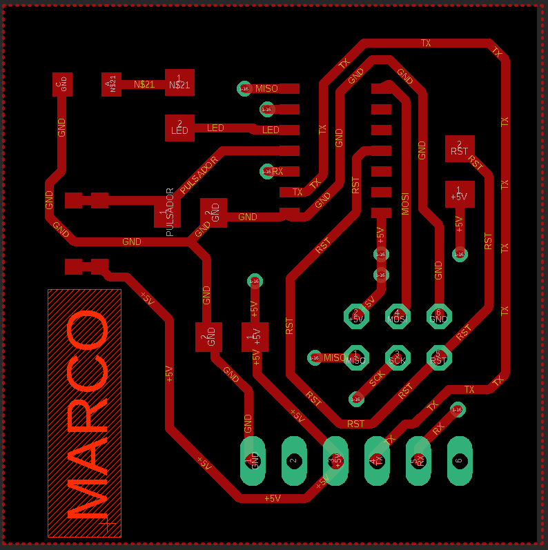
We press the “Rastnet” tool and generate our GND layer.
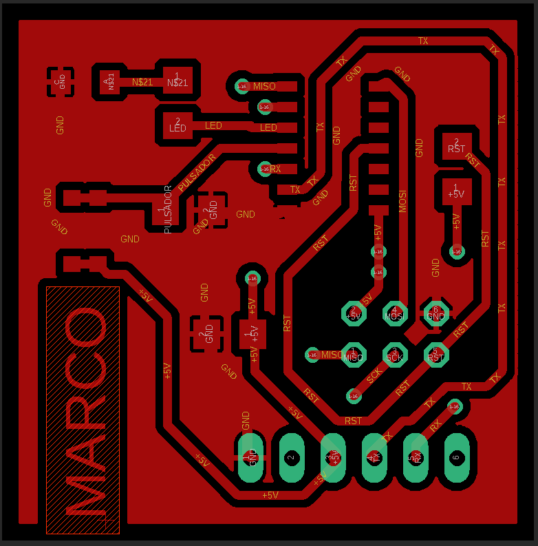
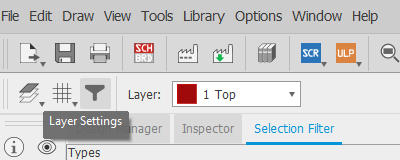
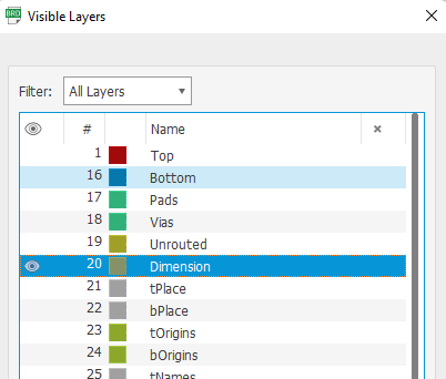
To print we must select the layers to print, for this we enter “Layer Settings”.
In our case we will leave the Top, Pads and Vias layers active.

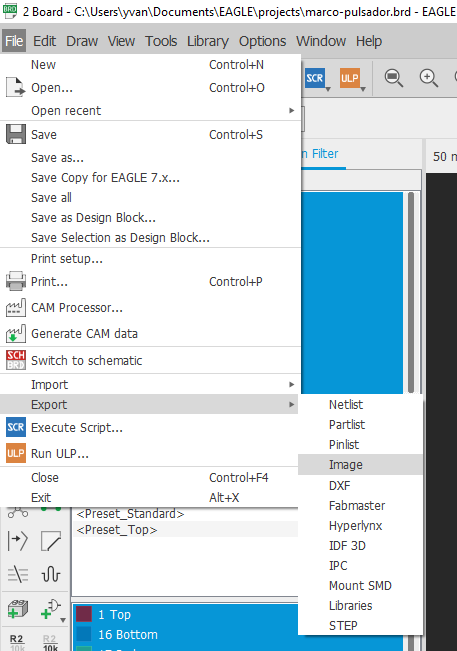
Then, we select the option Export > Image
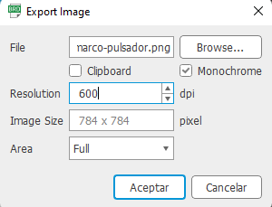
In the next window we write the following data, File we enter the name and the address where we want our image to be saved, then we press “OK”.
By reviewing the path of our file we will find the png generated with the following figure.

Additionally, we must add the dimensions, for this in “Layer Settings” we leave only the “Dimension” option marked.
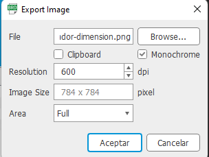
In the same way we must fill in the data of said image.
Checking the path of our file we will find a black image with the dimensions of the plate.
Tests
We must install Arduino IDE from the following link link: Arduino
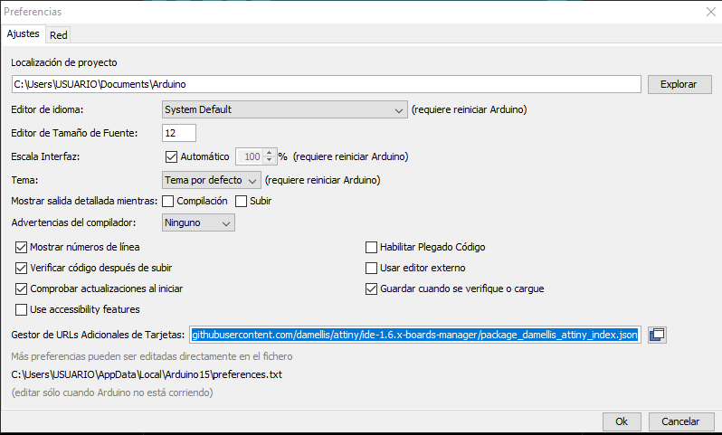
Open the Arduino IDE, select the option File > Preferences.

In Additional Card URLs Manager we add the following URL: Attiny ide1.6.x-boards manager
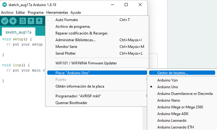
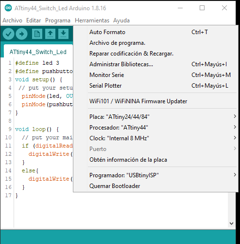
We open the card manager in Tools> Plate.
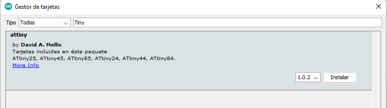
In the search engine we write Tiny and the option that appears from the author Dvid A. Mellis, we install it.
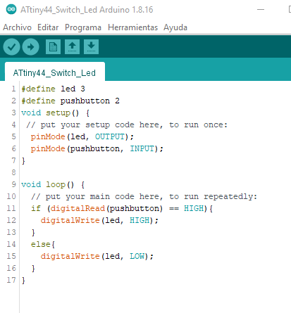
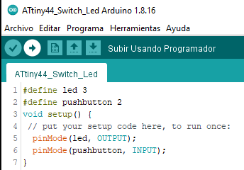
We write the following code, in the main work screen
We connect our plate with the led and the button to our programmer and the burner to our computer.
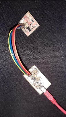
We press the button “Upload using the programmer”.
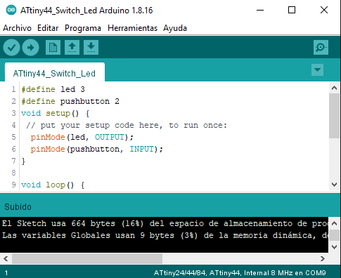
When the program is finished uploading, we will see the “Uploaded” message on the back.
We will use a breadboard to power our board with led and push button.

