7. Electronics design
This week we worked on electronics design.
Group Assignment
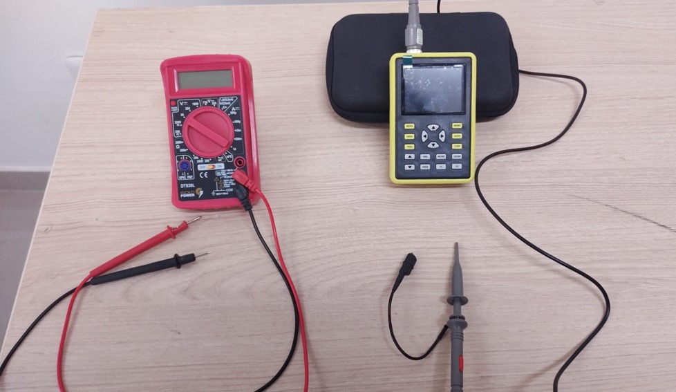
In the lab we have a multimeter and an oscilloscope:
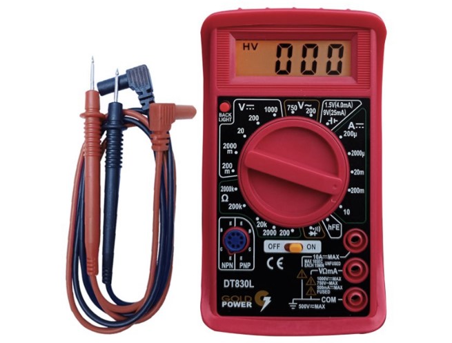
Digital Multimeter DT-830LRED GOLD POWER
This Digital Multimeter is an instrument that allows you to measure different electrical parameters and quantities in the same device. The DT-830LRED multimeter can measure AC and DC voltage, DC current, resistance and continuity and has the following features:
Specifications:
- DC Voltage (V): 200mV/2V/20V/200V/1000V
- AC Voltage (V): 200V/750V
- DC Current (A): 200µA/2000µA/20mA/200mA/10A
- Resistance (Ohm): 200Ohm/2kOhm/20kOhm/200kOhm/2MOhm
- Counter display: 1999
- Range selection: manual
- True RMS: no
- NCV: no
- Diode: yes
- Continuity buzzer: yes
- Transistor: yes
- Square wave output: no
- Data hold: no
- Auto off: no
- Low battery indicator: no
- Backlit display: yes
- Input impedance for DCV: about 10mohm
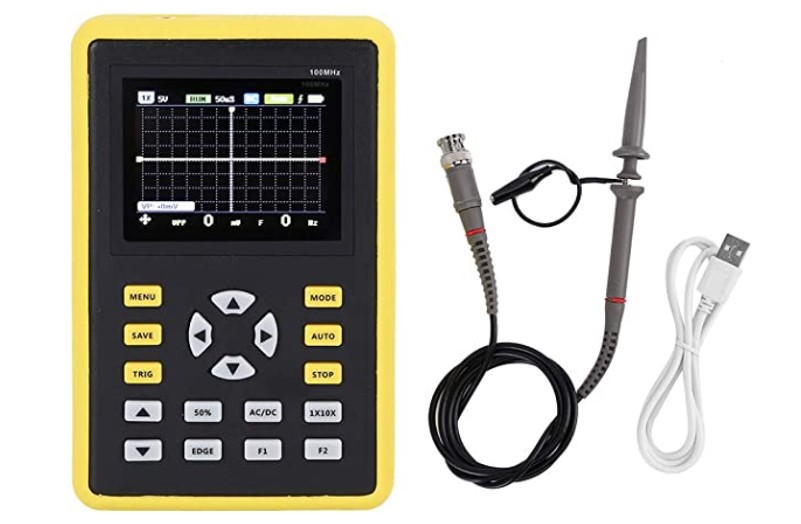
FNIRSI 5012H Digital Oscilloscope
This digital oscilloscope is portable with one channel with 100 MHz bandwidth, sampling rate 500 MS/s, equipped with 2.4” TFT LCD display and 3000 mAh lithium battery (up to 8 hours of autonomous work) and has the following features:
Specifications:
- Analogue bandwidth: 100MHz
- Maximum real time sampling rate: 500 MS/s
- Vertical sensitivity: 50 mV/div ~ 100 V/div
- Horizontal time range: 50S/div ~ 6nS/div
- Maximum test voltage: 80 V (1 probe), 800 V (10 probes).
- Storage depth: 128 kb
- Input resistance: 3.3 ft.
- ADC accuracy: 8 bits
- Coupling mode: AC/DC
- Trigger mode: single, normal, automatic
- Trigger edge: rising/falling edge
- External Trigger Voltage: 0-80V
- Display: 2.4 inches-320 x 240-IPS process
- Power source: 5000 mAh lithium battery
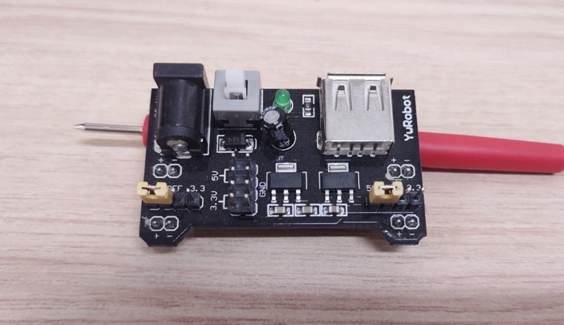
To learn how to use the multimeter we use the Ams1117 Power Mb V2 Protoboard Power Supply Module (Output 5 Volts AND 3.3 Volts) that we have in the lab
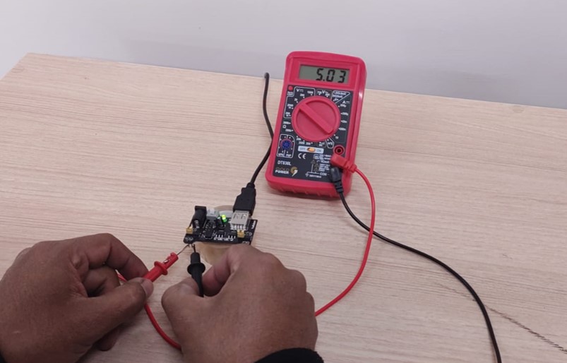
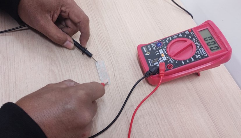
We must select the unit to measure, in our case we will measure the 5 volts of the module, for this we must first place the measurement probes in the multimeter, the red probe we will put it in the output with the label V, and the black probe we will put it in the output with the label COM. Then we must move the main knob to the unit we want to measure, we must select a higher unit than the one we are looking for, in this case 20V. The probe tips are placed on the pins and you will get a reading of 5.03 V on the multimeter display which means you have 5 volts.
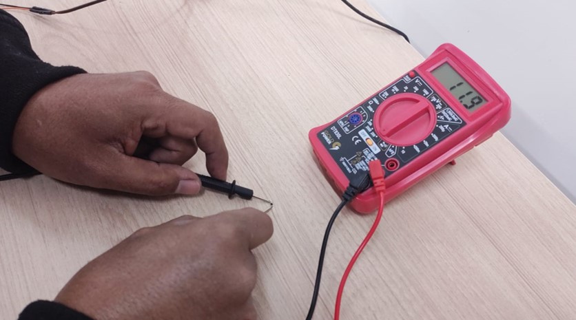
You can also measure the ohm rating of a resistor. To do this we change the voltages to ohms and since the resistance is 10, we put the nearest measurement, in this case 200. When we place the test leads on both ends of the resistor, the value of 11.9 ohms is displayed on the screen. Measurements are never exact.
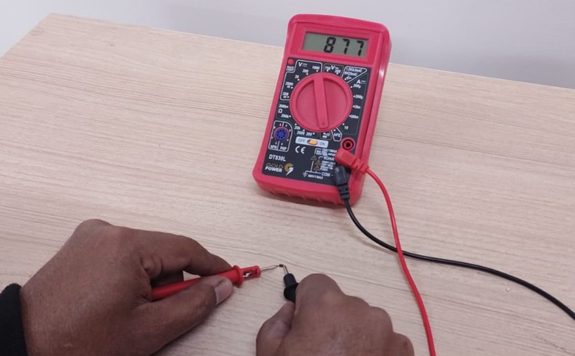
Another value that can be measured is the capacitance of the diodes. You switch the measurements to Continuity (this category is represented by the figure of a diode) and measure the diode values giving you a reading of 877 millivolts.
Finally, the multimeter allowed us to know the continuity of the tracks of a board we milled in the lab. The measurement is switched to Continuity and when the test leads are placed at two far ends of a track, a beep is heard and a value of 000 is displayed which means that there is continuity.
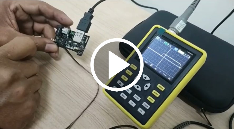
To learn how to use the Oscilloscope we must first place the probe on the back of the oscilloscope. then we must turn on the oscilloscope with the switch on the bottom of the oscilloscope. To change the frequency we press the left and right arrows, in our case we will press the left arrow until we reach 1s (1 second), we will press the up and down arrows to select the voltage, in our case we will press the up arrow until we reach 5V (5 volts). Then place the test leads on the voltage output pins of the Power Mb V2 Ams1117 Protoboard Power Supply Module. We turn on the module and a voltage signal is displayed graphically.
On the oscilloscope screen we can see the yellow signal emitted by the AMS1117 module, this module has a push button that will allow us to generate a digital signal. When we press the button, the AMS1117 module emits a 5v signal and when we press the button again, a 0v signal is emitted. On the oscilloscope screen we can observe the digital signal generated by pressing the button on the AMS1117 module over a range of time.
Individual Assignment
For my individual assignment I decided to fabricate a board with the microcontroller available in my lab: ATtiny44.
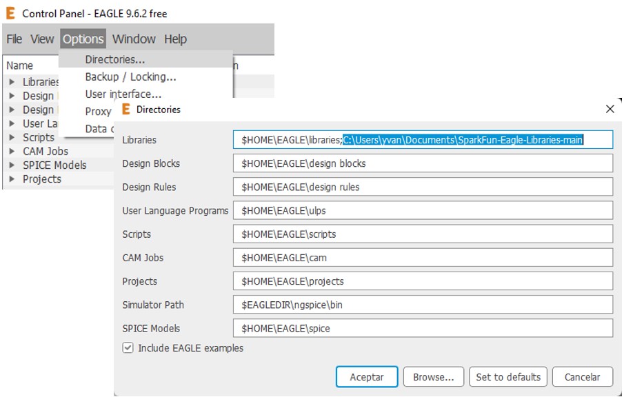
The Eagle software was used again. Before performing any operation I added the SparkFun-Eagle library as follows:
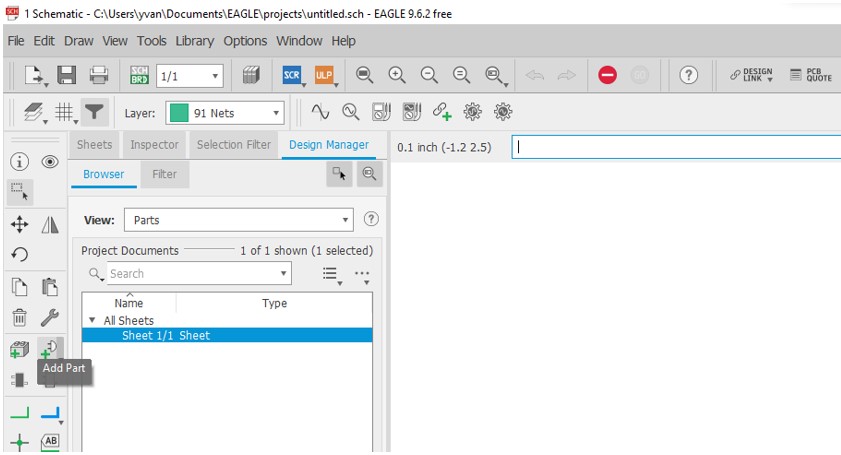
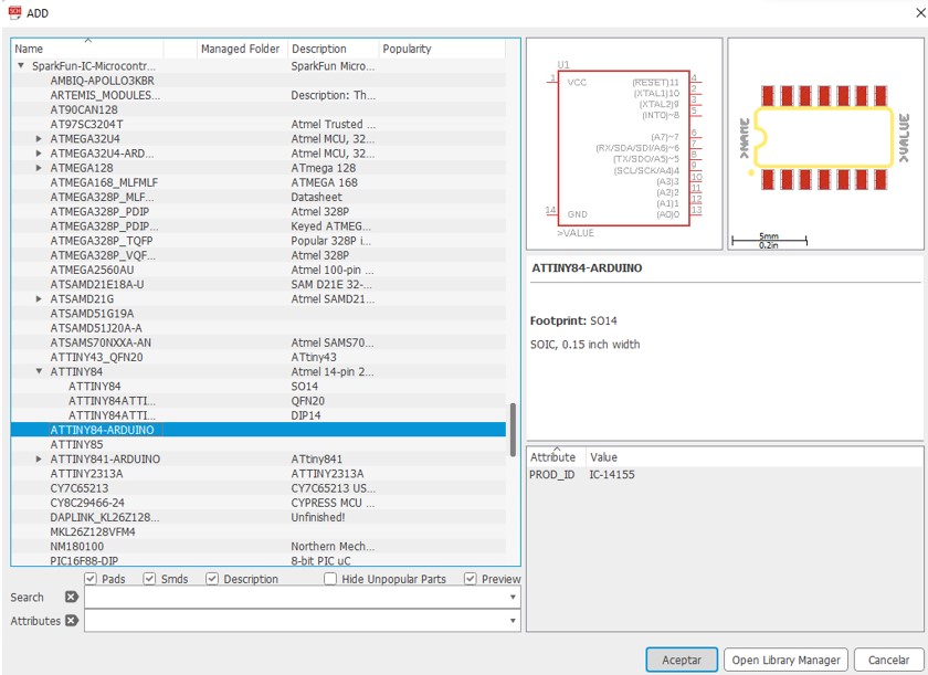
Once in the Schematic I started to add the components in the left bar: “Add part”.
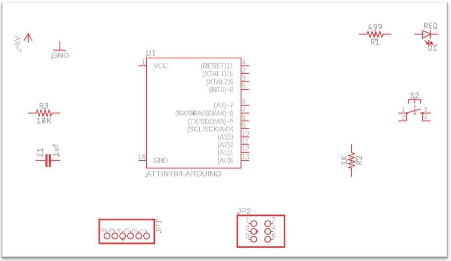
The ATtiny44 microcontroller found in the “Sparkfun-IC-Microcontroller” library was added, with the name “ATTINY84-ARDUINO”.
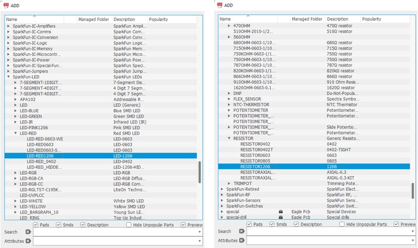
An LED was also added: LED-RED1206 and three resistors RESISTOR1206.
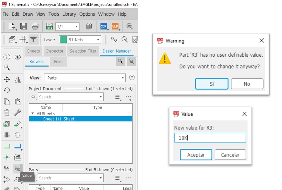
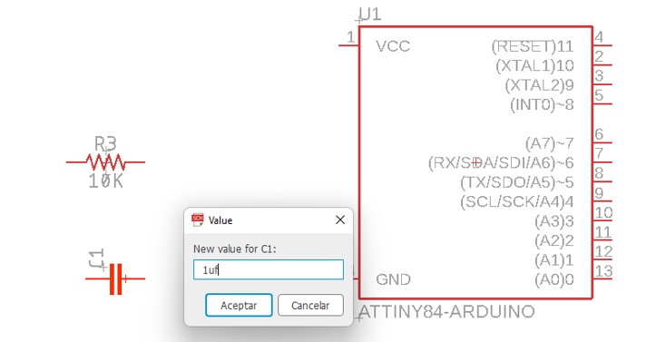
The inserted resistors do not have an added value, so each value must be added manually. To do this, choose the “Value” option in the left-hand toolbar.
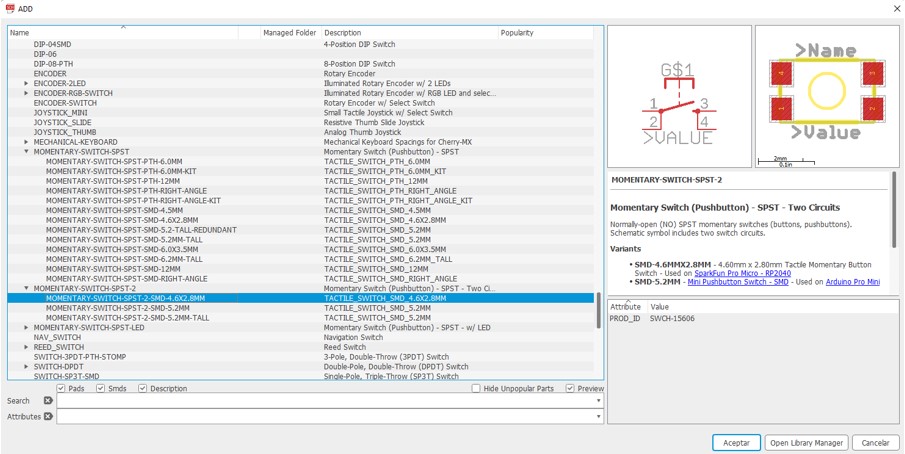
Then the switch was added from the MOMENTARY-SWITCH-SPST-SMD-2-4.6x2.8MM library.
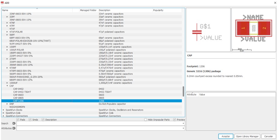
A capacitor CAP-1206.
To which we added the value of 1uf.
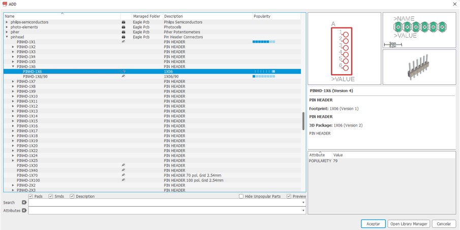
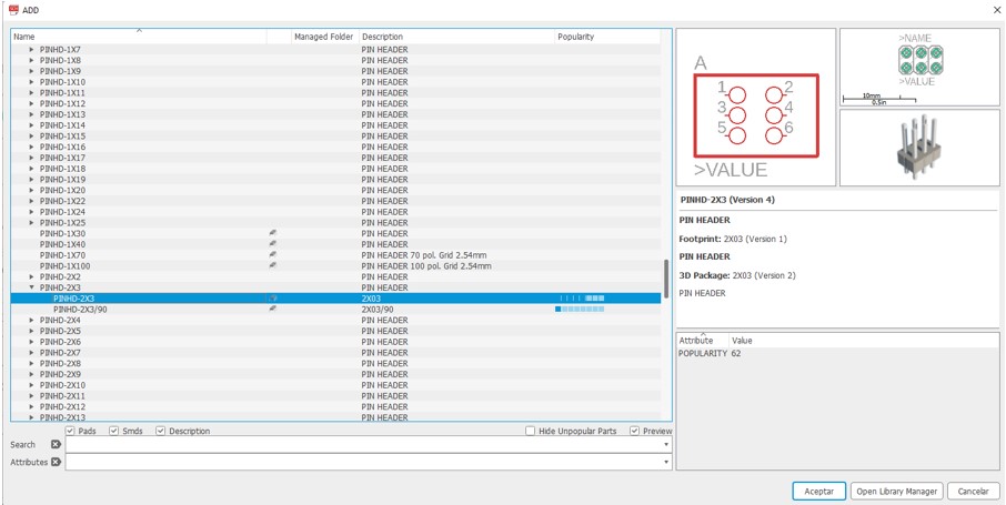
Finally, we added 6X1 “PINHD-1X6” and 6X2 “PINHD2X3” spinners.
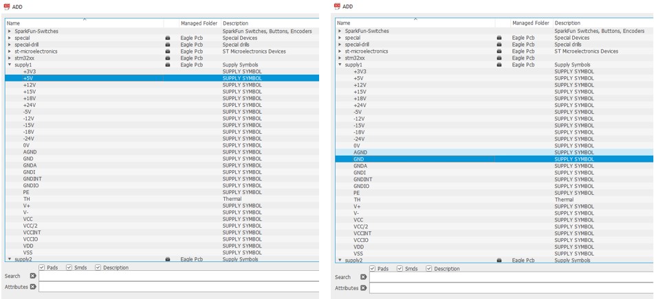
We added the 5 volt signal from “supply1”, with the name “+5V” and we also added the ground signal from “supply1”, with the name “GND”.
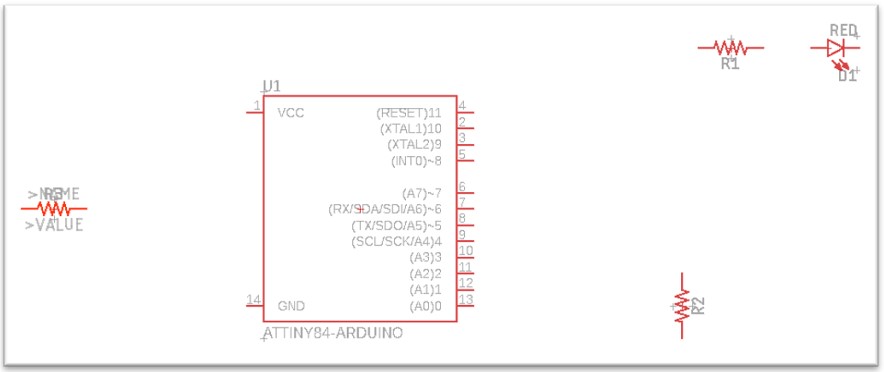
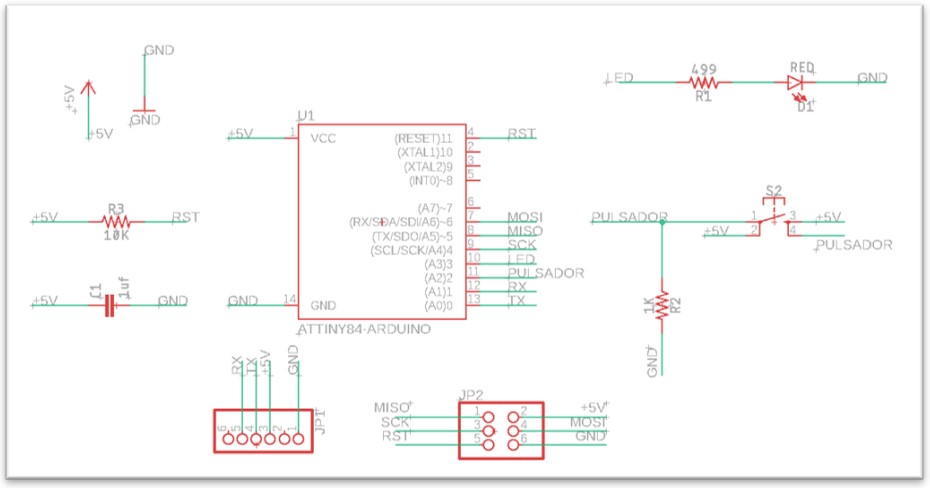
The schematic worksheet will look like this:
After adding the components we continue with the connections between components with the “Net” tool.

We add names to the signals with the “Label” tool. To add a name we just click on the green line we need to name and Eagle will automatically create a name, we will have to choose the position of the name by moving the mouse and if necessary by pressing the right button to rotate the name.
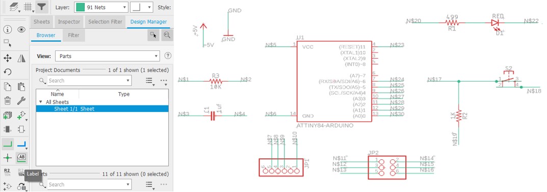
Finally, we change the names of the signals we added with the “Name” tool.
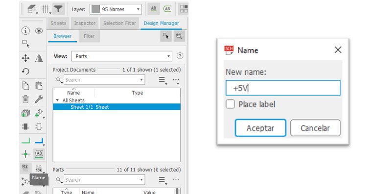
We will have to modify all the signals in the following way:
Designing the PCB board
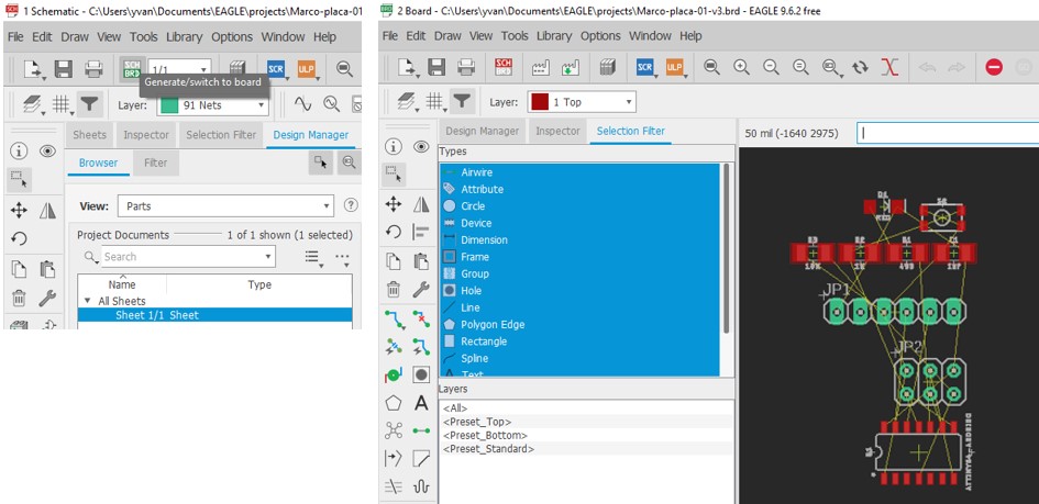
To create the PCB board from the schematic, click on the “Generate/switch to board” button to create the PCB board.
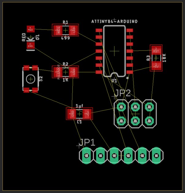
After creating the PCB board we use the “Move” tool to move the components to the intense black box where we can edit the border with the “Polygon” tool so that it ends up like this:
To draw the routes on the PCB we use the “autorouter” tool and the “Tools” option. To use it you must first define the design rules. The definition of the autorouter design rules can be found in Tools: DRC.
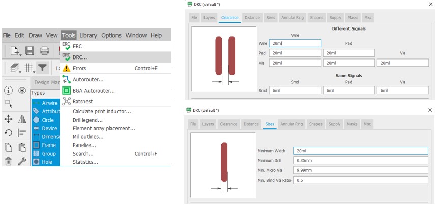
Then select the Tools: Autorouter option.
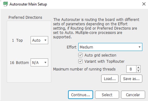
Then press “Continue” and Eagle will calculate the necessary tracks automatically. The result is as follows:
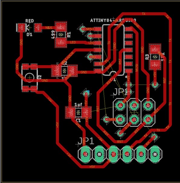
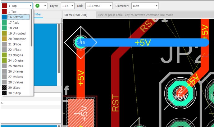
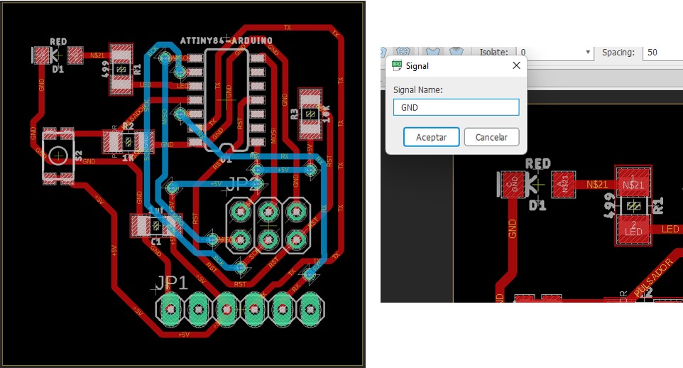
The automatic option often does not complete all tracks as you can see in the picture above (thin yellow lines). In this case bridges have to be created on the back side of the board. For this purpose, routes are created and switched to the “Bottom” layer (blue).
After all the bridges have been drawn, the board ends up as shown in the picture. When we finish selecting the board a dialog box will appear asking for the name of the signal we want to connect to, we put the name GND.
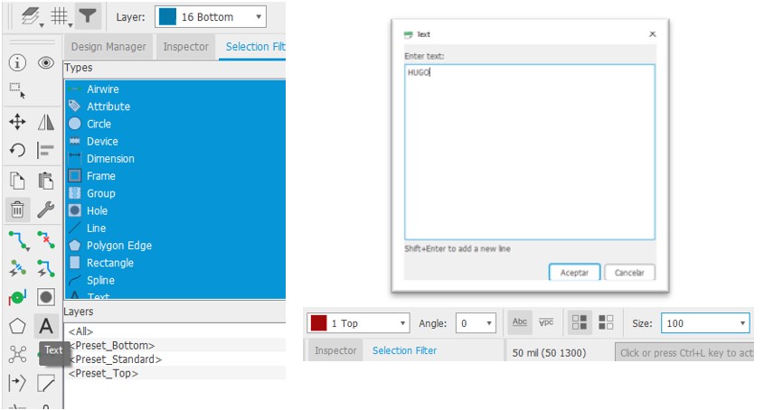
To personalise the board with my name, use the “Text” tool, place the text on the “Top” layer and give it size 100.
After adding the text we use the “Rastnet” tool and generate the GND layer.
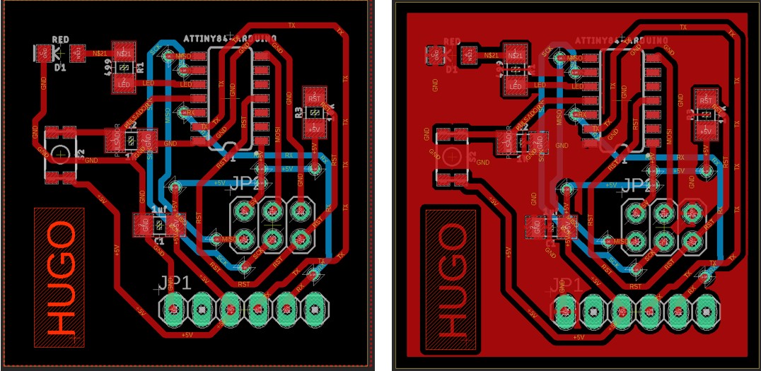
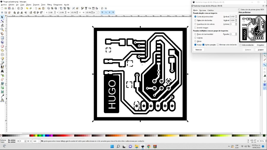
To export the file as a .png image, proceed as in the “Electronic Production” task. The image ends up like this. The border of the board, which is in the “Dimension” layer, must also be exported.
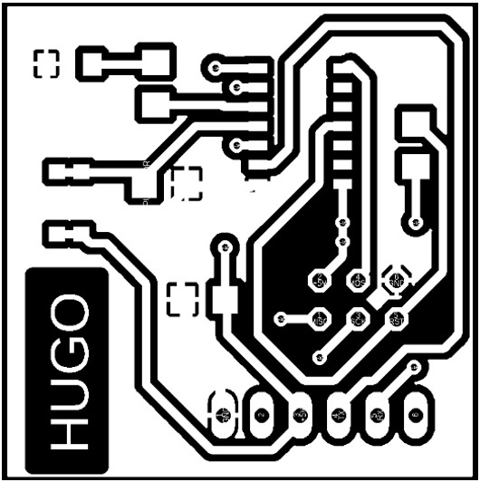
We exported the .png images as done in task 5 electronics production.
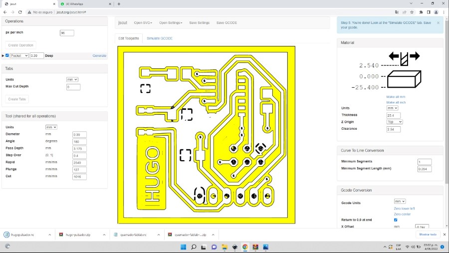
The inkscape software helped us to vectorise and the jscut software to set the milling parameters.
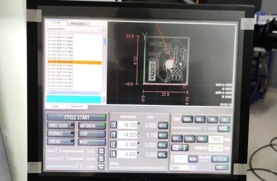
Finally the G-code was taken to our Tormach CNC for milling the board.
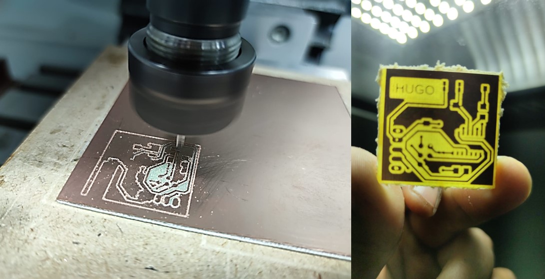
After soldering every component on the board, here is the final result:

The Arduino IDE was used to carry out the tests.
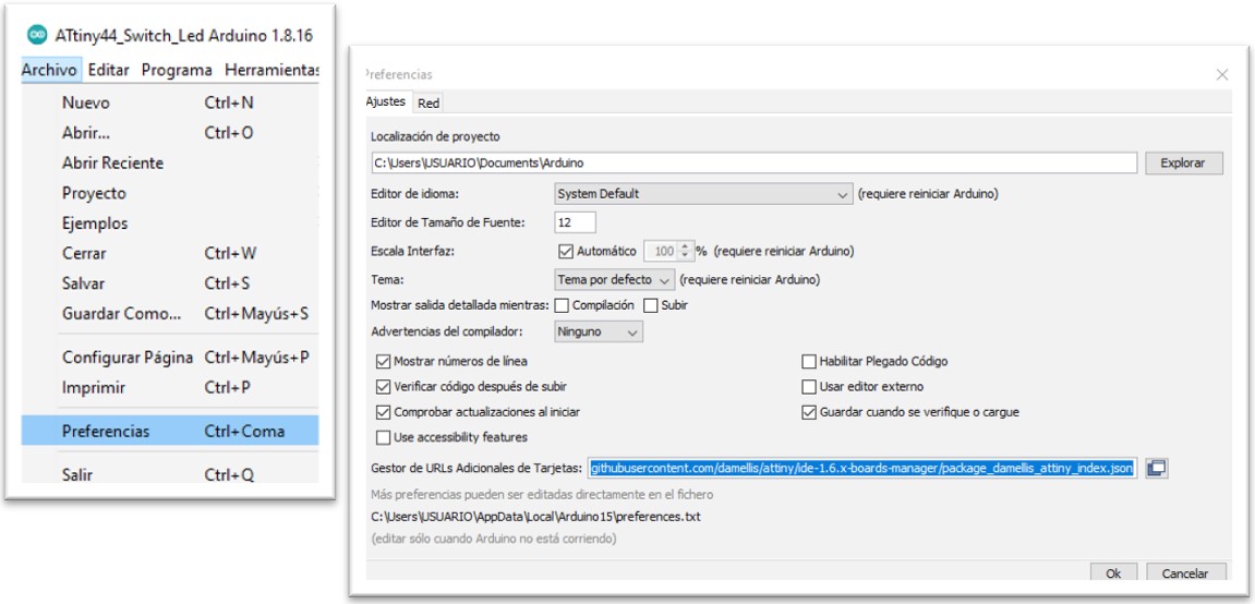
After opening the Arduino IDE, search in Preferences for the option “Additional Card URLs Manager” where the following URL is added:
https://raw.githubusercontent.com/damellis/attiny/ide-1.6.x-boards-manager/package_damellis_attiny_index.json
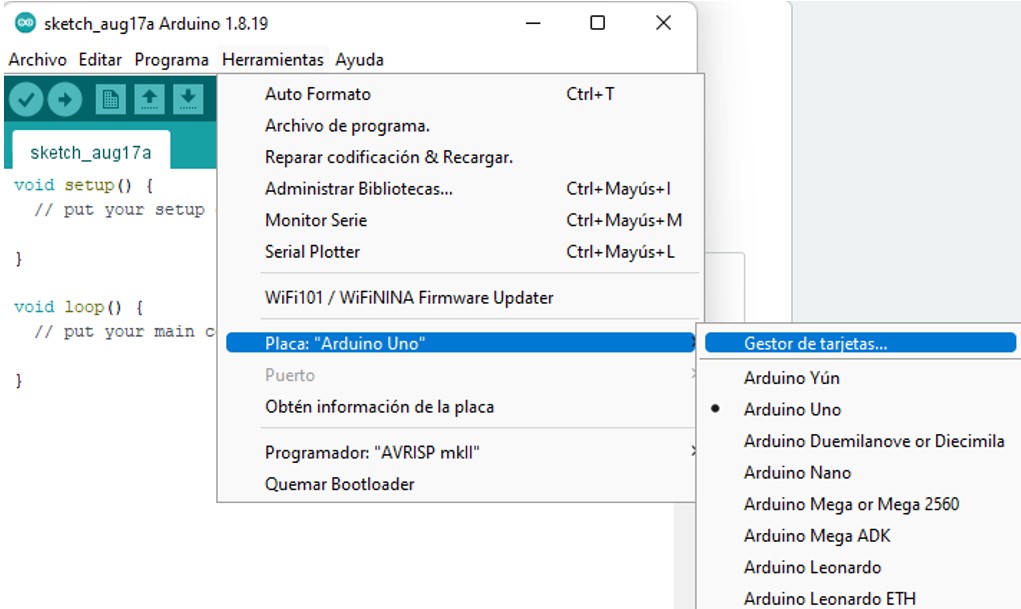
Then, in the Tools menu, search for the option Board: “Arduino Uno” and open the Board Manager.
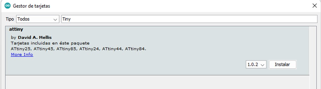
In the search engine write “tiny” and then install the option that appears from the author David A. Mellis.
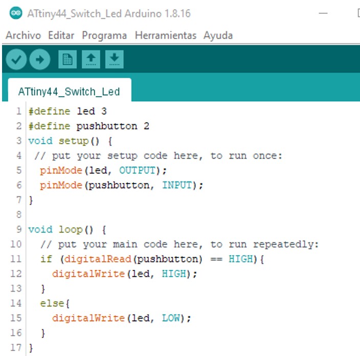
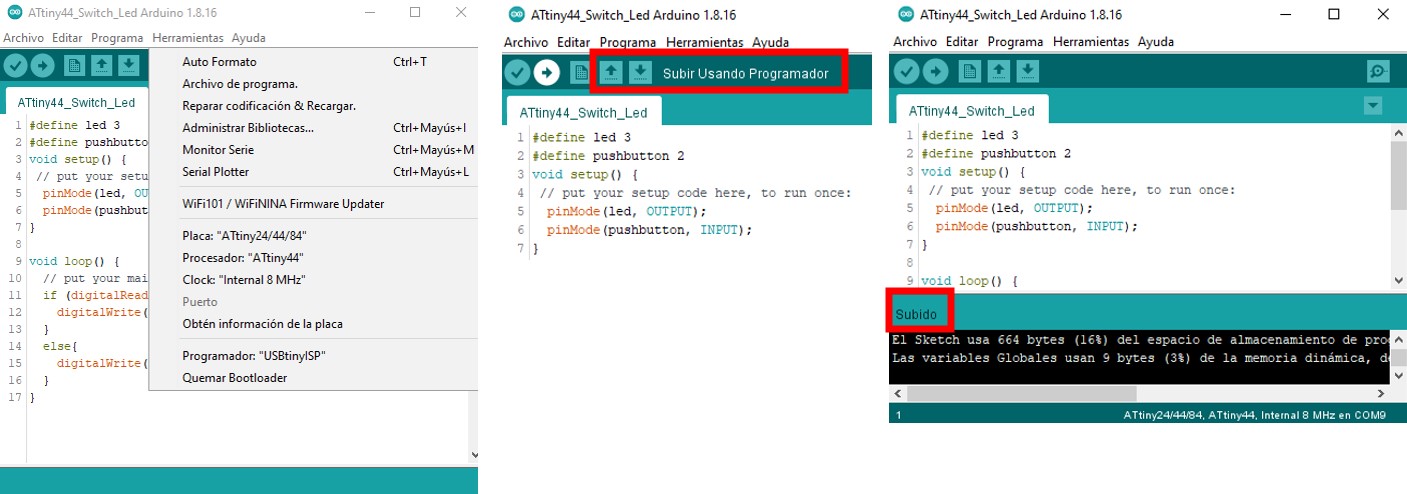
Write the following code on the main work screen:
We connect our board with the led and the push button to our programmer and the burner to our computer.
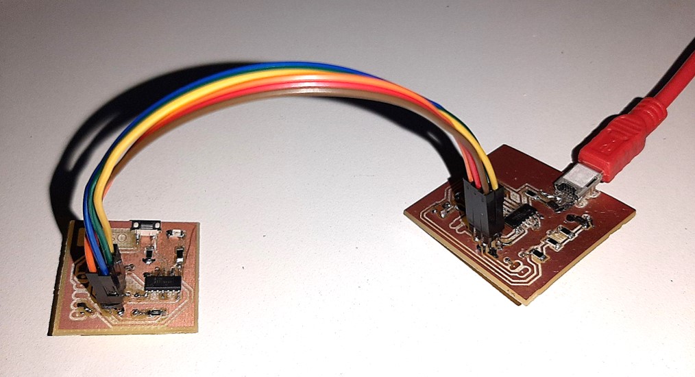
We press the button “Upload using the programmer”.
When the program is finished uploading, we will see the “Uploaded” message on the back.
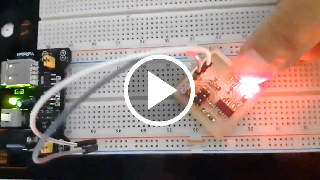
 We will use a breadboard to power our board with led and pushbutton.
Here it is the operation of the button and the led light.