9. Embedded programming
This week I worked on embedded programming
Group Assignment
RASPBERRY PI PICO
The Raspberry Pi Pico series is a range of tiny, fast and versatile boards built with RP2040. Programmable in C and MicroPython, Pico accommodates a wide range of applications and skill levels, and getting started is as easy as dragging and dropping a file. More experienced users can take advantage of Raspberry Pi Pico’s rich set of peripherals, including SPI, I2C, and eight programmable I/O (PIO) state machines for custom peripheral support.
RP2040
Designed by Raspberry Pi, the RP2040 features a dual-core Arm Cortex-M0+ processor with 264kB of internal RAM and support for up to 16MB of off-chip flash. A wide range of flexible I/O options includes I2C, SPI, and - uniquely - programmable I/O (PIO).
To program the RP Pico we can follow the information found at the following link: https://www.raspberrypi.com/documentation/microcontrollers/
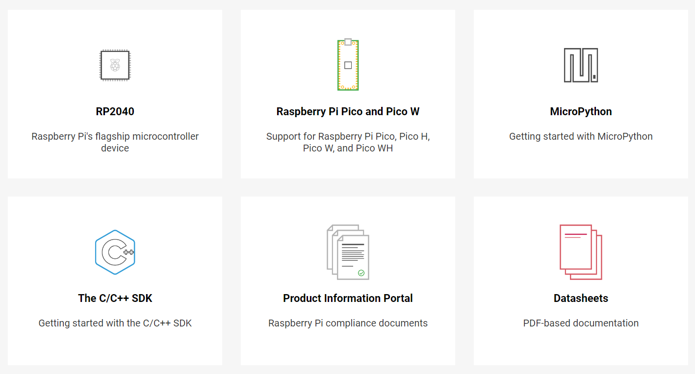
Select the MicroPython option.
Download the MicroPython UF2 file compatible with the version of our RP Pico. https://micropython.org/download/rp2-pico/rp2-pico-latest.uf2
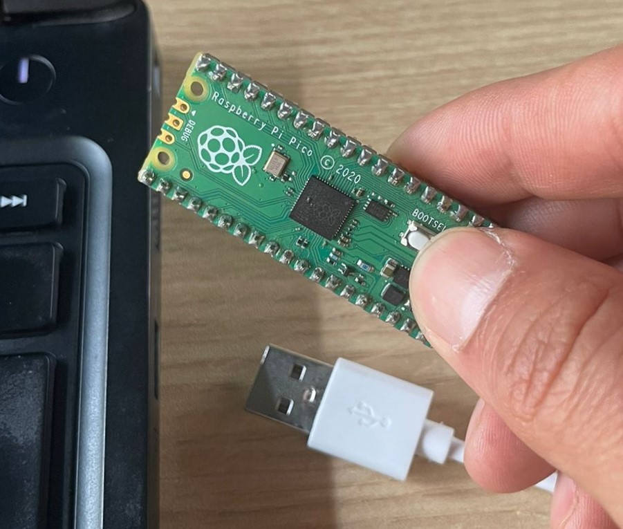
While holding down the BOOTSEL button, we connect our RP Pico to the computer via the USB port. Once connected, release the BOOTSEL button.
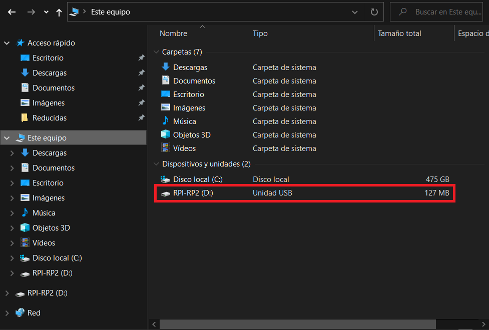
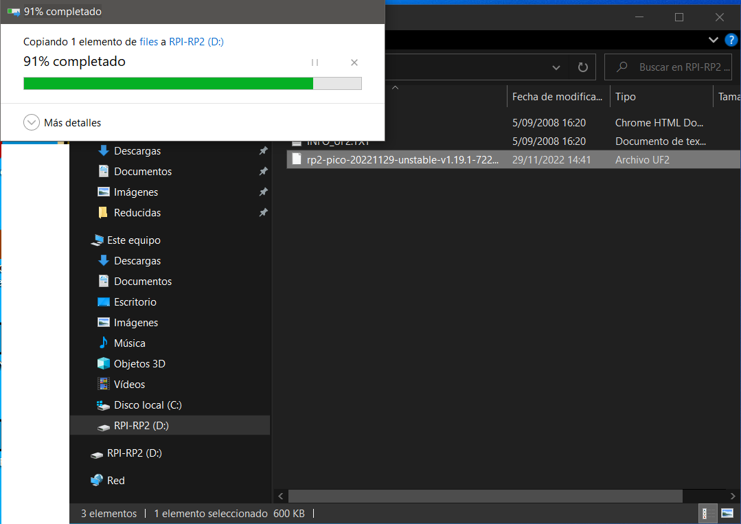
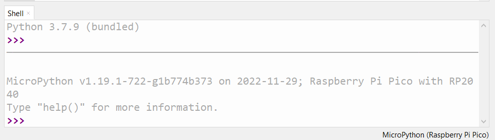
Open the RPI-RP2 folder and copy the previously downloaded file and the RP Pico will restart and MicroPython will be running.
Now we download and install the IDE Thony software from the following link: https://thonny.org/
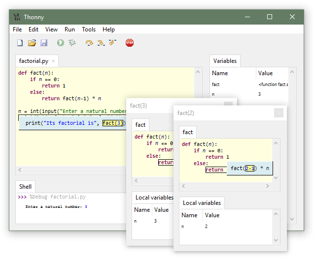
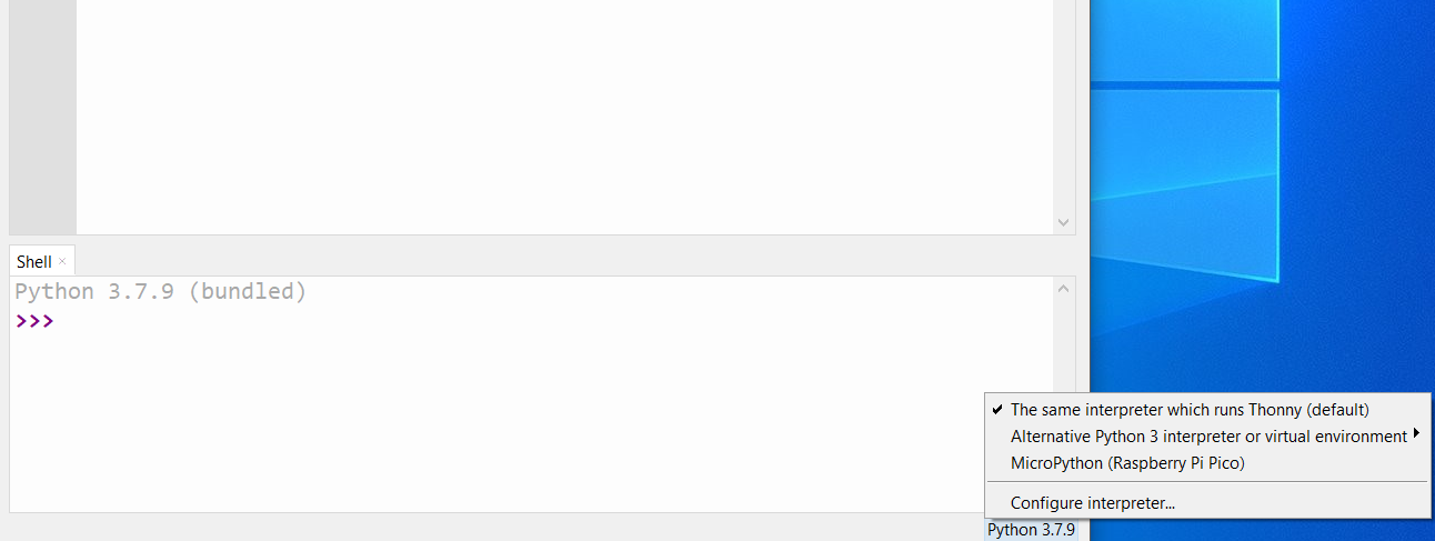
At the bottom left we can choose where we want the code to run. We will choose the option MIcroPython (Raspberry Pi Pico).
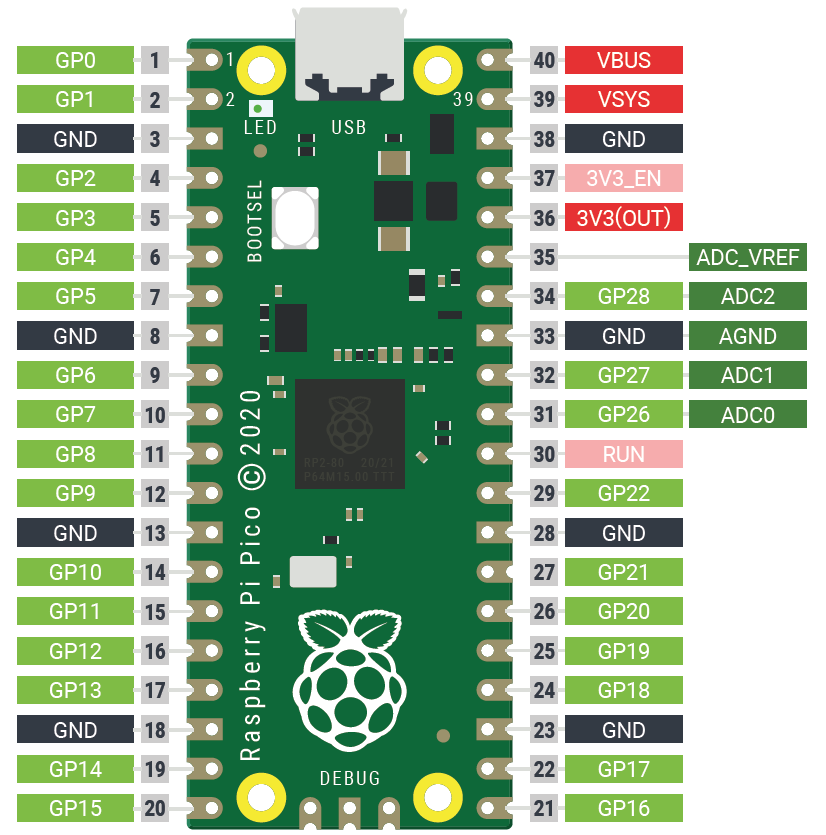
Pinout of the Raspberry Pi Pico
We assemble the following circuit
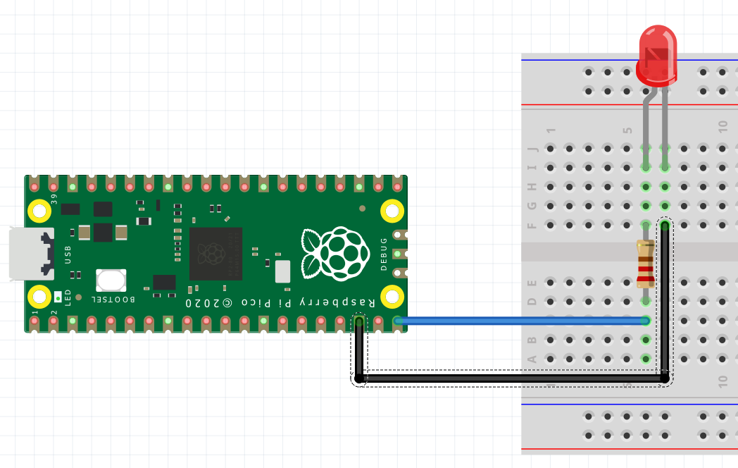
We run the following code and it will ask us where to save it, we will choose in the Raspberry Pi Pico
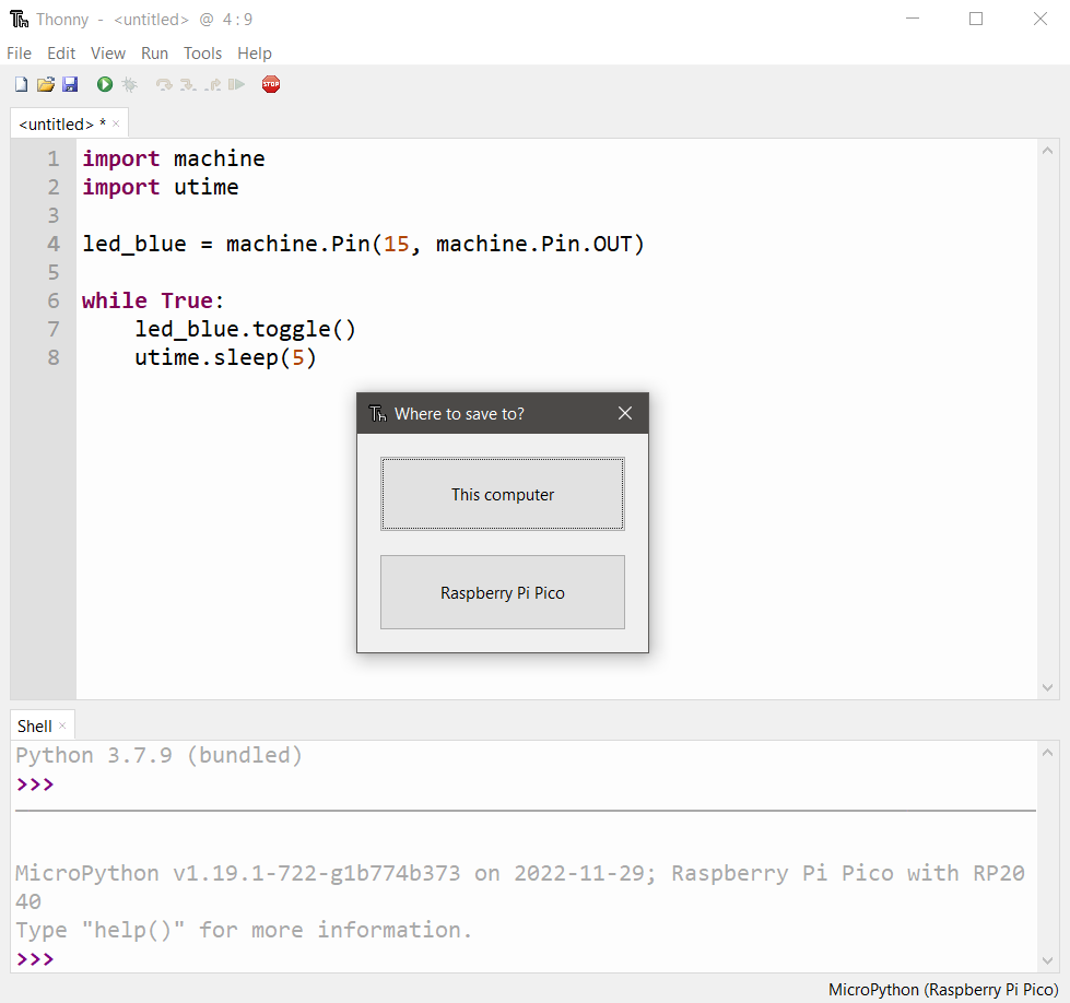
Code:
import machine import utime
led_blue = machine.Pin(15, machine.Pin.OUT)
while true: led_blue.toggle(). utime.sleep(1)
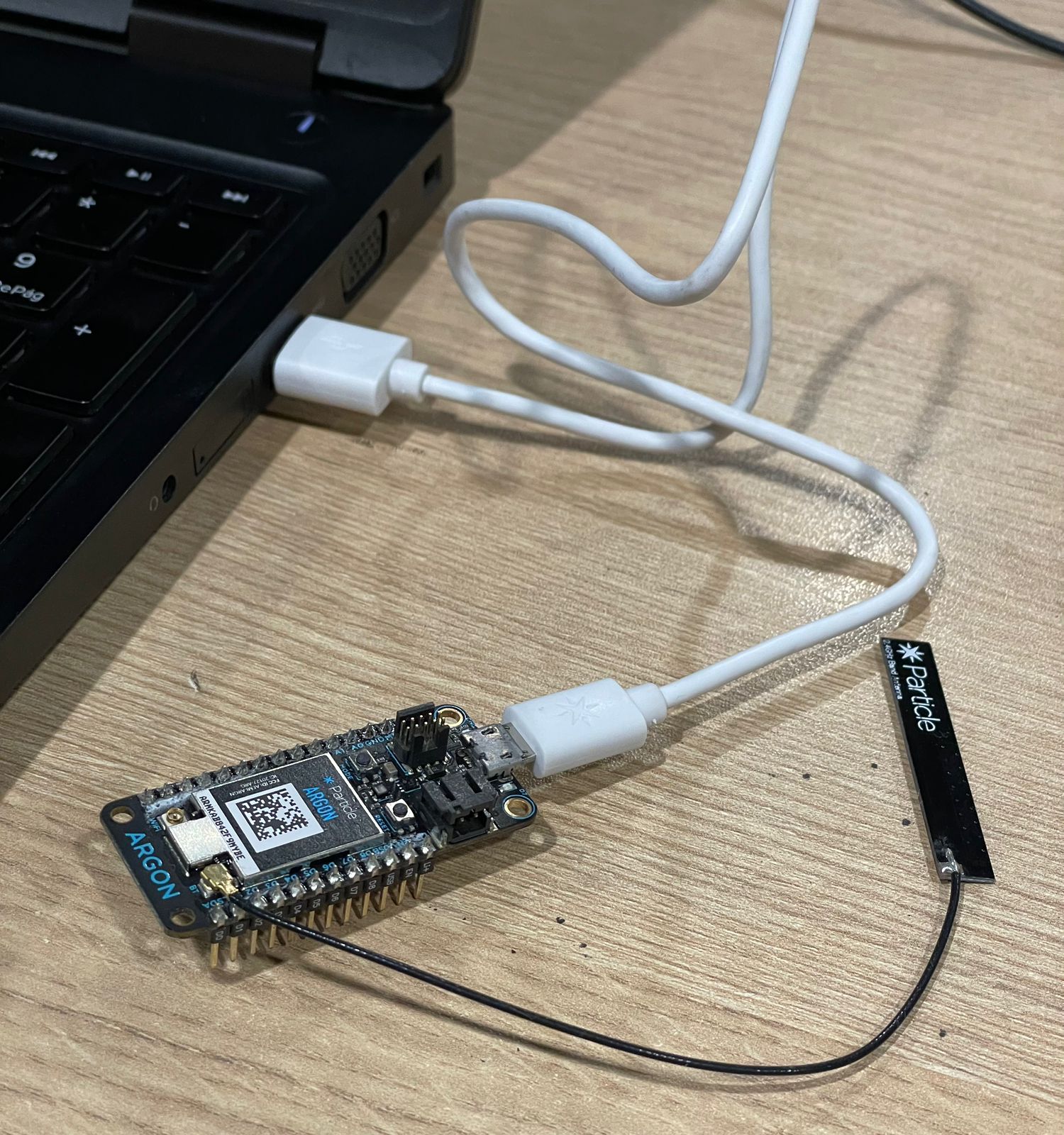
ARGON PARTICLE The Argon is a powerful Wi-Fi enabled development board for Wi-Fi networks. It is based on the Nordic nRF52840 and has built-in battery charging circuitry.
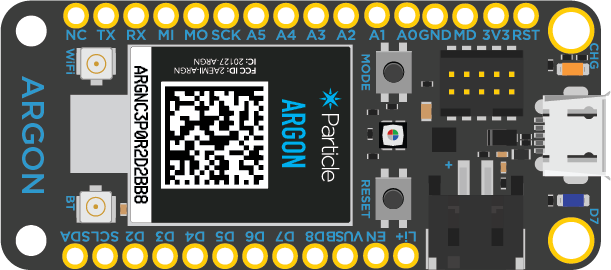
Features - Espressif ESP32-D0WD 2.4 GHz Wi-Fi coprocessor
  On-board 4MB flash for ESP32
  802.11 b/g/n support
  802.11 n (2.4 GHz), up to 150 Mbps
-
Nordic Semiconductor nRF52840 SoC
ARM Cortex-M4F 32-bit processor @ 64MHz 1MB flash, 256KB RAM Bluetooth 5: 2 Mbps, 1 Mbps, 500 Kbps, 125 Kbps Supports DSP instructions, HW accelerated Floating Point Unit (FPU) and encryption functions Up to +8 dBm TX power (down to -20 dBm in 4 dB steps) NFC-A tag - On-board additional 4MB SPI flash - 20 mixed signal GPIO (6 x Analog, 8 x PWM), UART, I2C, SPI - Micro USB 2.0 full speed (12 Mbps) - Integrated Li-Po charging and battery connector - JTAG (SWD) connector - RGB status LED - Reset and Mode buttons - On-board PCB antenna - U.FL connector for external antenna - Meets the Adafruit Feather specification in dimensions and pinout - FCC, CE and IC certified - RoHS compliant (lead-free)
To start programming this board we can follow the tutorial at the following link: https://docs.particle.io/quickstart/argon/
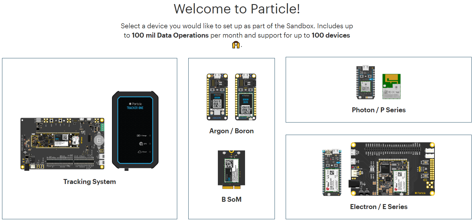
Procedure: We enter the Particle configuration page: https://setup.particle.io/
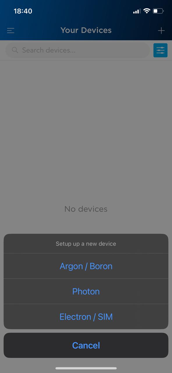
Choose the Argon / Boron option
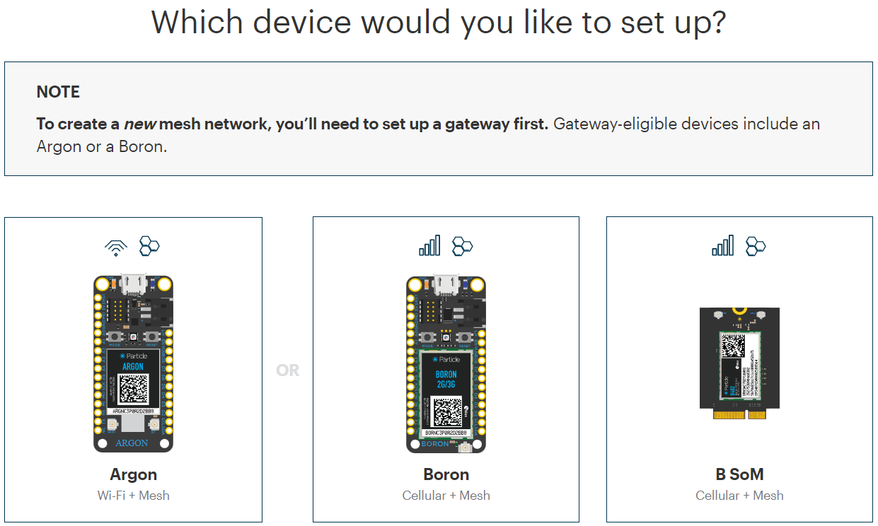
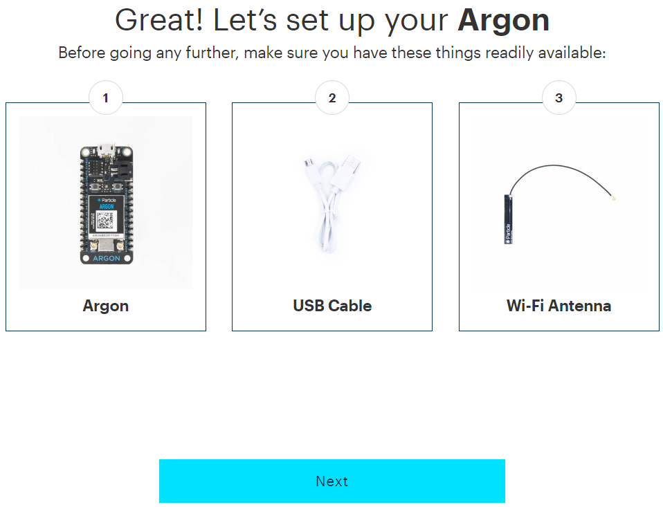
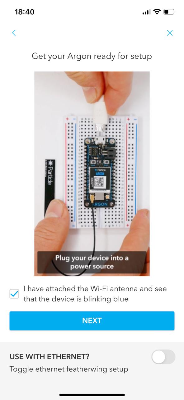
Choose the Argon option and press Next
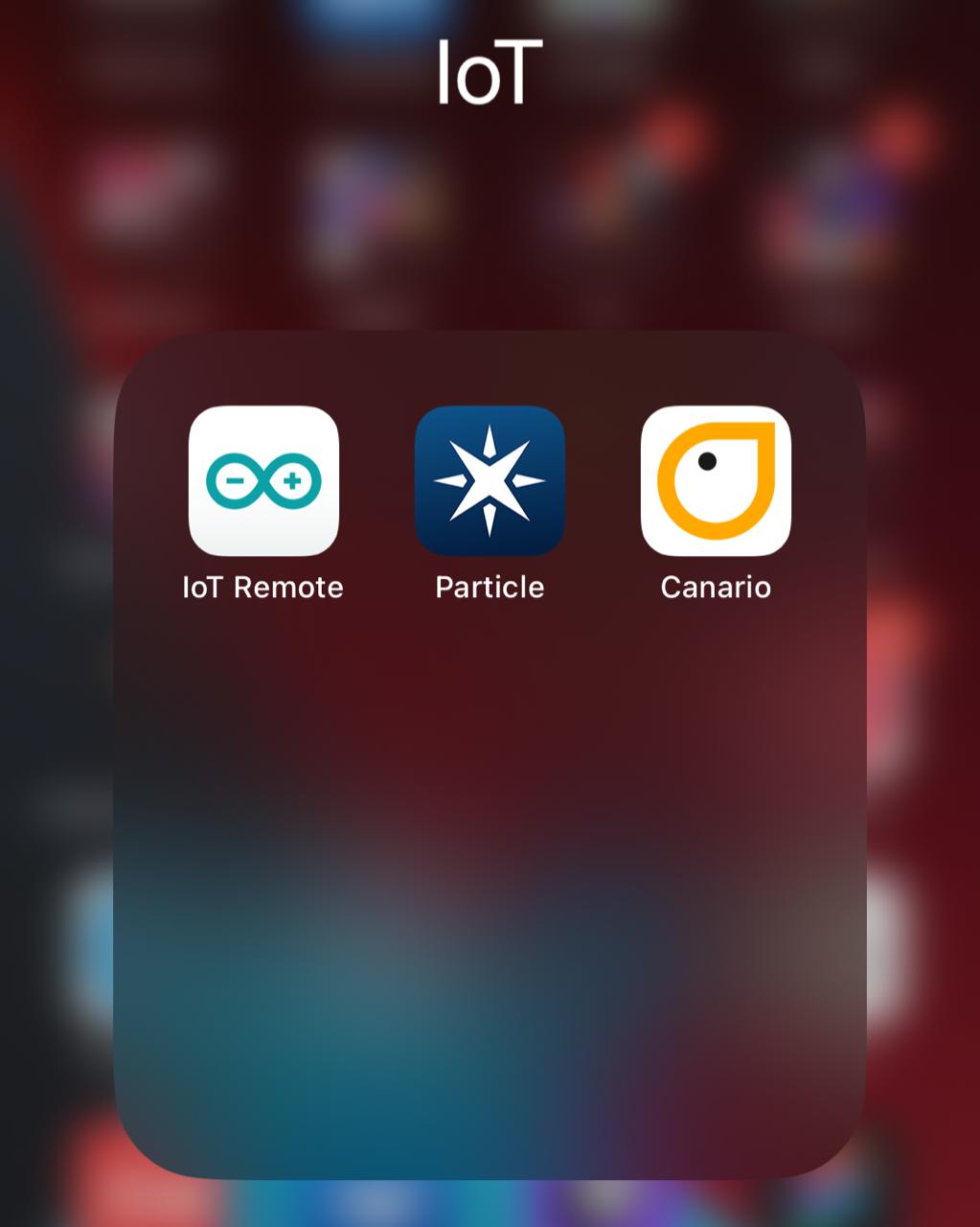
Now we have to install the Particle App from the iOS or Android store. For iOS follow this link: https://apps.apple.com/us/app/particle-iot/id991459054
Open the App and log in
We connect the board to the computer through the USB port
Setup a new device
Connect the antenna to the board
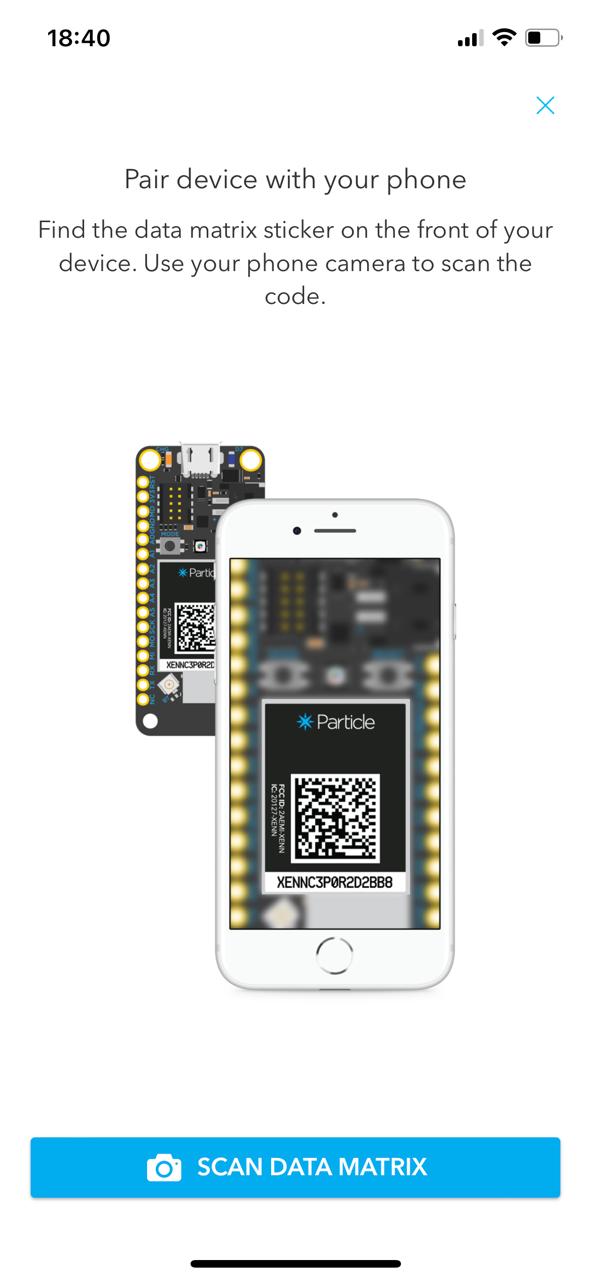
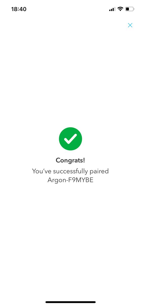
Scan the QR code on top of the board and wait for the device to finish pairing with the cell phone.
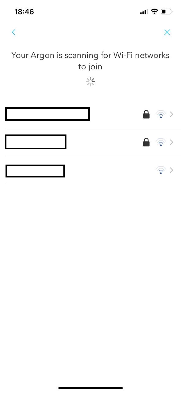
Select a wireless network and log in.
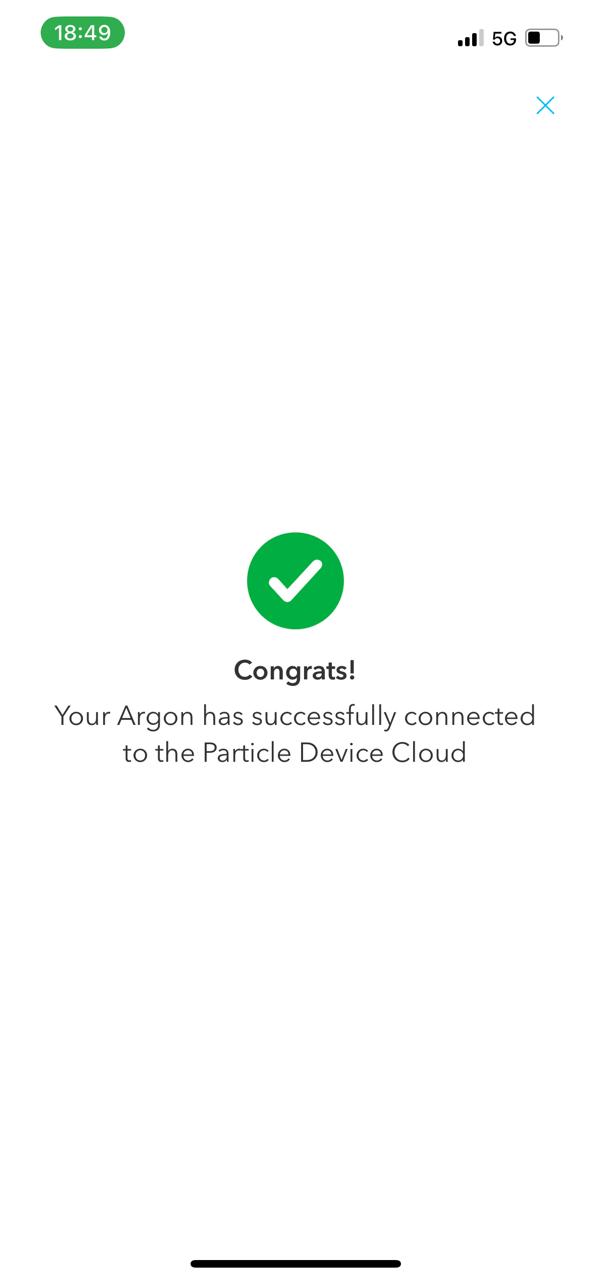
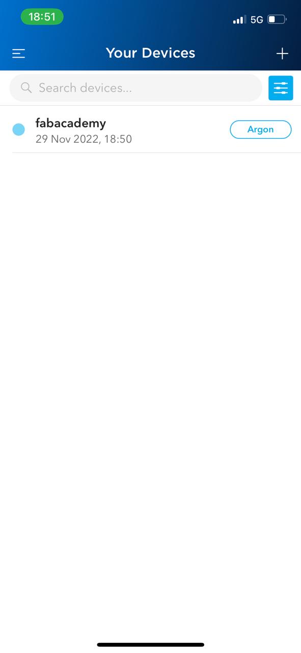
After connecting to the wireless network, we assign a name to the device
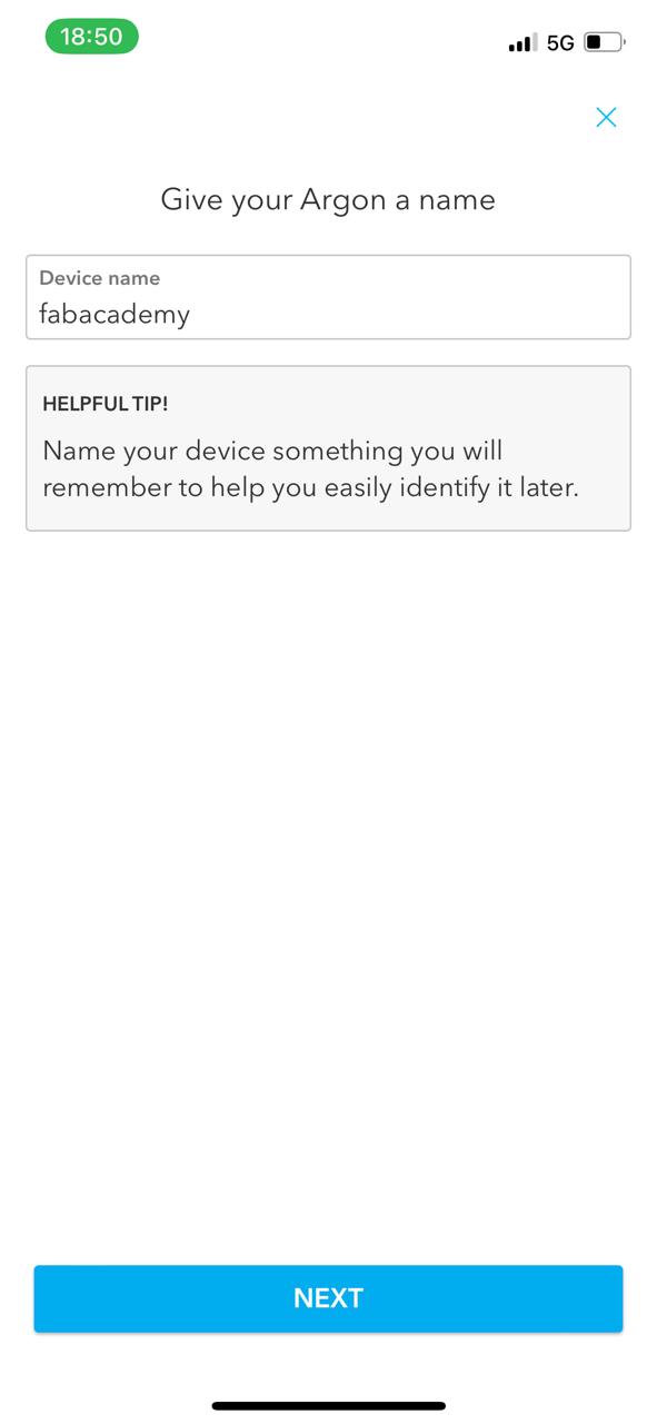
Select the new device
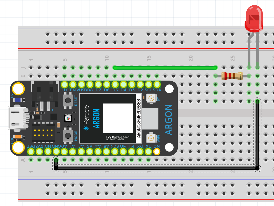
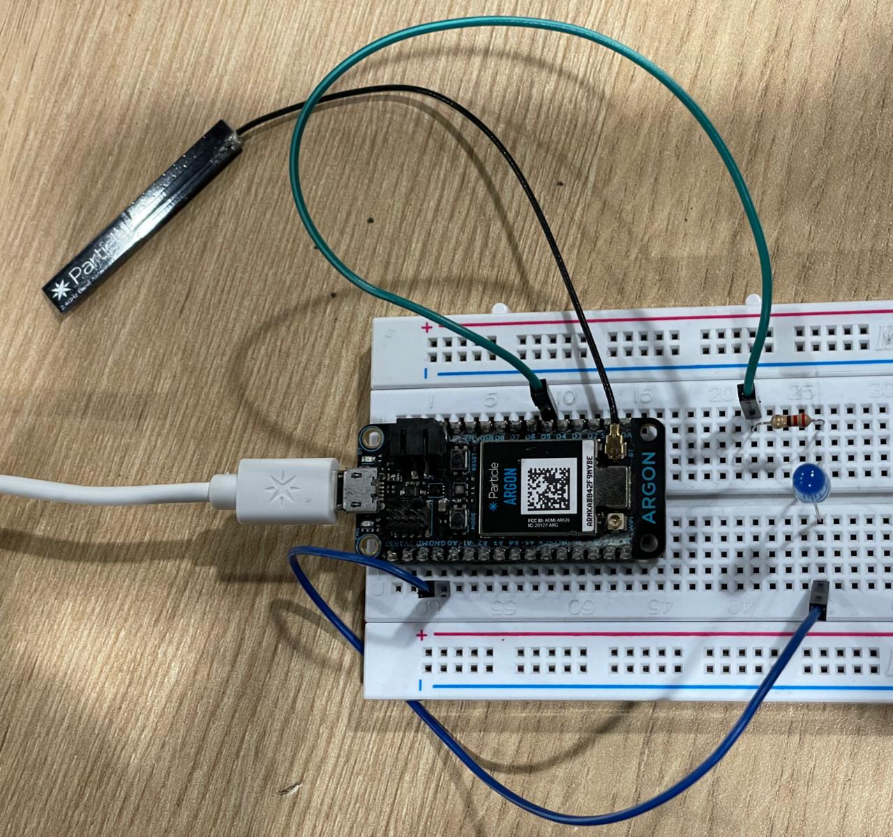
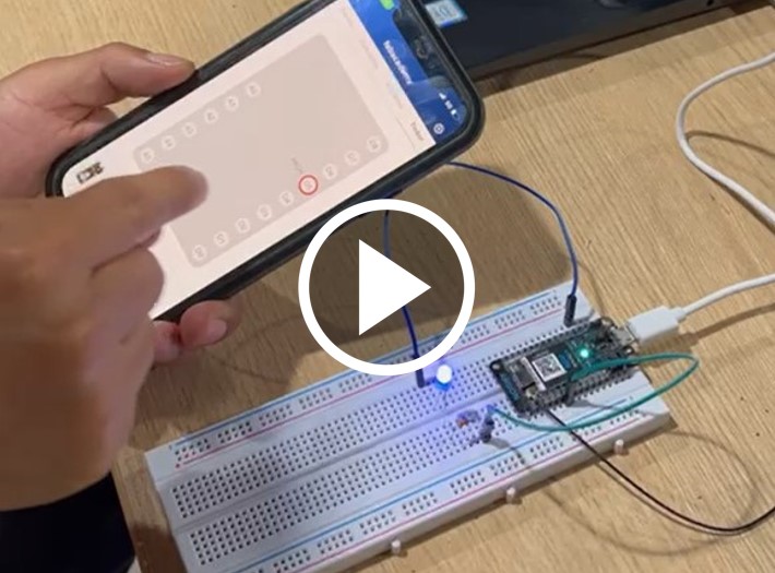
We set up the following circuit
Go to the Tinker tab and it will show us the input and output pins of the board. Click on D5 and configure it with digitalWrite.
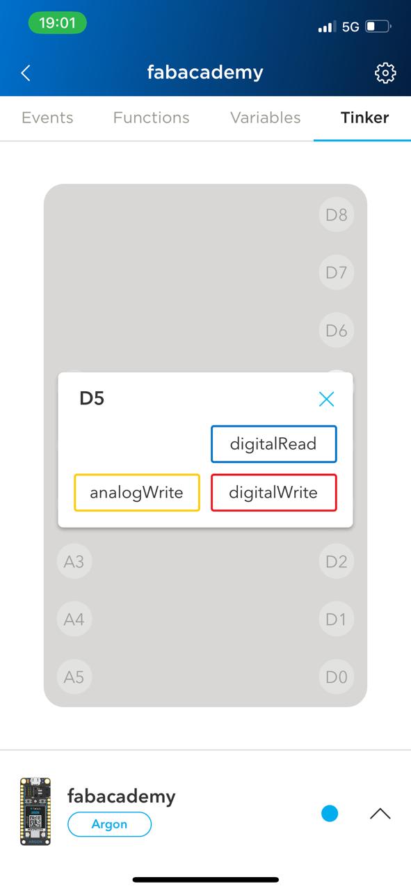
Finally, click on D5 and the LED will turn on. We press again on D5 and this time the LED will turn off.
Individual Assignment
For this assigment I am going to modify the PCB that can be found at The Fab Academy 2022 Schedule.
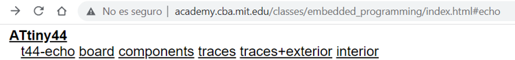
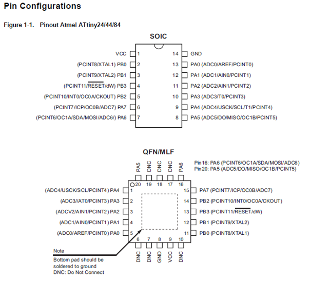
This PCB is based on the ATtiny44 microcontroller of the ATMEL family.
According to its datasheet that we can download from microchip
Its main features are: - Advanced RISC architecture - 2/4/8K byte of in-system programmable program memory flash (Atmel®) - ATtiny24/44/84) - 128/256/512 bytes in-system programmable EEPROM (Atmel ATtiny24/44/84) - 128/256/512 bytes internal SRAM (Atmel ATtiny24/44/84) - 10-bit ADC - 12 differential ADC channel pairs with programmable gain (1x, 20x) - Universal serial interface - In-system programmable via SPI port - Operating voltage: 2.7 - 5.5V for Atmel ATtiny24/44/84 - Low power consumption
Pin compatibility with Arduino is as follows:
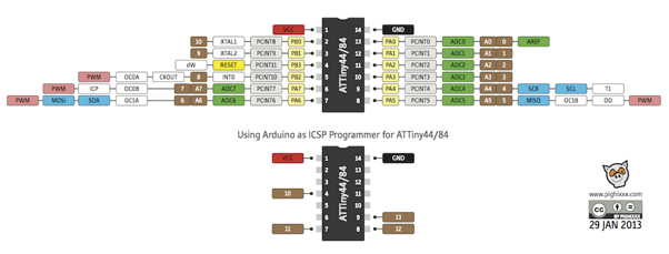
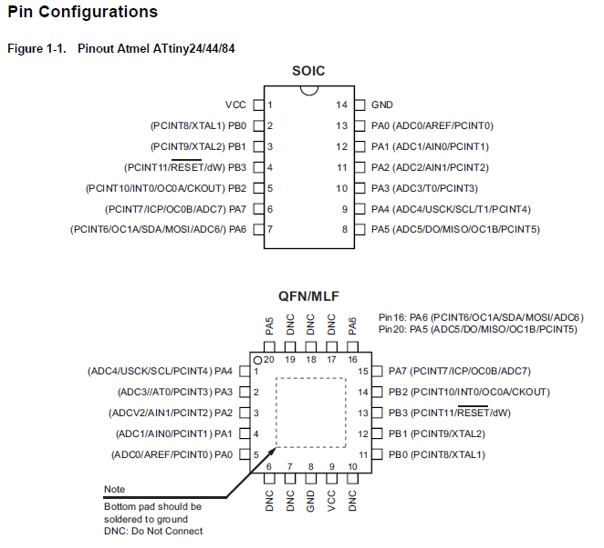
It can come in SOIC or QFN/MLF type packages.
Another important detail is the block diagram of the microcontroller
“The Atmel® AVR® core combines a rich instruction set with 32 general purpose working registers. All 32 registers are directly connected to the arithmetic logic unit (ALU), allowing two independent registers to be accessed in one single instruction executed in one clock cycle. The resulting architecture is more code efficient while achieving throughputs up to ten times faster than conventional CISC microcontrollers.”
We can also see that there is a single 8-bit data bus for both program memory (Flash ROM) and data memory (SRAM).
This is a typical RISC (Reduced instruction set computing) architecture that uses a reduced number of registers (32 in this case) to execute the 123 instructions it has.
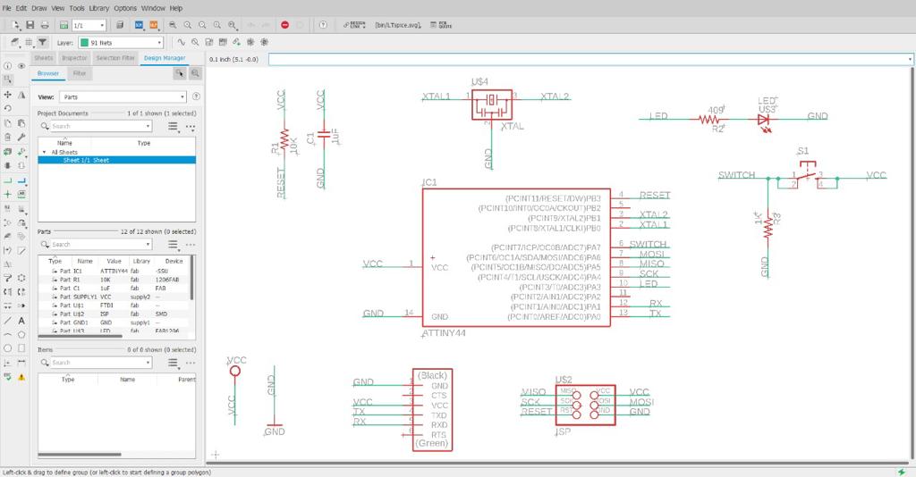
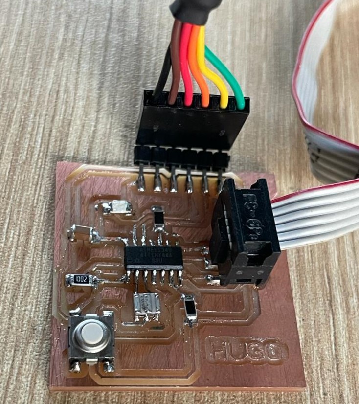
Going back to the PCB, I made a modification to the schematic to add an LED and a pushbutton.
Schematic
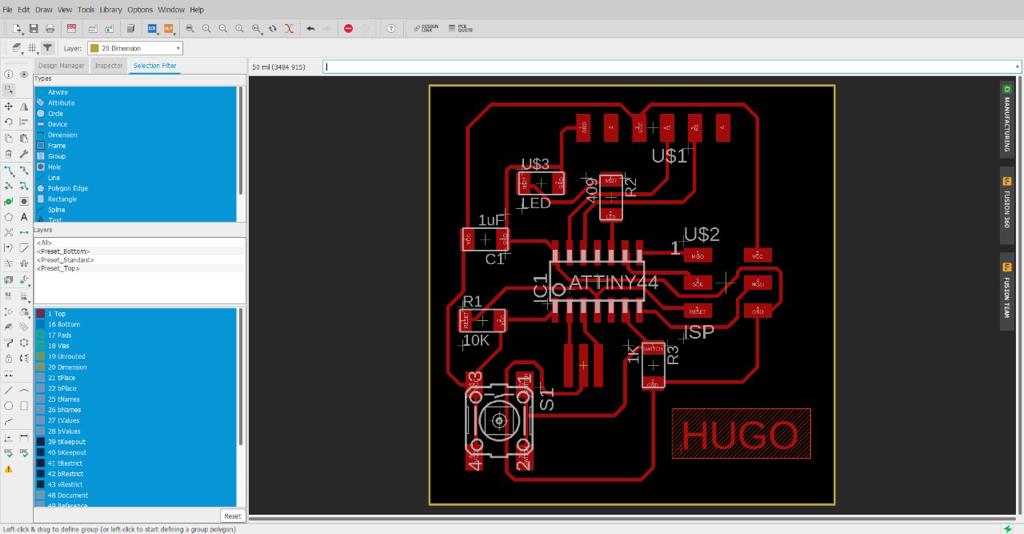
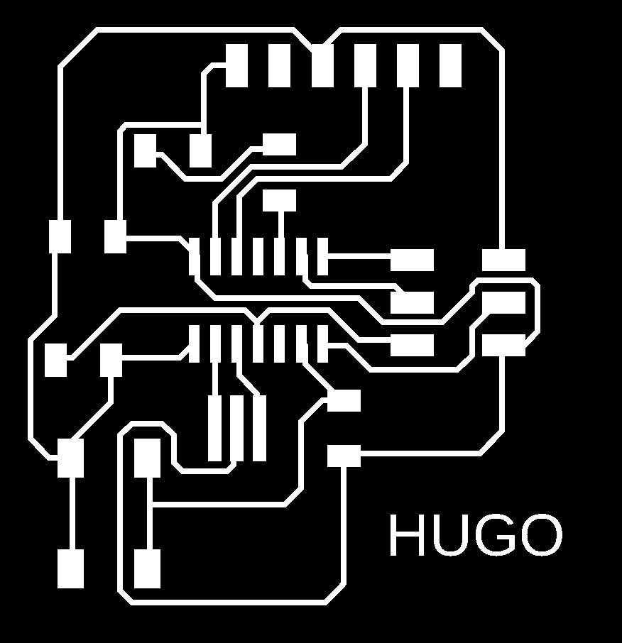
PCB
To program the ATtiny microcontroller PCBs using the Arduino IDE software, we must first install the board package containing the ATtinys.
The developer David Mellis created a board package for ATtiny that he shares from his website:highlowtech
We must follow the following procedure:
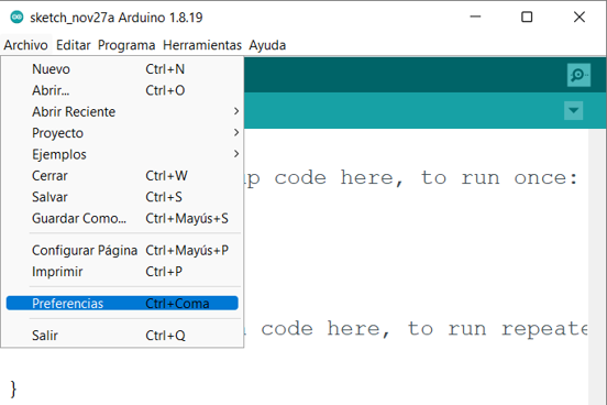
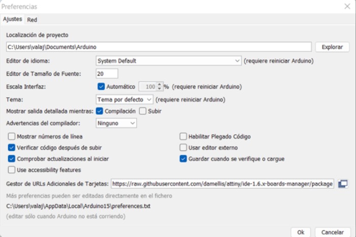
We load the Arduino IDE software and open the Preferences option from the Files menu.
From the Preferences window we paste the following path: https://raw.githubusercontent.com/damellis/attiny/ide-1.6.x-boards-manager/package_damellis_attiny_index.json
in the Additional Card URLs Manager box.
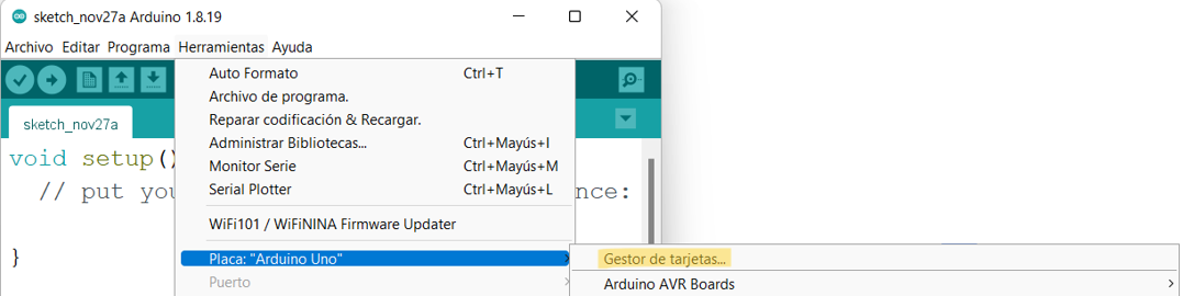
Open the Card Manager window from the Tools / Card menu.
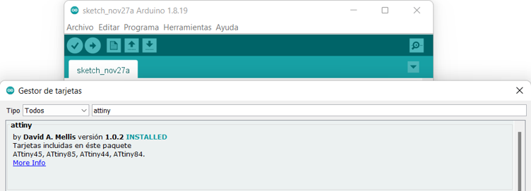
From the Card Manager, in the Search box type attiny and we will find the David Mellis card package. Proceed to install it.
Once the attiny board package is installed we can write the code for our PCB.
I opened a new sketch and wrote the following code:
define led 3
define button 7
void setup() { // put your setup code here, to run once: pinMode(led, OUTPUT); pinMode(button, INPUT); }
void loop() { // put your main code here, to run repeatedly: int value = digitalRead(button); if(value == HIGH){ digitalWrite(led, HIGH); } else{ digitalWrite(led, LOW); } }
From the Arduino IDE I select the ATtiny44 microcontrollers and set the additional parameters:
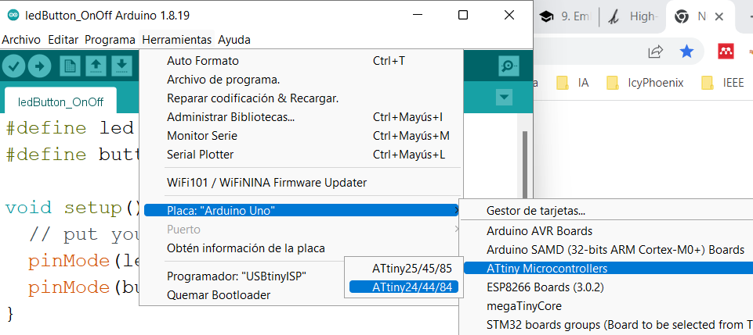
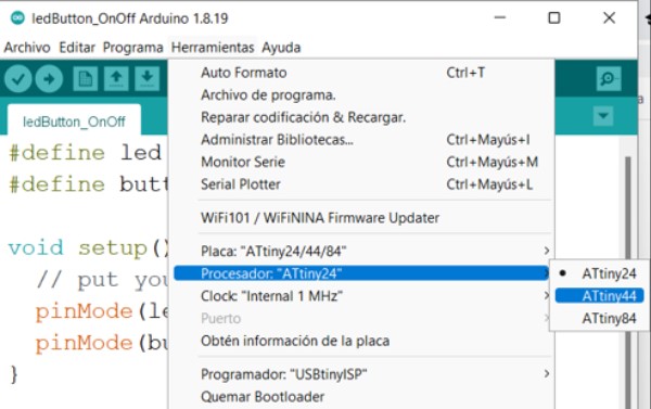
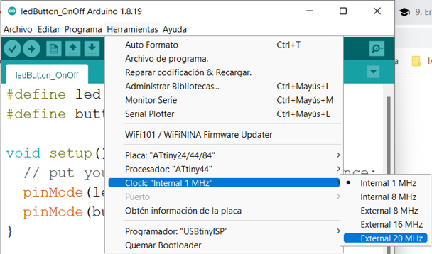
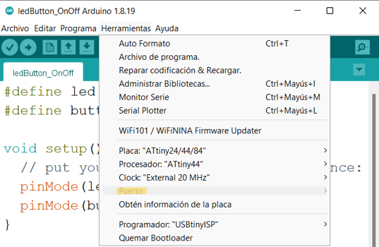
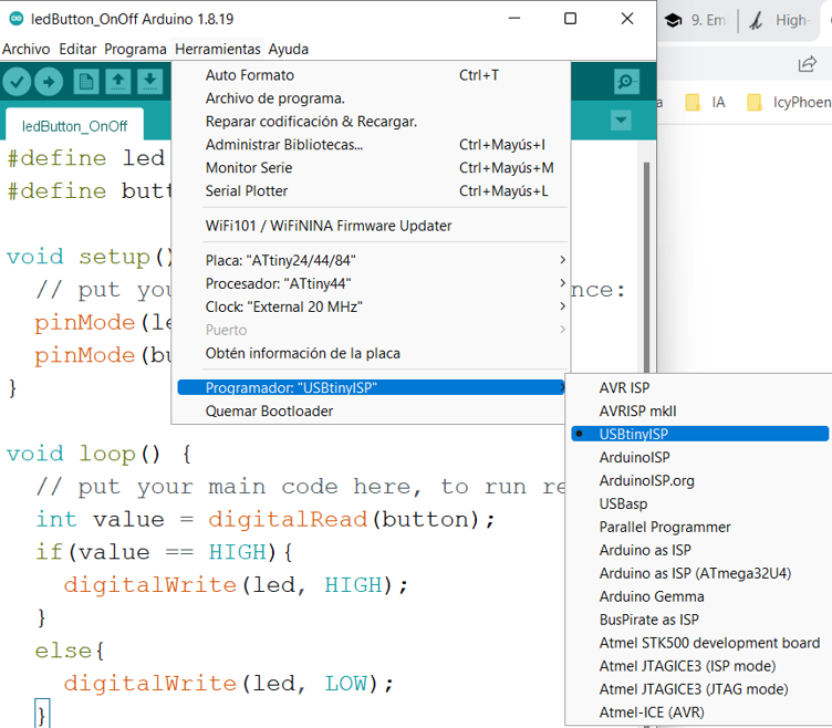
I connect my card and proceed to program.
In the following video we can see how it works:
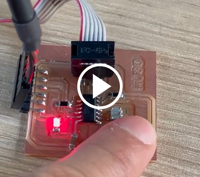