14. Networking and communications
This week I worked on networking and communications.
Group Assignment
For this group assignment we decided to communicate a micro SD memory reader (SPI protocol) with an LCD display (i2C protocol).
More information about SPI protocol https://www.circuitbasics.com/basics-of-the-spi-communication-protocol
More information about the i2C protocol. https://www.circuitbasics.com/basics-of-the-i2c-communication-protocol/
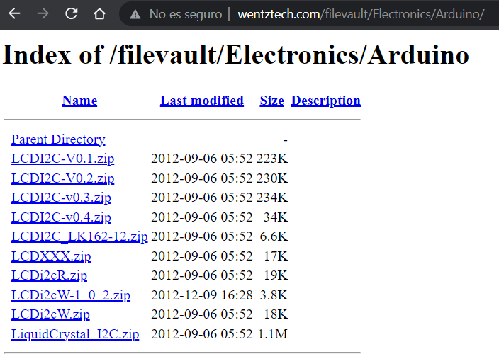
Download and install the Arduino library for i2C LCDs. http://www.wentztech.com/filevault/Electronics/Arduino/
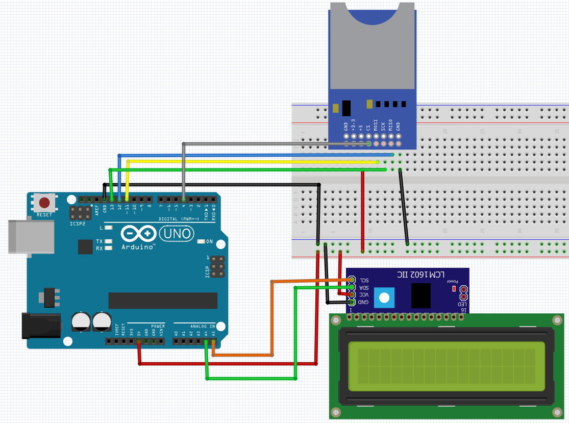
Assemble the following circuit:
The circuit works as follows: The Arduino will read the information stored in the micro SD memory, accessing through the i2c protocol. The Arduino will send the information collected from the micro SD memory and publish it on the LCD screen, accessing the latter through the SPI protocol.
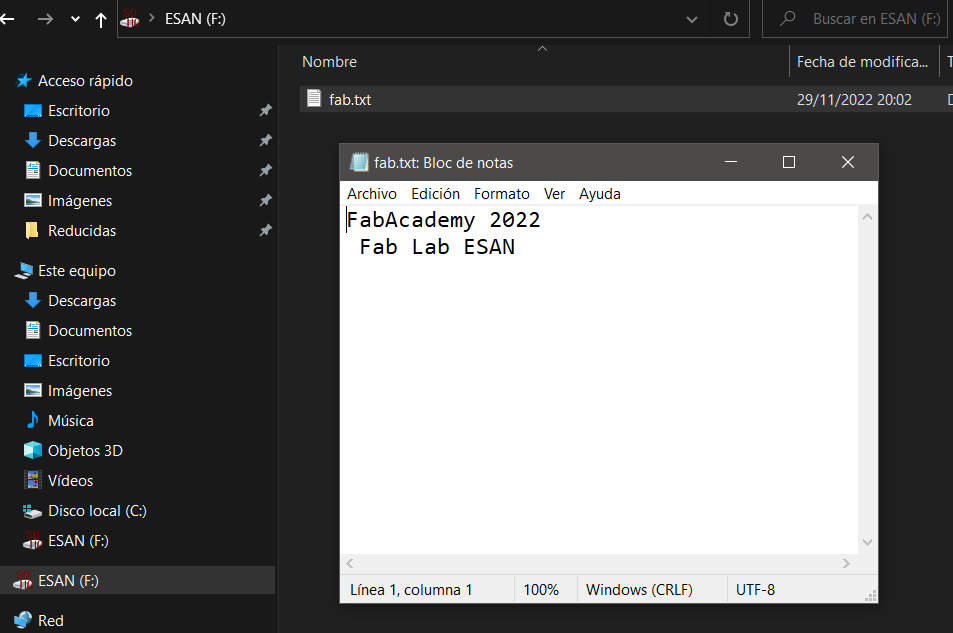
We open the Notepad and create a text file with the following message: “FabAcademy 2022”.
We write the following code in Arduino:
include 
include 
include 
define COLUMS 20
define ROWS 4
define LCD_SPACE_SYMBOL 0x20 //space symbol from the LCD ROM, see p.9 of GDM2004D datasheet
LiquidCrystal_I2C lcd(PCF8574_ADDR_A21_A11_A01, 4, 5, 6, 16, 11, 12, 13, 14, POSITIVE);
File myFile;
void setup() { Serial.begin(9600);
while (lcd.begin(COLUMS, ROWS) != 1) //colums - 20, rows - 4
{
Serial.println(F(“PCF8574 is not connected or lcd pins declaration is wrong. Only pins numbers: 4,5,6,16,11,12,13,14 are legal.”)));
delay(5000);
}
lcd.print(F(“PCF8574 is OK…”)); //(F()) saves string to flash & keeps dynamic memory free delay(2000);
lcd.clear();
//set 1-st colum & 2-nd row, 1-st colum & row started at zero lcd.setCursor(0, 1);
Serial.println(“Starting SD …”); if (!SD.begin(4)) { Serial.println(“It couldn’t start”); return; } Serial.println(“SD is OK”);
myFile = SD.open(“fab.txt”);//Open the file if (myFile) { Serial.println(“fab.txt:”); lcd.clear(); while (myFile.available()) { char data = myFile.read(); lcd.print(data); } myFile.close(); //Close the file. } else { Serial.println(“Error trying to open the file.”); } }
void loop() {
}
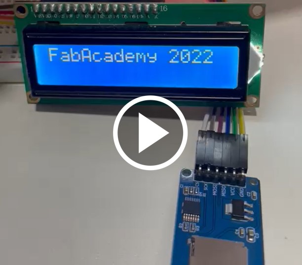
We download it to the Arduino UNO and test the operation.
Individual Assignment
For this week I decided to try RS232 serial asynchronous communication. The complete information on how this protocol works can be found at Codrey.
Therefore, I decided to make the bipolar stepper motor controller board found at The Fab Academy 2022 Schedule.
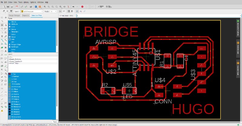
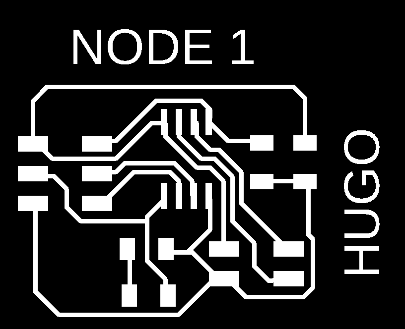
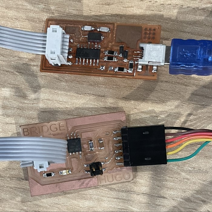
Guided by the example I designed my own boards using Eagle, two boards for the nodes and one for the bridge.
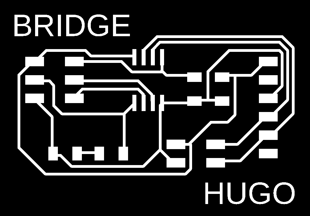
BRIDGE
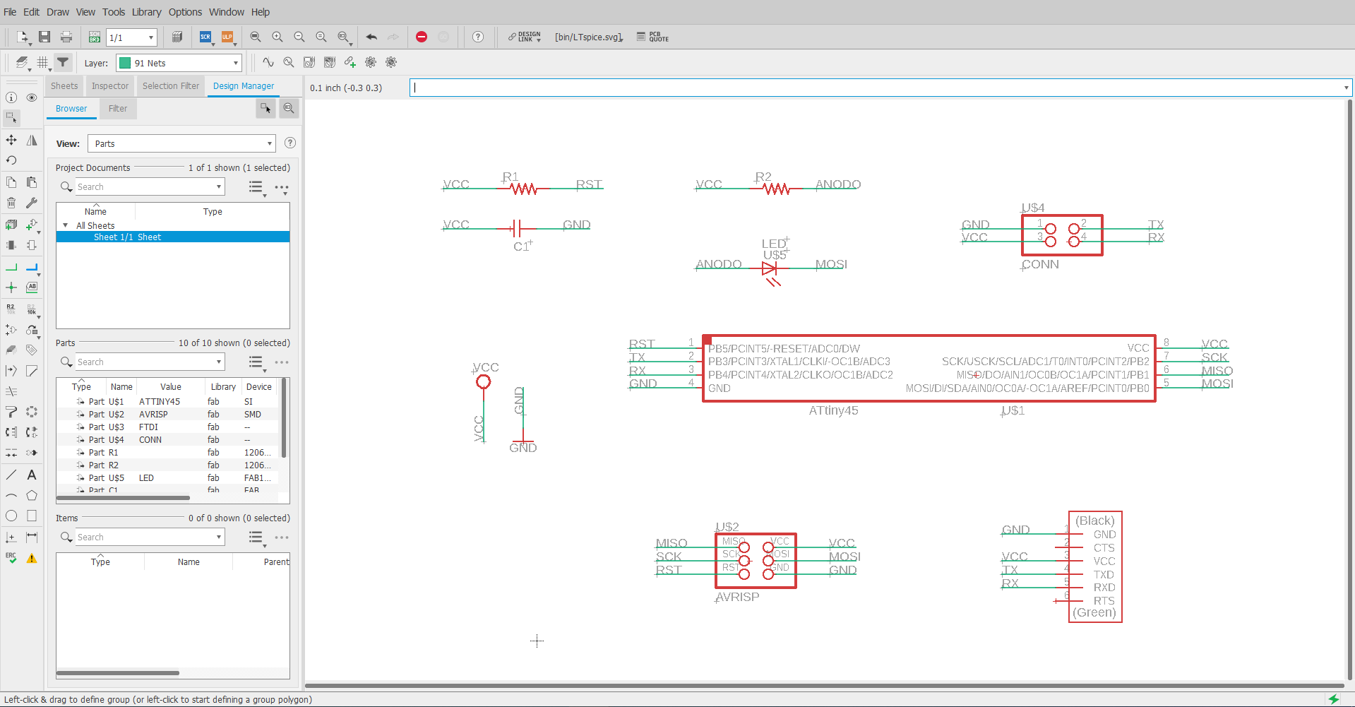
The list of components used were: - (01) Attiny45 - (01) Capacitor 1uF - (04) 10K resistor - (01) LED - (01) Resistor 1K - (01) FTDI 6x1 Connector - (01) ISP connector 3x2
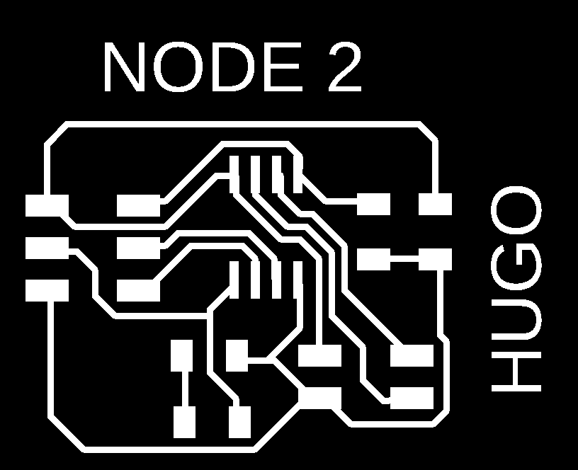
NODE
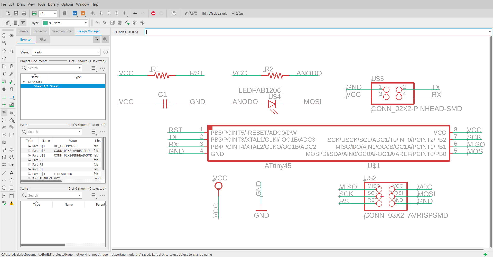
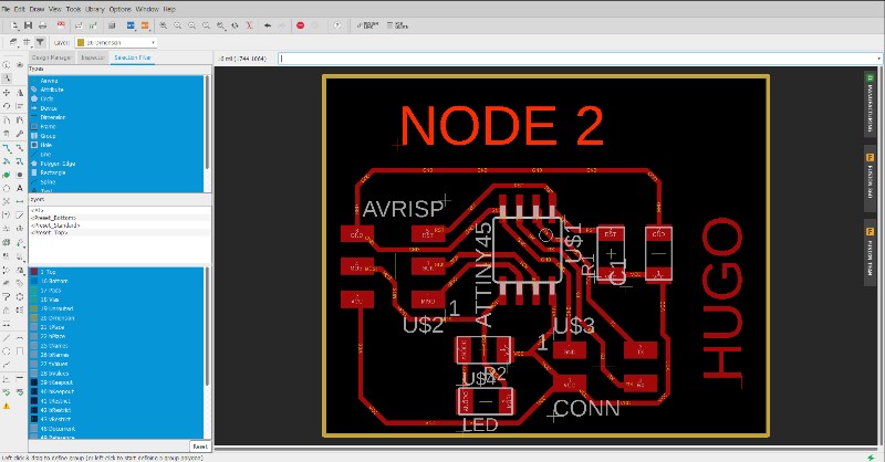
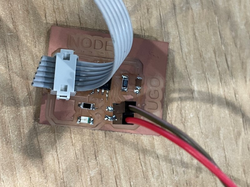
The list of components used were: - (01) Attiny45 - (01) Capacitor 1uF - (04) 10K resistor - (01) LED - (01) Resistor 1K - (01) Connector 2x2 - (01) ISP 3x2 Connector
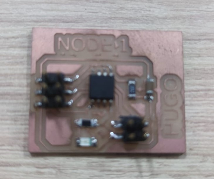
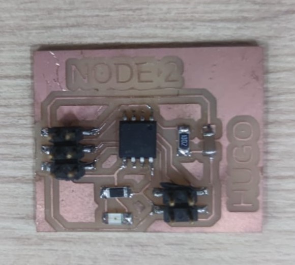
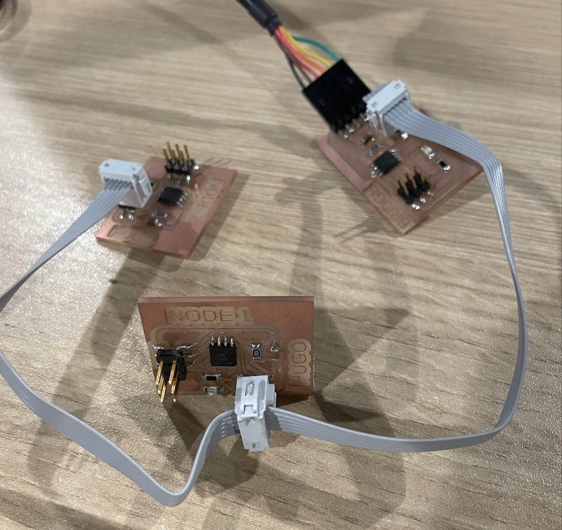
I made two Node type boards and to differentiate them each board indicates Node 1 and Node 2.

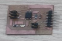
After fabricating the boards and soldering the components they look like this:
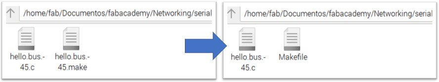
Then we proceeded to download the files and rename the hello.bus.45.make file to Makefile.
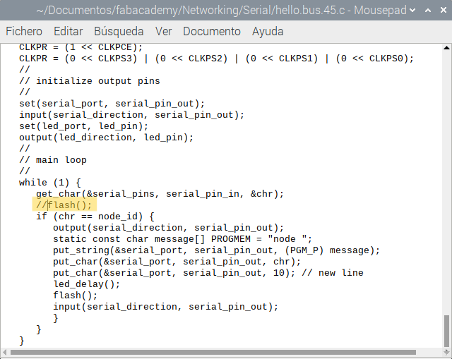
Before programming we have to edit the hello.bus.45.c file. I proceed to comment the line with the flash() function that is before the if() structure. With this modification the LEDs of each card will light only when it corresponds to them, that is to say, if I send a message to node 1, only the LED of node 1 should light.
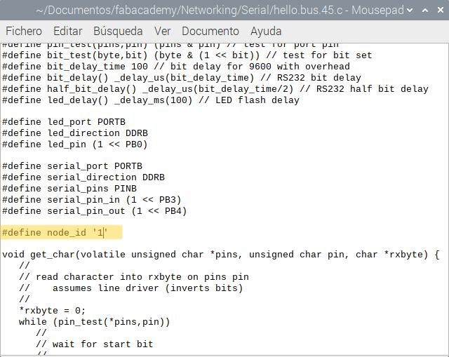
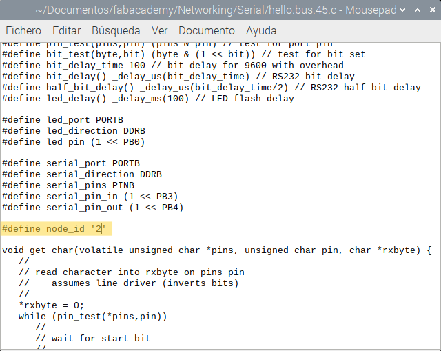
We must also modify the identifier (ID) for each card as appropriate:
Bridge → node_id ‘0’ Node 1 → node_id ‘1 Node 2 → node_id ‘2’
By default, it is with the value 0 corresponding to Bridge. Therefore, when we want to program the nodes we will have to modify the ID accordingly.
Connect the USBTiny programmer and the FTDI cable to the Bridge board.
Then we verify the connections from the terminal with the command “lsusb”.
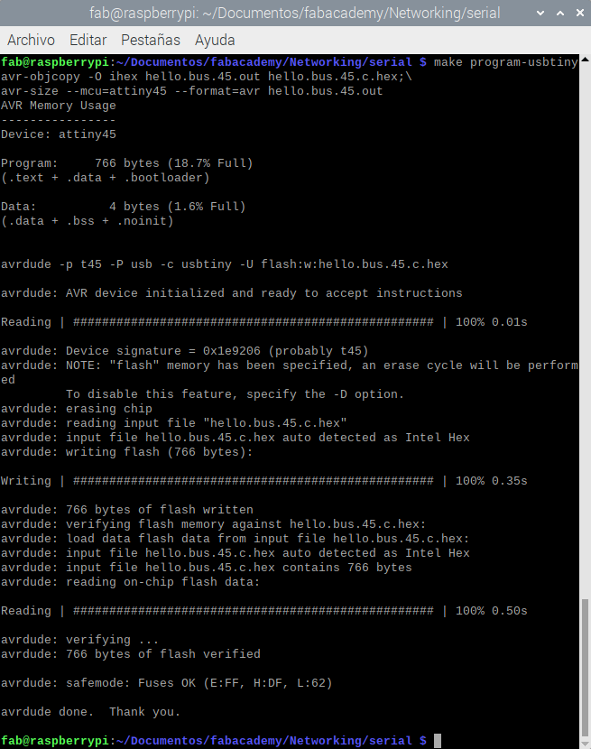
Finally, from the linux terminal we access the folder with the .c and Makefile files and execute the following command: “make program-usbtiny”.
Repeat the process for the nodes by editing the file as previously indicated.
After programming the boards we make the connection between them as shown in the image, it must be considered that in each connector must match point to point communication lines (RX, TX) and power (VCC, GND).
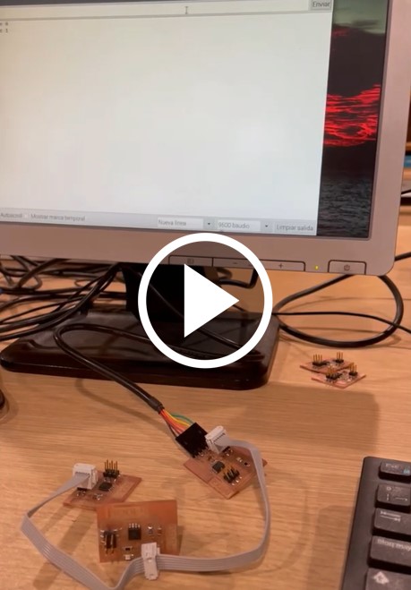
To perform the tests we need to run the term.py file. From the linux terminal we execute the following command: “python term.py /dev/ttyUSB0 9600”.
A window will open and we will press the numeric keys: 0 → To send a message to the Bridge and turn on its LED. 1 → To send a message to Node 1 and turn its LED on 2 → To send a message to Node 2 and turn its LED on
Files
- .c file
- .py file
- make file
- Schematic BRIDGE eagle file
- Board BRIDGE Eagle file
- Schematic NODE eagle file
- Board NODE Eagle file
- PNG interior BRIDGE image
- PNG traces BRIDGE image
- PNG interior NODE image
- PNG traces NODE1 image
- PNG traces NODE2 image