9. Embedded programming
GROUP ASSIGNMENT
- Compare the performance and development workflows for other architectures
From the following link you can access the Group Assignment: Group Assignment
INDIVIDUAL ASSIGNMENT:
-
Browse through the data sheet for your microcontroller
-
Use your programmer to program your board to do something
-
Extra credit: try other programming languages and development environments
For this assignment they ask us to modify some of the plates that we can find in the following link embedded_programming index

Since we only have ATtiny microcontrollers, I decided to modify the board that uses the ATtiny 44 microcontroller.
I downloaded their data sheet, to review and analyze it, from the following link: https://ww1.microchip.com/downloads/en/DeviceDoc/Atmel-7701_Automotive-Microcontrollers-ATtiny24-44-84_Datasheet.pdf
Its main characteristics:

The ATtiny44 can be obtained in 2 packaging presentations: SOIC type and QFN/MLF type

It is also important to analyze the block diagram of the microcontroller
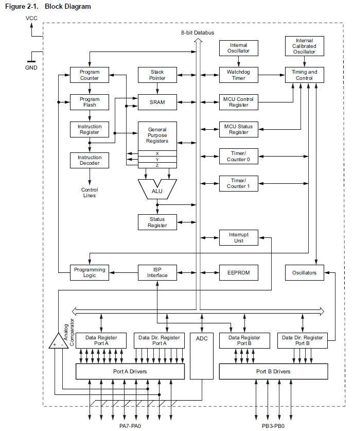
The ATtiny 44 has a RISC (Reduced instruction set computing) architecture that uses only 32 registers to execute all its instructions.
Program memory (Flash ROM) and data memory (SRAM) share the same 8-bit data bus.
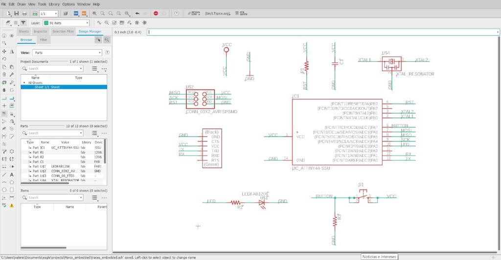
The schematic diagram of my board:
PCBs

I install David Mellis’s card package for ATtiny microcontrollers https://highlowtech.org/?p=1695
We must follow the following procedure:
From the Arduino IDE software we open the Preferences window found in the Files menu. Paste the following route in the Additional Card URLs Manager box: https://raw.githubusercontent.com/damellis/attiny/ide-1.6.x-boards-manager/package_damellis_attiny_index.json
In the Search box of the Card Additional URLs Manager, we look for and install the David Mellis card package.

The code I used to test my card is as follows:
int led = 3; int pushButton = 7;
void setup() { // put your setup code here, to run once: pinMode(led, OUTPUT); pinMode(pushButton, INPUT); }
void loop() { // put your main code here, to run repeatedly: int statusButton = digitalRead(pushButton); if(statusButton == HIGH){ digitalWrite(led, HIGH); } else{ digitalWrite(led, LOW); } }
From the Arduino IDE I configured my ATtiny 44 based board as follows:
Plate: ATtiny24/44/84 Processor: ATtiny44 Clock: External 20 MHz Port: COM Developer: USBtinyISP
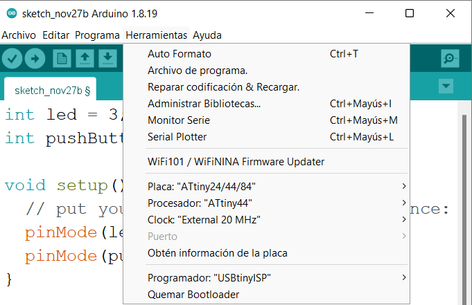
I can now program my PCB.

In the following video we can see how it works:
