Embedded Programming
Week 7
Review
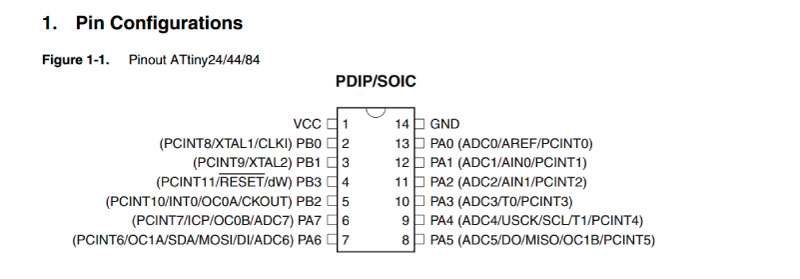
For this week’s assignment we have to program the board designed in Week 6 (electronics design) to do something. The assignment includes reading the Attiny44 Microcontroller Datasheet, but I think this must be done in week 6 in order to design the board properly. If you check my week of Electronics Design, you will see that I had to redesign my board because I used pins in the Attiny44 that can't be used to program the Leds (in this case). There are pins with specific functions for communication and data transmission.Check the datasheet BEFORE design your board.
Be able to program this board took me a few weeks of hard work since I had no knowledge in programming. I will try to explain how it worked for me and how I solved some troubles.
Programming the Board with the Arduino IDE
I found a very useful tutorial of embedded programming from Fab Lab UNI. All the process is very well detailed and basically all the steps that I followed.
1. Installig the Arduino IDE
The first thing we need to do is download the necessary software. Get the Arduino IDE from the official Arduino webpage. I downloaded the Arduino 1.0.6 (the classic Arduino IDE) for windows, but the newest version works well too.
2. Add the Attiny Libraries
With this tutorial from High Low tech (research group of MIT Media Lab) we are able to program the tiny’s with the Arduino IDE. We need to download the .zip for our current IDE version. In my case I downloaded the “ide-1.0.x.zip”. To install the libraries locate your Arduino Sketchbook folder (you can find its location going to file>preferences in the Arduino IDE. Normally it’s in Documents/Arduino). Second create (if is not) a sub folder called “hardware” and paste on it the unzipped folder (attiny).
3. Install all the necessary drivers
It’s necessary to install all the next drivers in order to be able to program our board.
- FabISP driver (USBtiny).Download
- FTDI driver. Download
- Winavr for the Avrdude. Download
- (If your you are using the avrisp mkii). Download
Blink + Button Code.
We are ready to program our Attiny44 it’s time to make the Code. One of the things to take in account is that the Attiny44 pin numbers have a corresponding number in Arduino to be programed. For example, in my Schematic I have the button in the pin 6; the corresponding pin number in the Arduino IDE is 7.
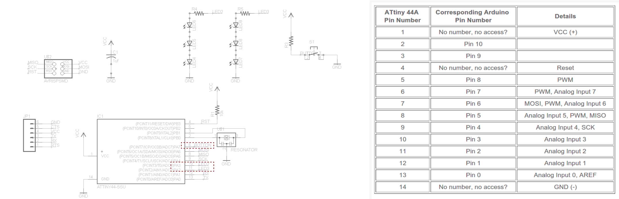
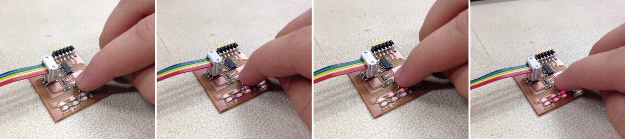
I have (3) red leds in series in the pin 10 and (3) red leds in series in the pin 11. My program (based on Aristarco Cortes Code and this youtube tutorial) consist to push the button to turn on the leds. The first push turn on the first series of leds in a blink, the second push turn on the second series of leds in a blink, the third push turn on the two series of leds and the fourth turn of the leds and restart the program.
/*Blink + Button // Juan Pablo Gutierrez Salazar
Based on Aristarco Cortes Code and this youtube tutorial
> https://www.youtube.com/watch?v=eWRLXxrKpt8 */

// Definir los pines de los leds.
// Darles un nombre.
// Definir Contador para el boton.

int led = 3;
int led2 = 2;
int contador = 0;

// the setup routine runs once when you press reset:
void setup() {
  // Leds as outputs.
  // Boton as input.
  pinMode(led, OUTPUT);
  pinMode(led2, OUTPUT);
  pinMode(7, INPUT);
}

// the loop routine runs over and over again forever:
void loop() {
  if (digitalRead(7)==LOW)
 { delay(20);
  contador++;
  if(contador>=5) //Cuando el contador es mayor de 5 vuelve a 0
  {contador=0;}

 }
  if(contador==0) // 0 pulsos ninguna respuesta
 { digitalWrite(led, LOW);
 }
  if(contador==1)
 { digitalWrite(led, HIGH);   // 1 pulso prende la primera tira de leds
  delay(20);               // wait
  digitalWrite(led, LOW);    // 1 pulso apaga la primera tira de leds
  delay(20);               // wait
 }
else if (contador==2)
{digitalWrite(led2, HIGH);   // 2 pulsos prende la segunda tira de leds
  delay(20);               // wait
  digitalWrite(led2, LOW);    // 2 pulsos apaga la segunda tira de leds
  delay(20);

}
else if (contador==3)
{digitalWrite(led, HIGH);   // 3 pulsos prende la segunda tira de leds
{digitalWrite(led2, HIGH); // 3 pulsos prende la segunda tira de leds

}
 }
else if (contador==4)
{digitalWrite(led, LOW);   // 4 pulsos apaga la primera tira de leds

  digitalWrite(led2, LOW);  // 4 pulsos apaga la segunda tira de leds

}
}
The Next step is uploading our code to our Attiny44 microcontroller. Follow the next steps.
- 1. We need to select the board. Go to Tools > Board > Attiny44 (external 20MHz clock).
- 2. Set the serial Port. Tools > Serial Port > COM (?) (You can check the port where the Arduino is connected in the device manager on Windows).
- 3. Set the Programmer in Tools>Programmer>USBtinyISP.
- 4. Verify the Code.
- 5. Upload the Code.
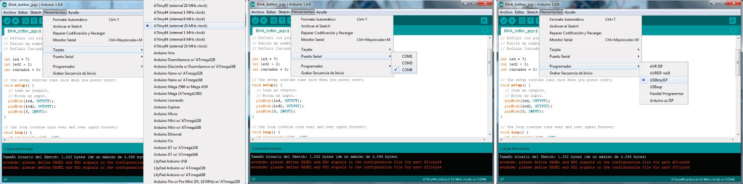
The next warning is not a mistake; the program should be successfully loaded in our board.
Tamaño binario del Sketch: 1.202 bytes (de un máximo de 4.096 bytes) avrdude: please define PAGEL and BS2 signals in the configuration file for part ATtiny44 avrdude: please define PAGEL and BS2 signals in the configuration file for part ATtiny44Final Result
Final Result
The program is running correctly. You can see the video bellow.
This week was really cool, seeing the board works was really exciting. From this week I learned to find the solution when something don’t work and a few things of programming.