Input Devices
Week 10
Review
For this week`s assignment I wanted to make the first approximation to servomotors and the possible electronic system of my final project. Get to understand how a photoresitor and a potentiometer (inputs) can control a servomotor (output). The main goal is to move the servomotor whit the photoresistor and the potentiometer.
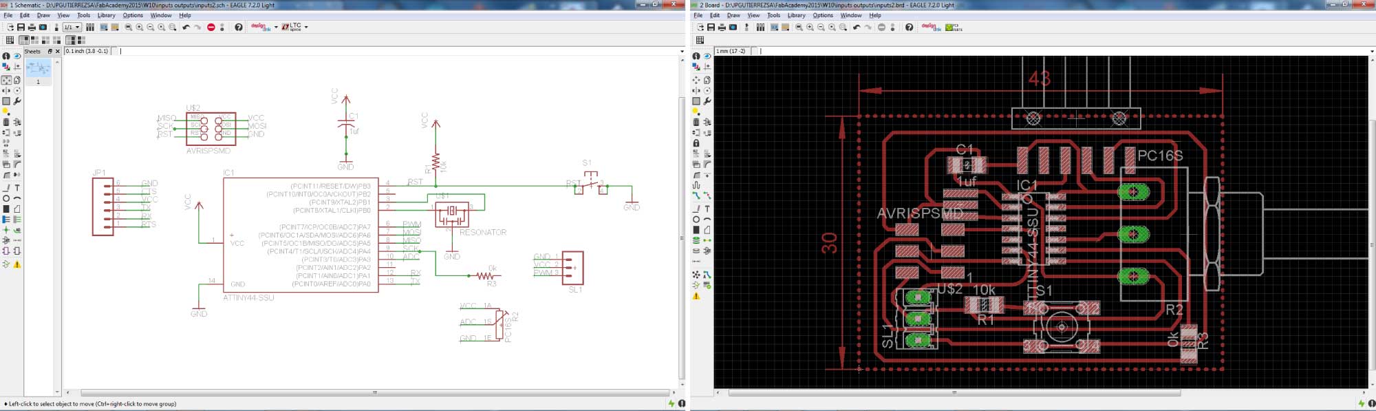
Photoresistor + Servo Board Design
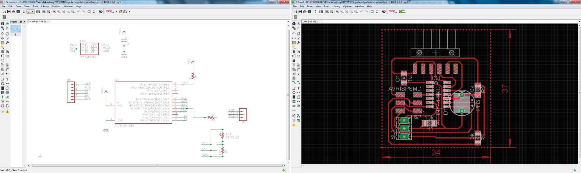
I wanted to combine inputs & outputs in the same board design. With help from some electronic engineering students, I based my design in the HELLO ECHO BOARD from Week 6. I added a few new components detailed next.
- 6-double pin programming header
- Microcontroller: attiny44A
- FTDI header
- 3-pin servo header
- 2 Resistor (value 10k)
- Capacitor (valeu 1uf)
- Photoresistor
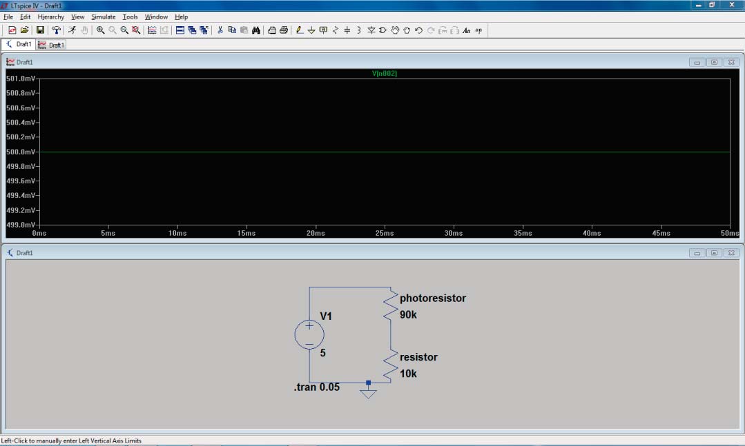
LTspice is a great software for simulate the circuits. I used it to define the value of the resistor connected to the input. The result was a 1K resistor.
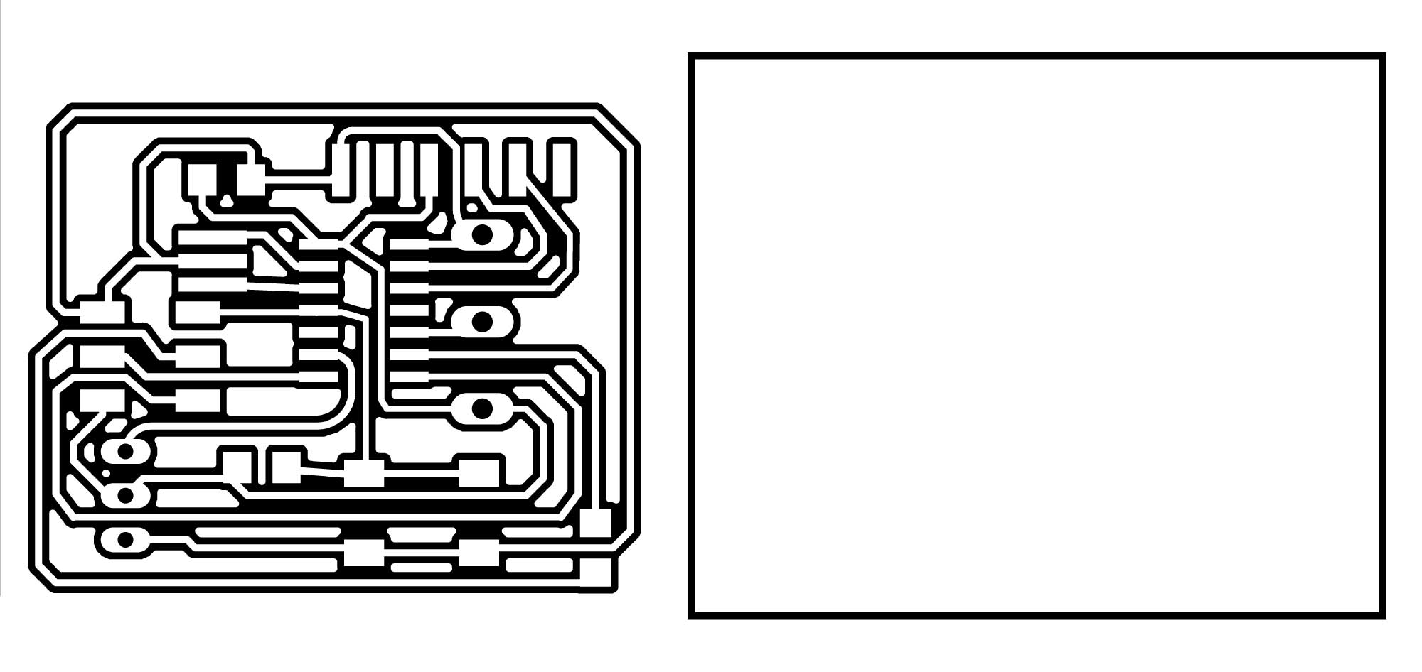
Milling Process
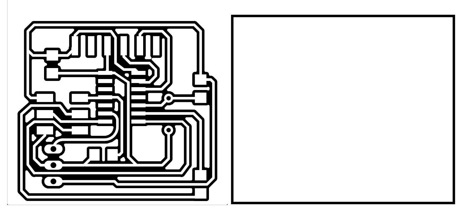
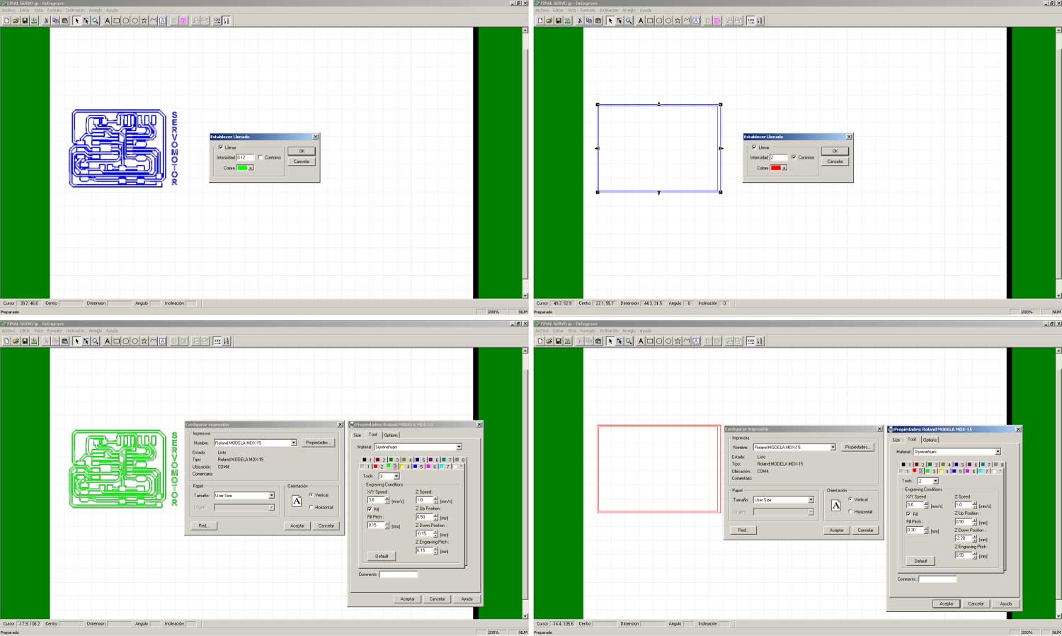
Once our eagle board is ready turn off all the layers except the top layer. Go to File > Export > Image. Check the Monochrome box and set the resolution to 2400 dpi. Click on Save as .BMP (Windows Bitmap File). Remember that our Modela Software (Dr. Engrave) only accepts .bmp and .dxf files.
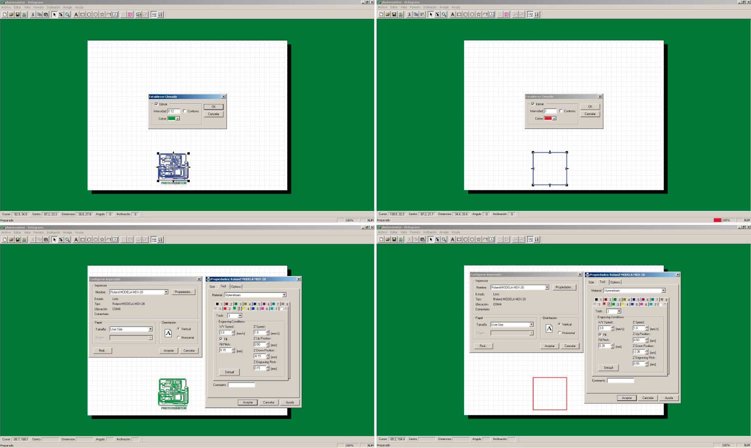
We are going to work this week with the Roland Modela MDX-20 Machine. To make the traces of our board we're going to use the 1"/64" end mill, with the next parameters:
- >Fill Intensity: 0.12 - Green
- >X/Y Speed: 3.0 mm/S
- >Z Speed: 1 mm/s
- >Fill Pitch: 0.15 mm
- >Z Up Position: .50 mm
- >Z Down Position: 0.15 mm
- >Z Engraving Pitch: 0.15 mm
Cut the board with the 1”/32” end mill with these parameters.
- >Fill Intensity: 2 - Red
- >X/Y Speed: 3.0 mm/S
- >Z Speed: 1 mm/s
- >Fill Pitch: 0.30 mm
- >Z Up Position: .50 mm
- >Z Down Position: 2.20 mm
- >Z Engraving Pitch: 0.55 mm
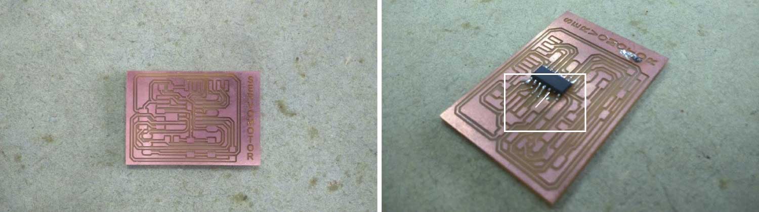
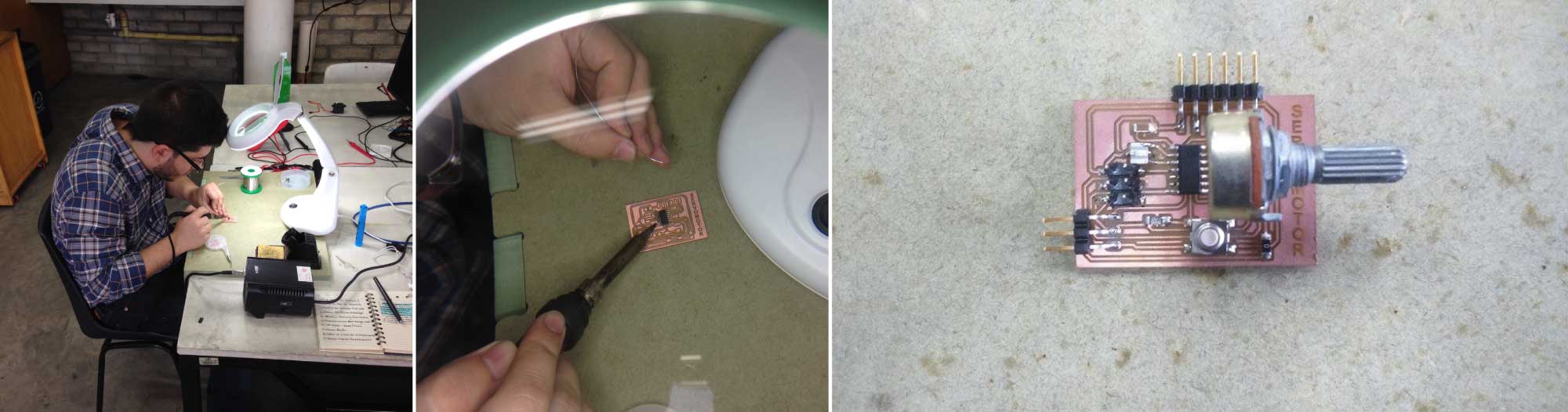
Soldering
I felt more confident soldering this board but always it could be better. The attiny44 is the most difficult component to solder on the board.

Programing
I had some troubles trying to program this board but finally I made it. The attiny44 don’t support some functions that I wrote in my code, but surfing the web I found this tutorial in wich i based to program this kind of microcontroller
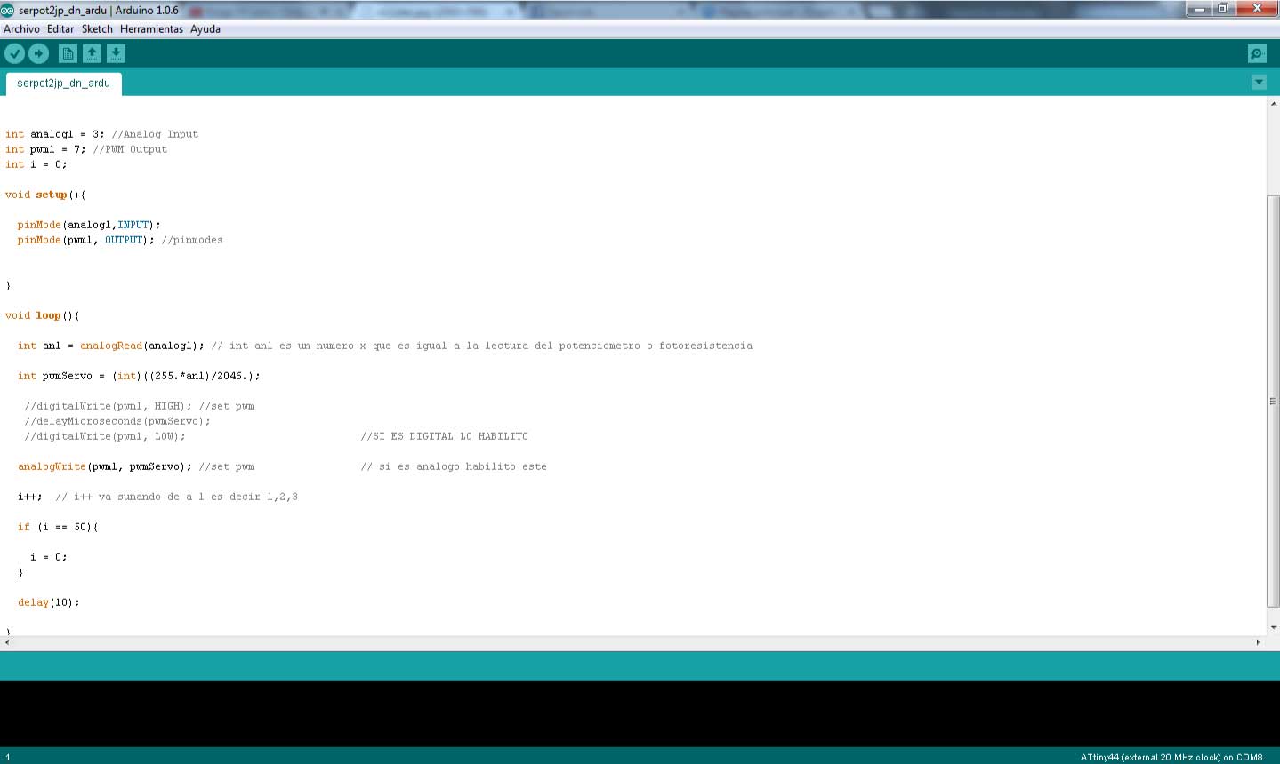
Servo + Photoresistor_Code
/*
Juan Pablo Gutierrez Salazar Attiny code for servo controlling with help from Daniel Pineda.
based on https://github.com/Jan--Henrik/Attiny-PWM-generator/blob/master/Final%20code
*/
int analog1 = 3; //Analog Input
int pwm1 = 7; //PWM Output
int i = 0;

void setup(){

  pinMode(analog1,INPUT);
  pinMode(pwm1, OUTPUT); //pinmodes
}

void loop(){

  int an1 = analogRead(analog1); // lecture number photoresistor
  int pwmServo = (int)((255.*an1)/2046.);
  analogWrite(pwm1, pwmServo); //set pwm

  i++;
  if (i == 50){
    i = 0;
  }

  delay(10);

}
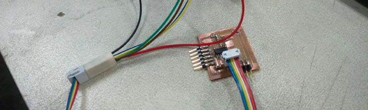
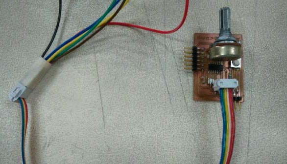
The Result
Potentiometer + Servo Board Design
This board is almost the same as the first one only by replacing the photoresistor for a potentiometer. It also has a button to restart the program. The components detailed next.
- 6-double pin programming header
- Microcontroller: attiny44A
- FTDI header
- 3-pin servo header
- 1 Resistor (value 10k)
- 1 Resistor (value 0k_jumper)
- Capacitor (valeu 1uf)
- Potentiometer
- Button
Milling Process
Export the image following the preview steps above.
Use the same parameters to mill and cut the board.
Soldering
Soldering the attiny44 I made a mistake and solder two pins together, but the problems didn’t ended there. When I tried to unsolder them, I damaged 1 pin of the microcontroller and a couple of the board traces. I had to cut a new one and start soldering again.
The board ready to be programed.
Programing
To program this board I also used the tutorial code with some modifications. This code didn't worked as I expect but I’m working on it to make it better.
Servo + Potentiometer_Code
/*
Juan Pablo Gutierrez Salazar Attiny code for servo controlling with help from Daniel Pineda.
based on https://github.com/Jan--Henrik/Attiny-PWM-generator/blob/master/Final%20code
 */

int rx = 0;
int tx = 1;
int analog1 = 3; //Analog Input
int pwm1 = 7; //PWM Output

#include <"SoftwareSerial.h">
SoftwareSerial mySerial(0, 1); // RX, TX

void setup(){
  pinMode(analog1,INPUT);
  pinMode(pwm1, OUTPUT); //pinmodes
  mySerial.begin(9600);
}

void loop(){

   mySerial.println(pwm1);
  int an1 = analogRead(analog1);

  if (an1 >= 900 && an1 <= 1024) {

    digitalWrite(pwm1, HIGH); //set pwm
    delayMicroseconds(100);
    digitalWrite(pwm1, LOW);
  }

  if (an1 >= 700 && an1 <= 899 ) {

    digitalWrite(pwm1, HIGH); //set pwm
    delayMicroseconds(120);
    digitalWrite(pwm1, LOW);
  }

  if (an1 >= 501 && an1 <= 699 ) {

    digitalWrite(pwm1, HIGH); //set pwm
    delayMicroseconds(140);
    digitalWrite(pwm1, LOW);
  }

  else if (an1 <= 500 && an1 >= 301) {

    digitalWrite(pwm1, HIGH); //set pwm
    delayMicroseconds(160);
    digitalWrite(pwm1, LOW);

  }

    else if (an1 <= 300 && an1 >= 101) {

    digitalWrite(pwm1, HIGH); //set pwm
    delayMicroseconds(180);
    digitalWrite(pwm1, LOW);

  }

    else if (an1 <= 100 && an1 >= 0) {

    digitalWrite(pwm1, HIGH); //set pwm
    delayMicroseconds(200);
    digitalWrite(pwm1, LOW);

  }
  delay(18);


}
The Result
This was a great week; I could program two different boards that could be useful for my final project. The photoresistor board works pretty well. I will continue working to improve the codes to make the servo response more stable.