Computer-Controlled Machining
Week 8
Make Something BIG!
Review
This week assignment consist to make something big, like a furniture that has to assembly without glue, nails or screws in the ShopBot CNC Milling Machine, taking in count the material thickness for press fit joints. In our Fab we have a Full Size PRSalpha ShopBot CNC, the 1.22m x 2.44m reference. Get more info of the machine here.
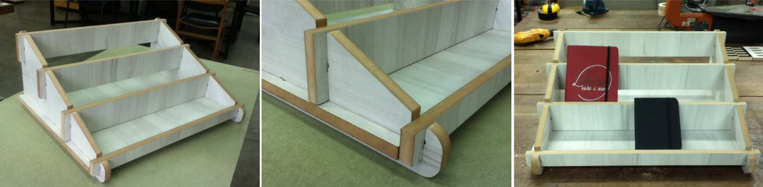
Notebook Stand
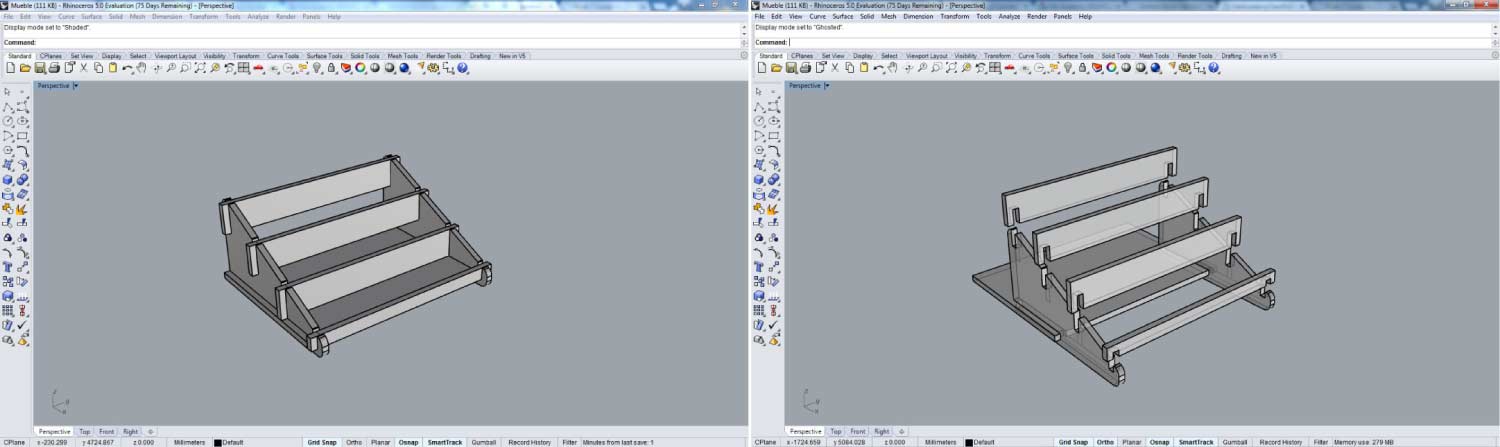
I wanted to make a notebook stand with wood leftovers that we had available on our lab of previous lab projects. This was a good way to recycle wooden pieces, so we are more efficient with our environment and our lab resources. I used Rhinoceros to design the notebook stand, and it’s basically composed of 2 side pieces, 4 front pieces and 1 base piece.
Fabrication Process
Once you have your 3d design, the next step is to convert the surfaces into curves for the machining process. I always draw a 1220mm x 2440mm (the comercial sheet) rectangle and nest all the pieces taking in count minimum 20mm of distance to one piece to another for a correct fixing. Export it like default dxf.
PartWorks is very easy and intuitive software for machining. It simplifies the steps in the cut process and the g-code generation. Once you have your 2d dxf file, open the PartWorks 3.5 and click on open an existing file. Select your dxf file and click open.
- >Set the size of the workspace (1220mm x 2440mm).
- >Set the material thickness.
- >Click on “use XY origin offset”
- >Set units to MM.
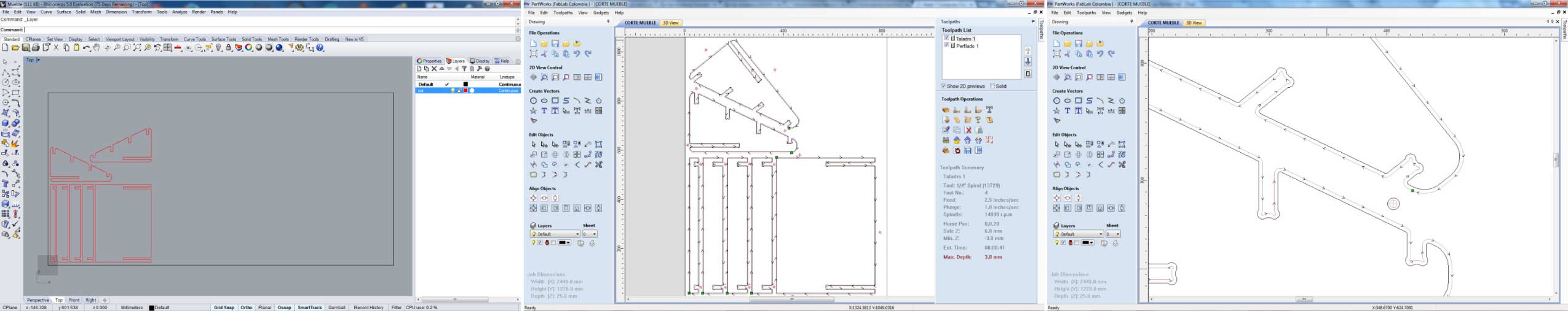
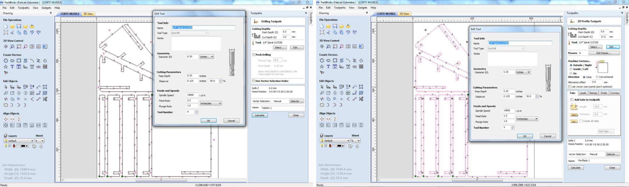
We need to set 2 toolpaths in order to cut our element. The First is a Drilling Toolpath. In create vectors options, we draw 10mm diameter circles for correct fixing of all the pieces. The screws head had 8mm diameter. So, with the 10mm Circles in the Drilling Toolpath we avoid injuries in our bit. Next we set the cut depth, in my case 3mm for the screws. The tool we use was a ¼ bit. The parameters were:
- Spindle Speed _ 14000 rpm
- Feed Rate_ 2.5 inches/sec
- Plunge Rate_ 1.0 inches/sec
The second one was the Profile Toolpath to cut the pieces. Set the cut depth depending on the material thickness in my case was 17.5 mm. The tool was the same, a ¼ bit and the parameters were.
- Spindle Speed _ 14000 rpm
- Feed Rate_ 2.5 inches/sec
- Plunge Rate_ 1.0 inches/sec
Previews Settings in the Shopbot Machine
- 1. Turn ON the machine in the control box.
- 2. Previously set with presses before the screws.
- 3. Screw each corner of the work space.
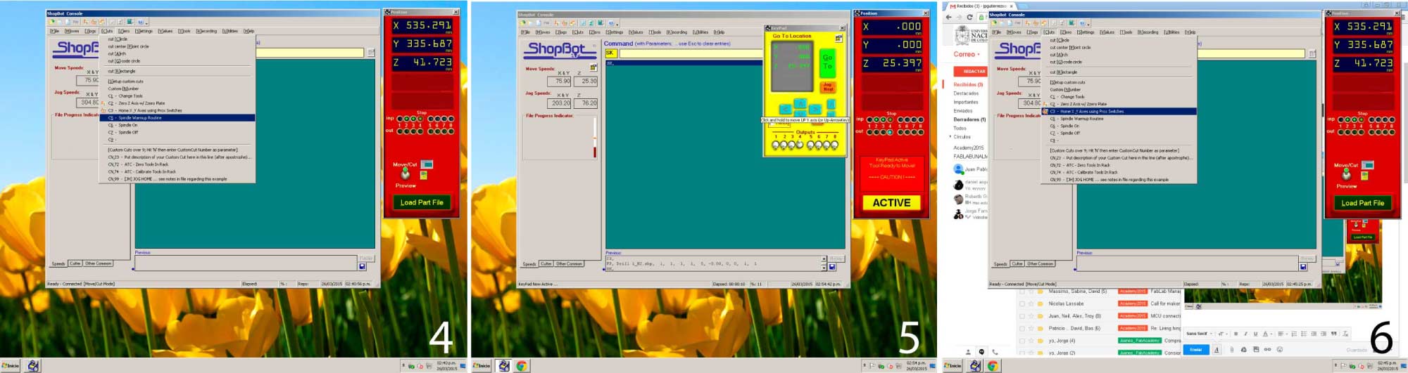
- 4. Open the Shopbot software, then go to Cuts>C5_Spindle Warmup Routine. This process will take 8 minutes aprox.
- 5. Press (K) to open the Key Pad. This would let you move the Spindle in the X,Y and Z axis.
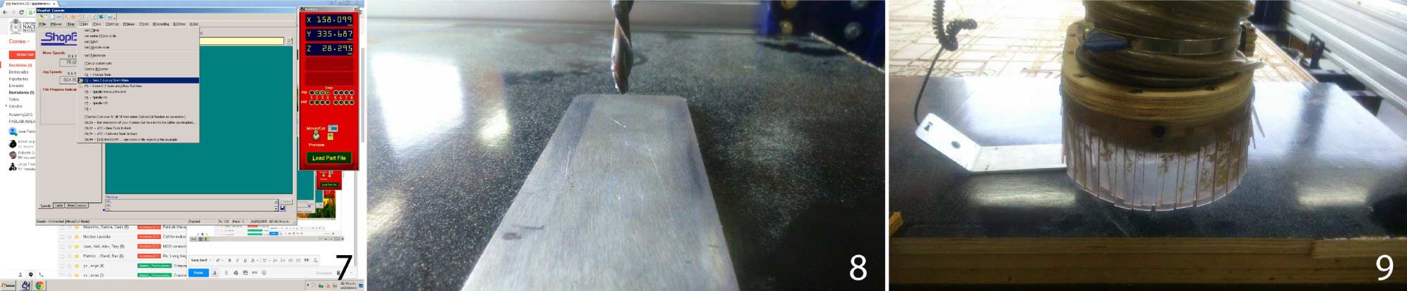
- 6. Cuts > C3_ Home XY Axis Using Prox Switches.
- 7. Cuts > C2_Zero Z axis w/ Zero Plate
- 8. ALWAYS PUT THE ZERO PLATE IN IT PLACE BEFORE ENTER.
- 9. The Machine will set Z.
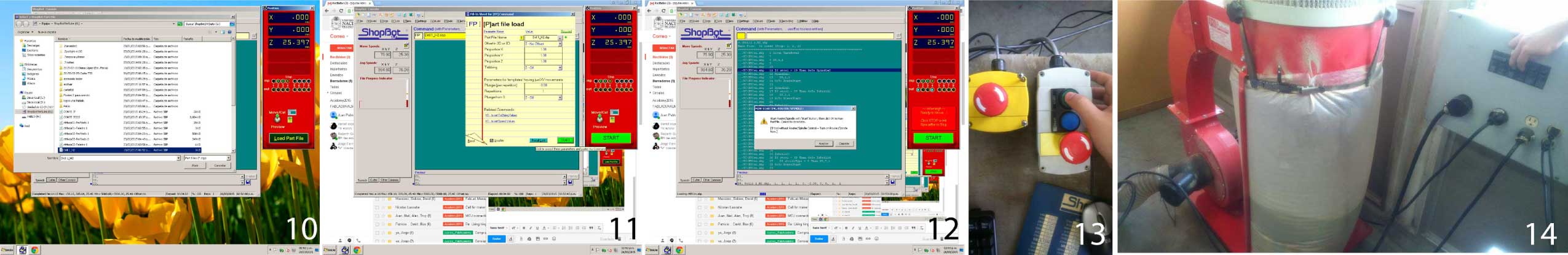
- 10. Load Part File and Open your file.
- 11. Press Start.
- 12. The Software will ask to Star the spindle before.
- 13. Press Start ( The green button ).
- 14. Turn ON the Extractor.
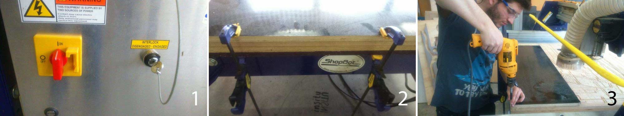
ALWAYS USE THE SAFETY ELEMENTS!(GLASSES, GLOBES AND EAR PROTECTION)
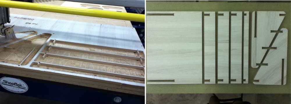
Cut and Assembly Process
As I already said I used a leftover piece of sheet of MDF Melamine Coated +/- 15 MM thickness, to make the notebook stand. In order to properly cut the element, you always need to do the previews steps.
Desk
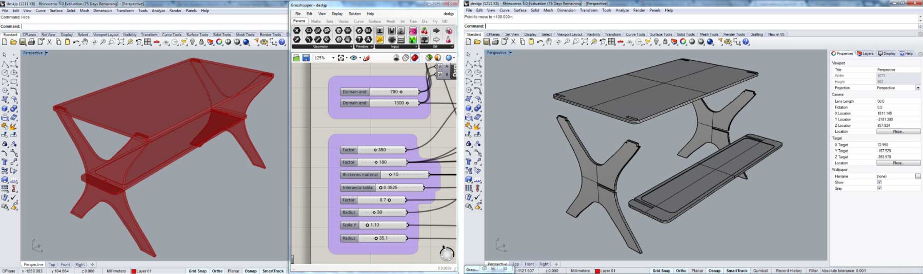
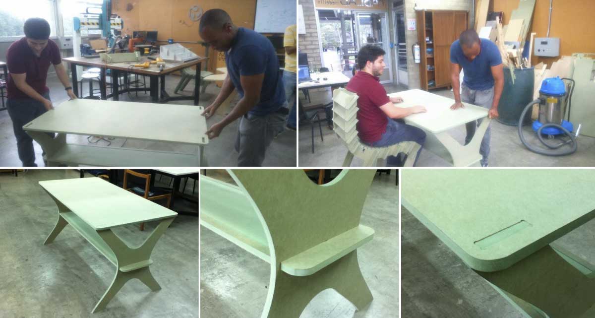
Continuing with the idea of prototyping self_assembly furniture I decide to make a fully parametric desk that could be modify in its basic dimensions and depending on the material too. With some advice of my partner Daniel Asprilla, I achieve a series of parameters to be controlled before manufacturing the element. The desk was entirely developed in the Rhino plugin Grasshopper.The desk design consists in 2 side pieces and 2 useful surfaces.
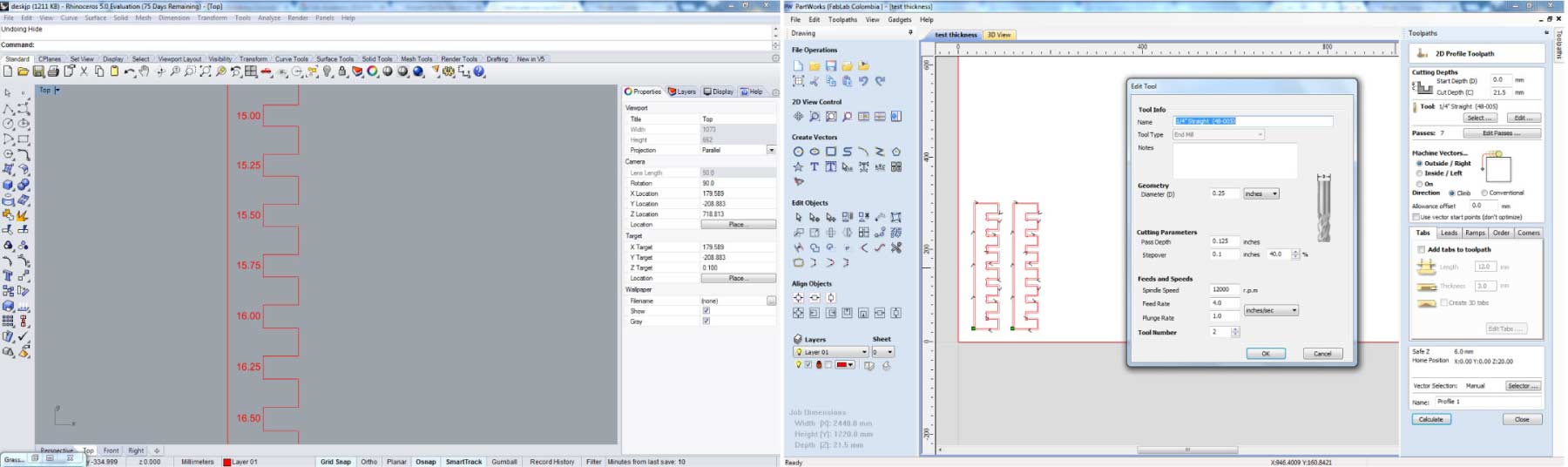
Tolerance Test
For both (the notebook stand and the desk) I made tolerance tests looking forward the best press-fit. The result was more or less .35 mm in each side for a precise joint. The one that works for me was 15.75mm in a 15mm sheet. The parameters for cutting the tolerance test with a ¼ bit were:
- Spindle Speed _ 12000 rpm
- Feed Rate_ 4.0 inches/sec
- Plunge Rate_ 1.0 inches/sec
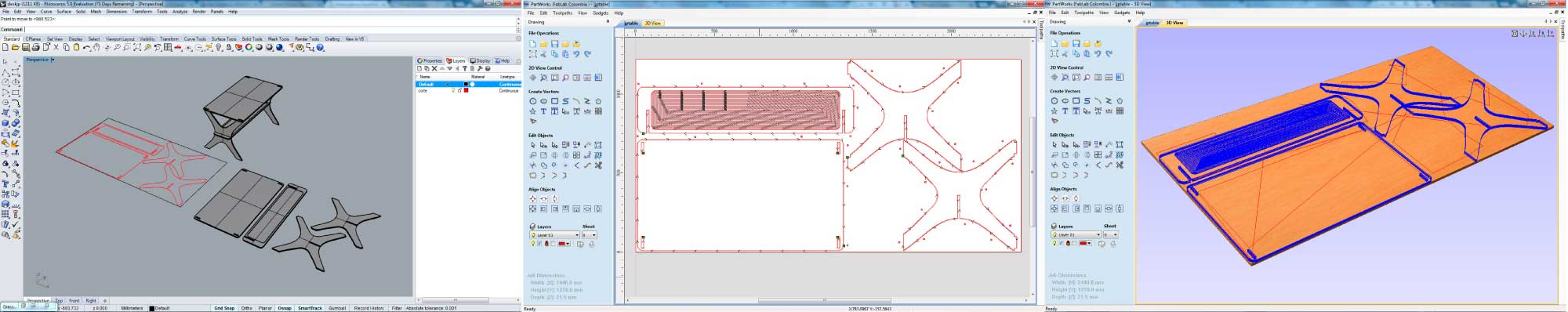
Fabrication Process
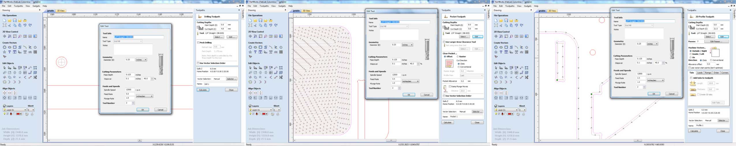
As I explain before we have to nest all the curves in the “sheet” and export it like default dfx. The sheet used was a 15MM HR_MDF. On this element I set 3 toolpaths to cut the element. The first was a Drilling Toolpath. 3MM for cut depth, The tool used was a ¼ bit. The parameters were:
- Spindle Speed _ 12000 rpm
- Feed Rate_ 5.0 inches/sec
- Plunge Rate_ 1.0 inches/sec
I also explore the Pocket Toolpath in one piece. The cut depth was 3MM with a ¼ bit. The parameters were:
- Spindle Speed _ 12000 rpm
- Feed Rate_ 3.5 inches/sec
- Plunge Rate_ 1.0 inches/sec
Finally to cut the pieces with a ¼ bit in a 21.5MM cut depth the parameters were:
- Spindle Speed _ 12000 rpm
- Feed Rate_ 3.5 inches/sec
- Plunge Rate_ 1.0 inches/sec
Cut and Assembly process
As we all know the bits are circular, and if you want to reach 90º corners you need to make “dog bones” or “t-bones” in each corner to fit every element well.
This week assignment was great to get to know better the machine and all the process involved in each element, the precautions and all the safety conditions to make something. One of the most important things to take in count is the tolerances between elements, that’s the “secret” to have a strong and solid element.