Final Project
1. Concept and Poject Management
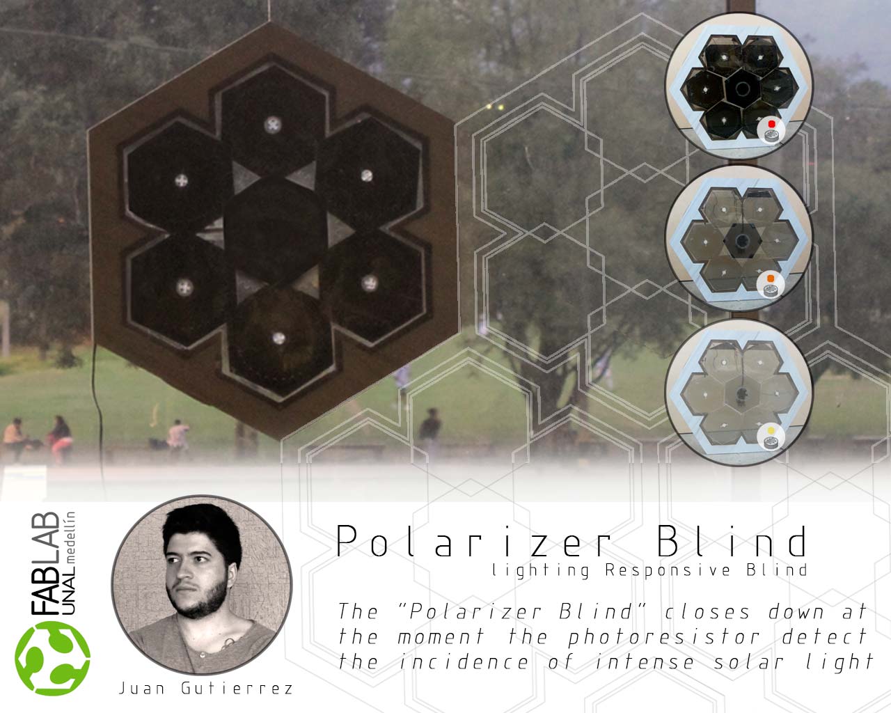
Lighting Responsive Blind
General Description of the Project
My primary interest is responsive architectural systems, the fab academy has been a great opportunity to explore some kind of systems that goes behind of facade elements. In the last decades there is an increasing concern in sustainability, energy saving, and climatic change. As response to all this concerns, the new trends in kinetic architecture and domotic architecture are taking an important role nowadays.
A building envelope must transcend its role as a simple protective wrapper and “understand” all the forces that act in itself (climatic, information, human agents) and response in the best way. Sensors, actuators, “smart materials” allows a new experience where the architecture adapts to humans.
Along the assignments particularly in inputs and outputs I explored the motion through servomotors, with potentiometers and photoresistors as inputs. I also did some material explorations that gave me a whole new perspective of my final project.
What does it do?
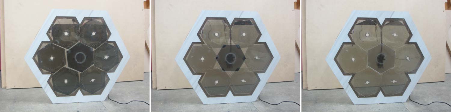
The “Lightning Responsive Blind” reacts depending on the amount of light in the environment. It can provide shadow or let light pass making the interior ambient comfortable.
Who's done what beforehand?
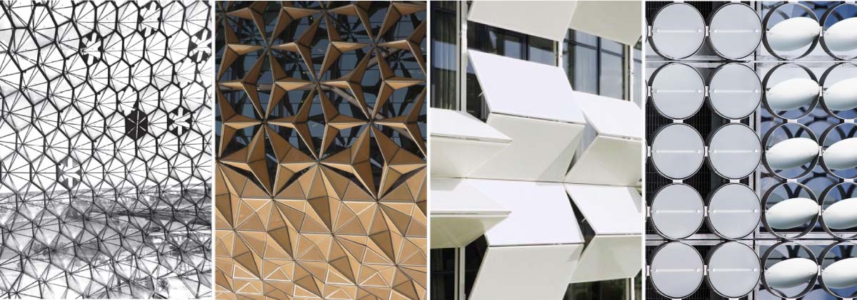
As I said before, in the last decades there has been an increasing interest in responsive (or adaptive) architectural systems. There are several projects, but for me one of the most representative in an industrial and constructive scale are:
- >Montreal Expo Dome_Buckminster Fuller(1967)
- >Al Bahar Towers_Aedas(2012)
- >Kiefer Technic Showroom_Ernst Giselbrecht + Partner ZT GmbH (2007)
- >Rmit Desing Hub_Sean Godsell Architects (2012)
In a Fab Academy Scale:
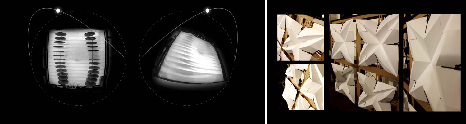
- >Building Gestures_Efilena Baseta (2014)
- >Lighting Responsive Origami Facade_Robert Garita/Alejandra Diaz de Leon/Mauricio Valenzuela/Aldo Sollazzo (2013)
What materials and components were used?
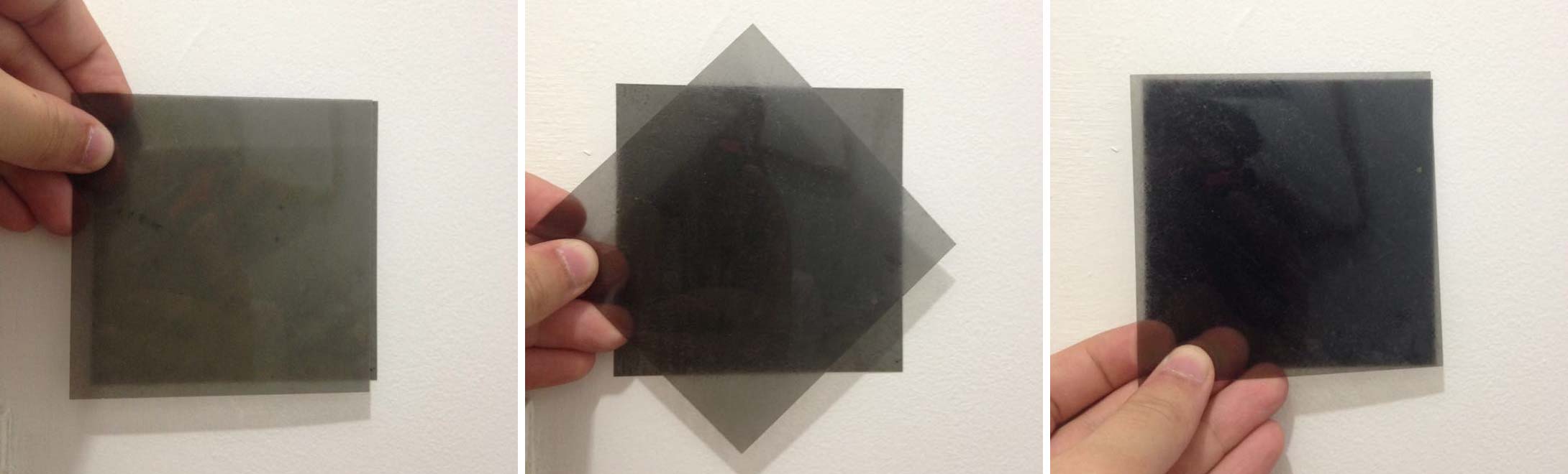
The past weeks I discovered with help from Sebastian Ocampo the Linear Polarizer. That gave me a new perspective of the final project. The Linear Polarizer has been a hard to get material in my city but there are a few ways to get it. An old damaged monitor is a good option to get two Linear Polarizers. The second option is buy it on internet but I have to take in account the time of the import.
The other electronics and mechanical parts detailed next are available in my city or in our Lab.
Where did they come from?
As I mentioned above, all the electronics were available on our lab, some other materials are easy to get in our city.
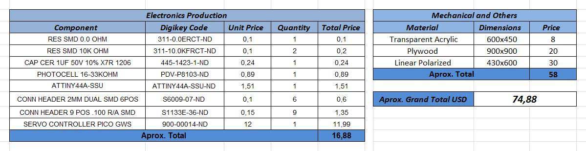
How much did they cost?
Around $75 USD. But the costs can be considerably reduced if it is made with recycled materials (the linear polarizers of an old damaged monitor) and wood left-overs of our lab.
What parts and systems were made?
- >Mechanical System.
- >Wooden Structure.
- >Servo + Photocell Board.
- >Connectors and assembly system.
What processes were used?
- Project Management
- Computer-Aided Design
- Computer-Controlled Cutting
- Electronics Design
- Electronics Production
- Embedded Programming
- Computer-Controlled Machining
- Input Devices
- Output Devices
- Mechanical Design, Machine Design
What questions were answered?
At first I was in doubt if the mechanical system would work well with the servo, if the servo could turn the panels in a specific position , among others, but certainly everything works fine and I have a working prototype.
How was it evaluated?
Solve an architectural system involves several systems in itself. The resolution of a building skin is related with the dynamics of the building. The interior comfort, the ecological footprint, the operation cost can be radically reduced with the building envelope. A very simple solution but with tons of potential to be developed in other scales. The prototype must work properly in all its parts and be able to respond efficiently to the place needs
What are the implications?
The idea to start with this research is to keep developing this and other prototypes with new materials, new mechanical systems and new sensors before take them into a business.
2. Fabrication Process
Model 1.0_Firts Prototype
Design
This was the first model of my final prototype were I tried to synthesize all the ideas that I had along this weeks. The result was the base of developing the whole process. The learnings and the discoverings in this prototype were fundamental to solve and debug the final project.
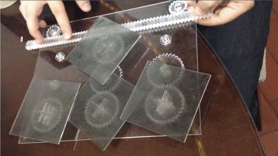
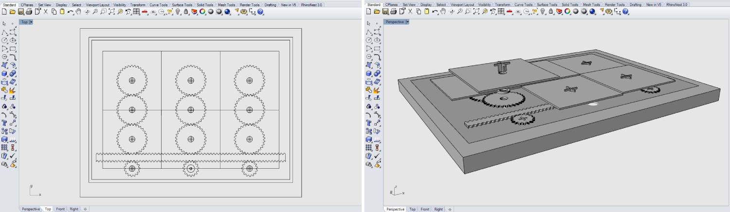
I started with a basic model in “Rhinoceros”. This is one of the CAD software with which I feel more confident. The system consisted in a basic rack and pinion that allows me to rotate the polarizer panels in a circular motion from the linear motion of the rack.
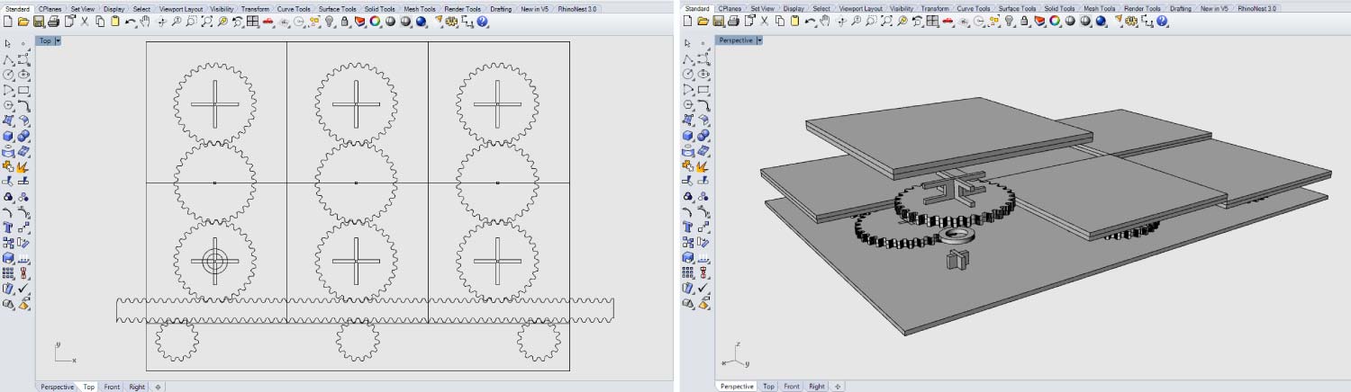
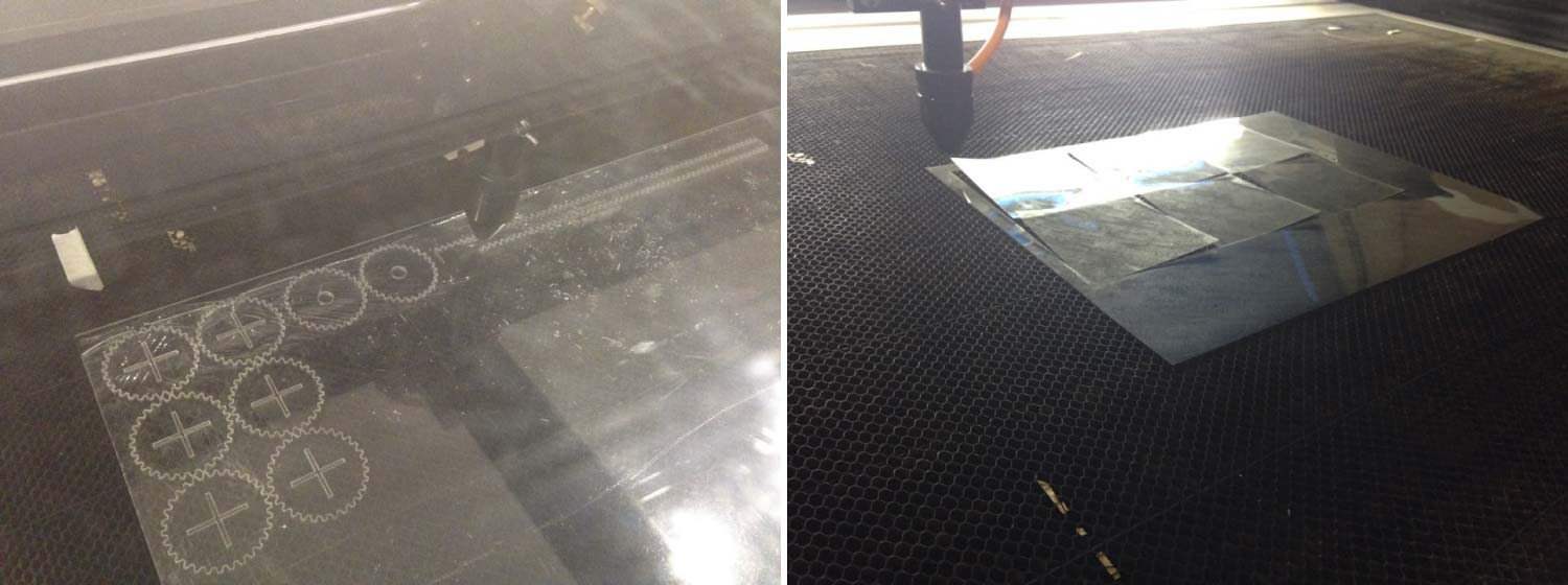
I quickly jumped to computer controlled cutting. I decided to make a first prototype that was not completely solved. As Neil said in Invention, intellectual property and income lecture, “ready, FIRE, aim”. Don’t wait to fabricate until you have totally resolved your project. Rapid prototyping it’s the best option to learn in the way. Almost every part of this prototype was 2mm “Cast Acrylic Clear” and linear polarizer.
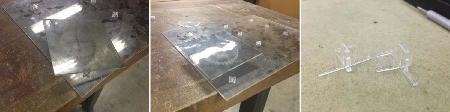
As I said before I “fired” having a lot of things to solve, but this prototype helped me to have things clear, realize what parts were not working correctly and think how to make it work. The images below are pretty clear, I had to work hard to correct all the mistakes of this model. Major errors of this model were: the joints were too fragile, the panels were not enough close to the base and the polarizer effect was not as I imagined. The panels were no attached to the base and fall down . The axis didn’t were aligned... among others.
Model 2.0_Second Prototype
Design
With the first prototype I could improve a lot of things, the number of parts reduced radically, and the system itself works better. I continued drawing in “Rhinoceros” thinking in on how to make a module that could be associated with others modules.
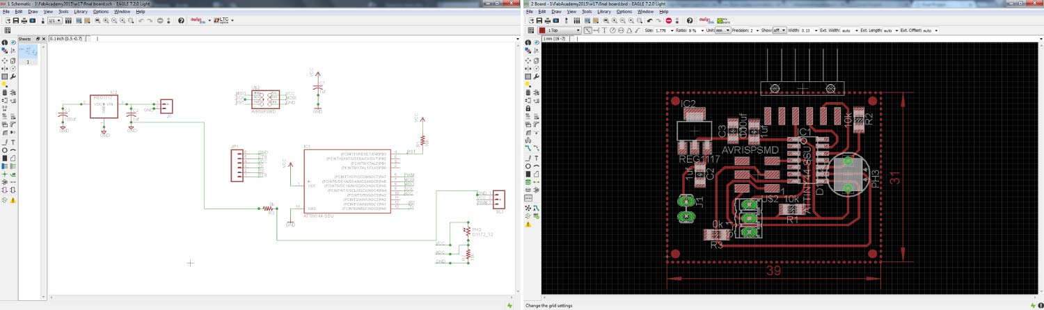
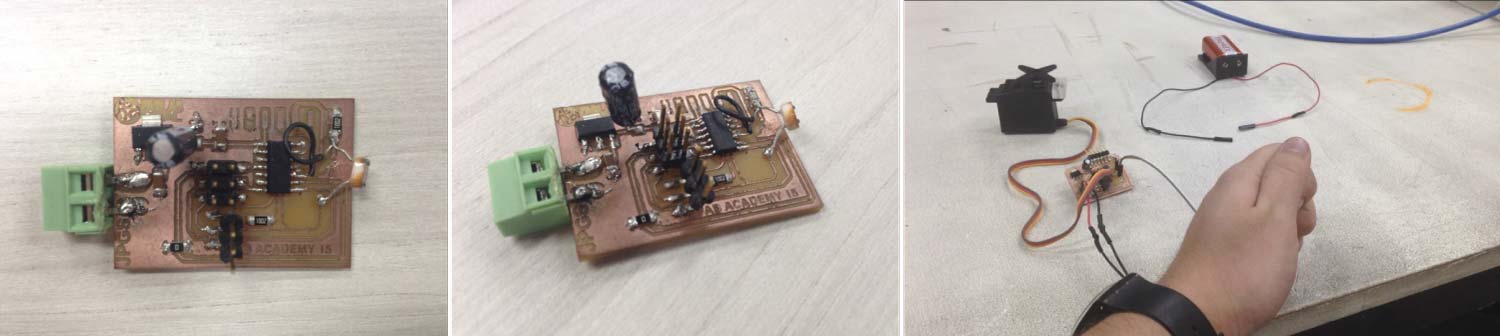
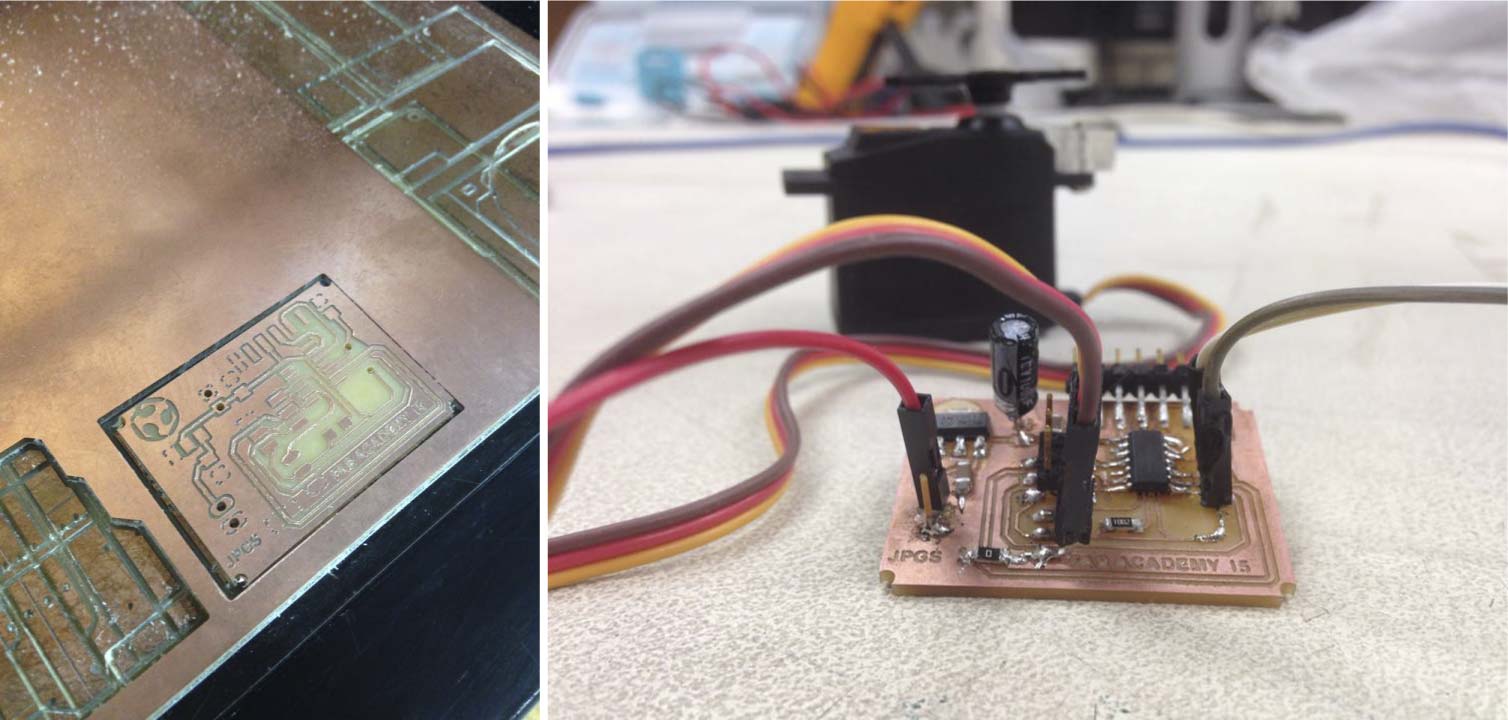
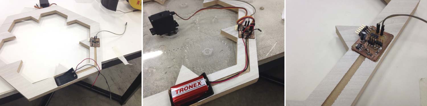
In Week 10 (input & output devices) I moved a servo with a photoresistor as input. That board was the base of the final board. The components remained the same but I added a few components to connect the whole system to a 9v battery or a battery charger in any outlet. I added the next components: (1) REGULATOR 1117 5v, (1) CAPACITOR VALUE 100uf and (1) CAPACITOR VALEU 1uf.
The next step was to milling the board. I used the same parameters that have always worked for me.
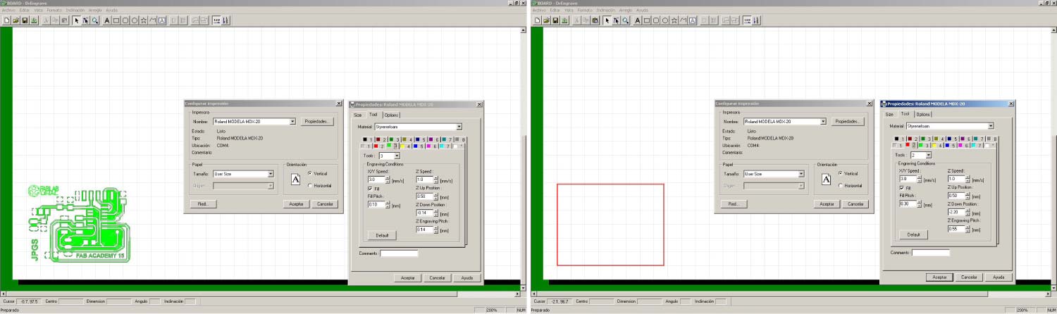
The soldering process was a bit difficult because I used a busbar (to provide voltage to the board) a little bit big for the board, and i have to solder it in a non-conventional way. Latter I changed to a double pin and that solve my problems.
Code
 /*
 Juan Pablo Gutierrez Salazar Attiny code for servo controlling
 with help from Daniel Pineda and Manuela Bermudez.
 June 2015
  */


int analog1 = 3; //Analog Input
int pwm1 = 7; //PWM Output
int i = 0;

void setup(){

  pinMode(analog1,INPUT);
  pinMode(pwm1, OUTPUT); //pinmodes
}

void loop(){

  int an1 = analogRead(analog1);
  int pwmServo = (int)((255.*an1)/1023.);
  analogWrite(pwm1, 1023); //set pwm
  delayMicroseconds(pwmServo);
  analogWrite(pwm1, 0);
}
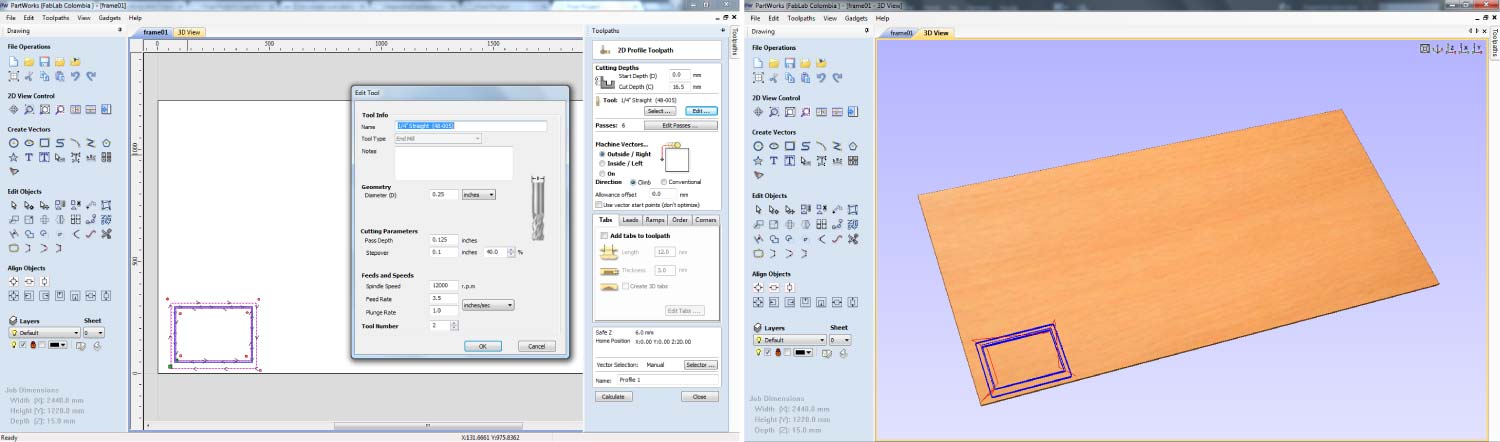
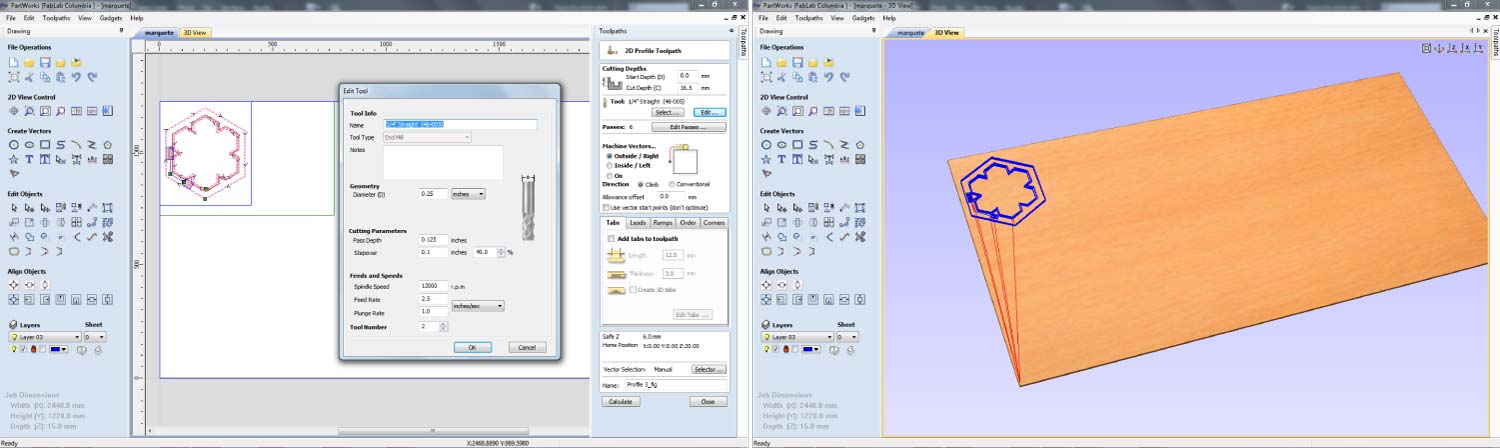
I decided to make a frame in the Shopbot CNC machine; I used a leftover of 15mm MDF. The bit I used was a ¼”. The framework had a pocket that allows the acrylic coupled with it.
The GIFT bellow shows the prototype working. The panels rotate with some difficult because the joints were not enough loose.
As you can see, the second prototype had a lot of improvements; it acquired complexity and shape. But had a lot of work to do before becoming the final model.
3. Final Prototype
Design
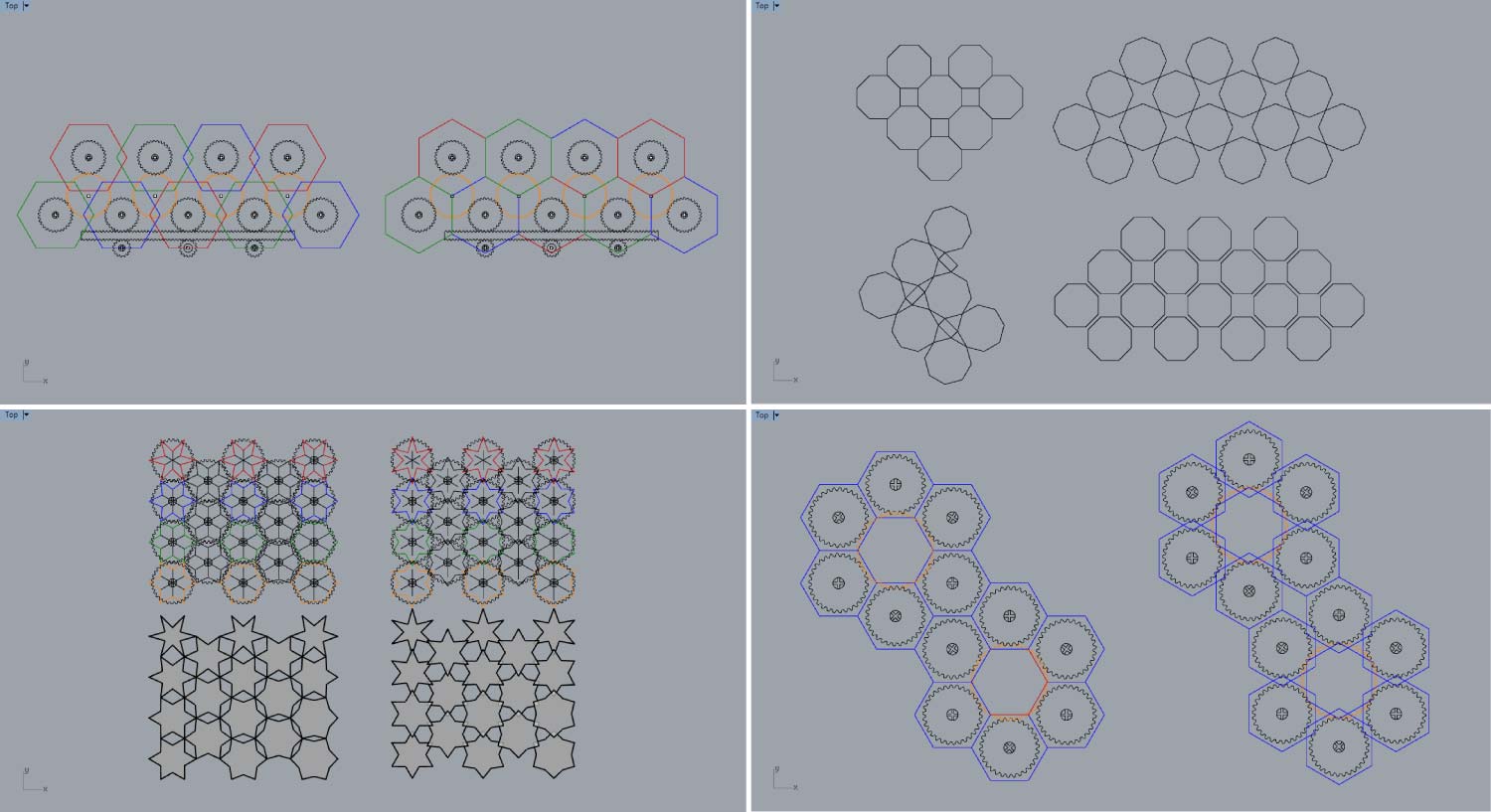
I had a system that worked, but there was something missing, the shape was not good enough and the system worked but it could be more efficient. By recommendation of my local instructor I started all over again. The purpose was clear; achieve a modular shape with more “formal richness”. I started by looking for tessellations, and any other modular shape that could be used in my final project.
In the image bellow can be seen a few the explorations that I made using “Rhinoceros”. At the end I used a hexagon module.
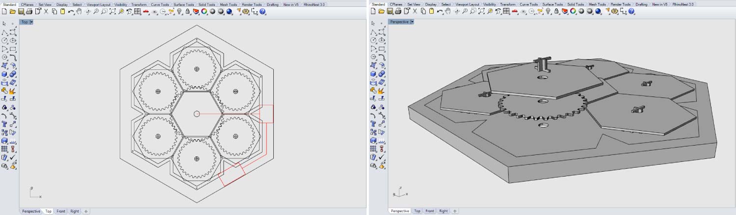
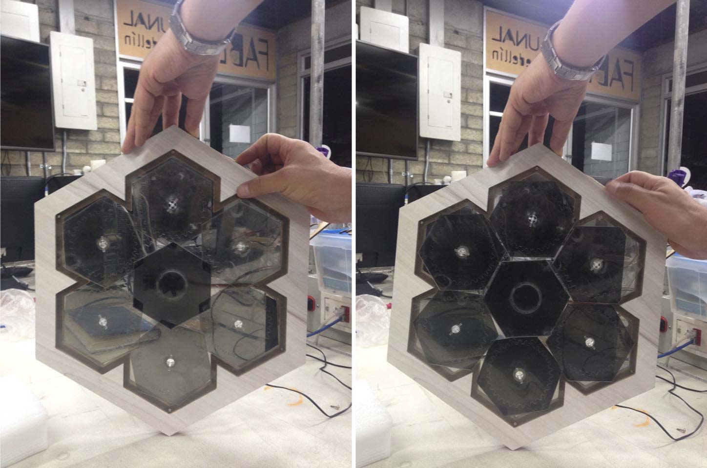
The basic system remains nearly the same, a planetary gear works even better than the rack and pinion of the first two prototypes. With some improvements in the joints the panels rotate pretty well. I used the software called Gear template generator for the pinions.
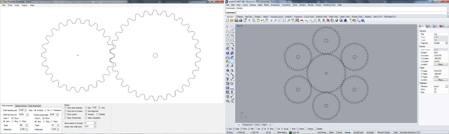
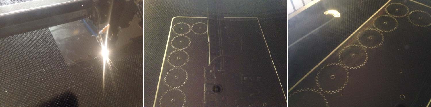
For the final prototype I worked also with 2mm “Cast Acrylic Clear” and linear polarizer. The reason to use the Acrylic Clear was because it is similar to glass. It is Weather-resistant; it’s resistant to mechanical stress, 100% recyclable among others. I used laser cutter to cut the basic gear system and the linear polarizer.
I also made a new board with 2 pin heads to connect the 9v battery or the charger. I also connected the photoresistor to the board with 2 jumpers in order to have the input device in the front of the prototype.
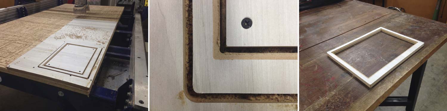
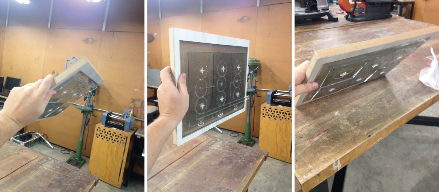
The framework took a new meaning in this prototype. I made a double sided frame with the CNC shopbot machine. I used a leftover of 15mm MDF available in our lab and cut it with the same parameters of the previous one.
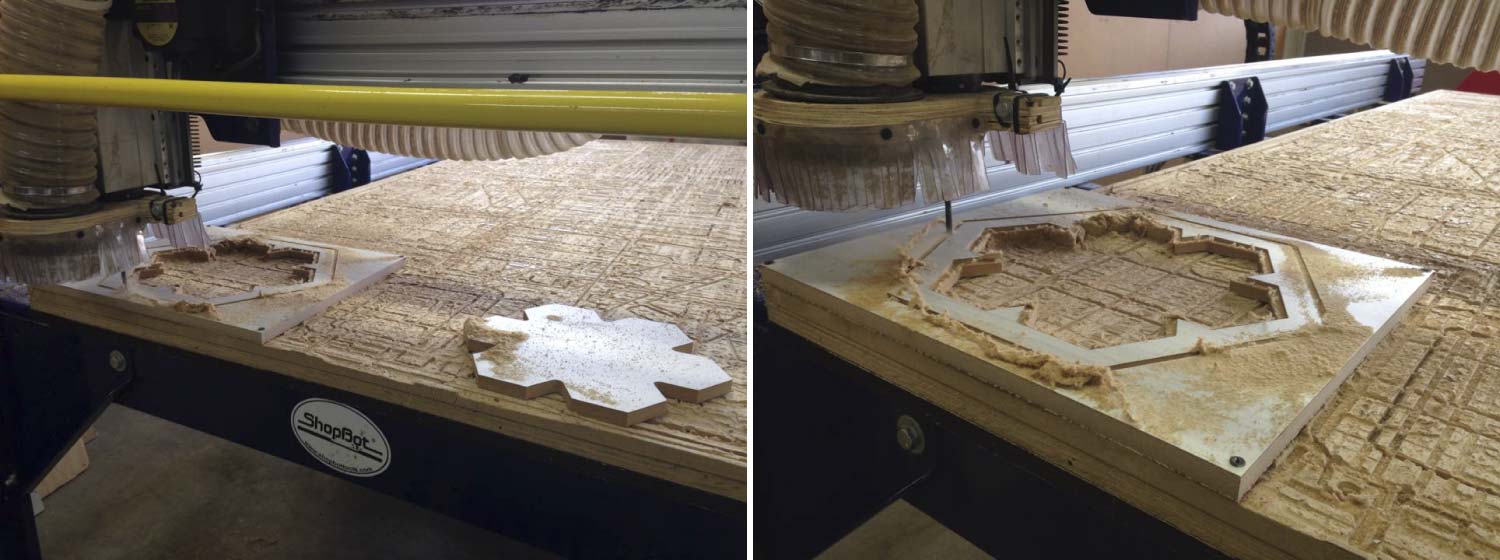
In the images bellow you can see what I mentioned above, the frame was milled in both sides. The front side had the pocket were the acrylic fits, and the back side has also pockets for the board, the cables and a 9v battery adapter.
The final prototype works pretty fine, the movement is fluid, the polarizer effect is clear and the input and output fulfills their role.
This final prototype does not end here my expectations are to continue improving it and fabricate new ones. There are a few things that could be improved to make the system more efficient.