Networking and Communications
Week 13
Review
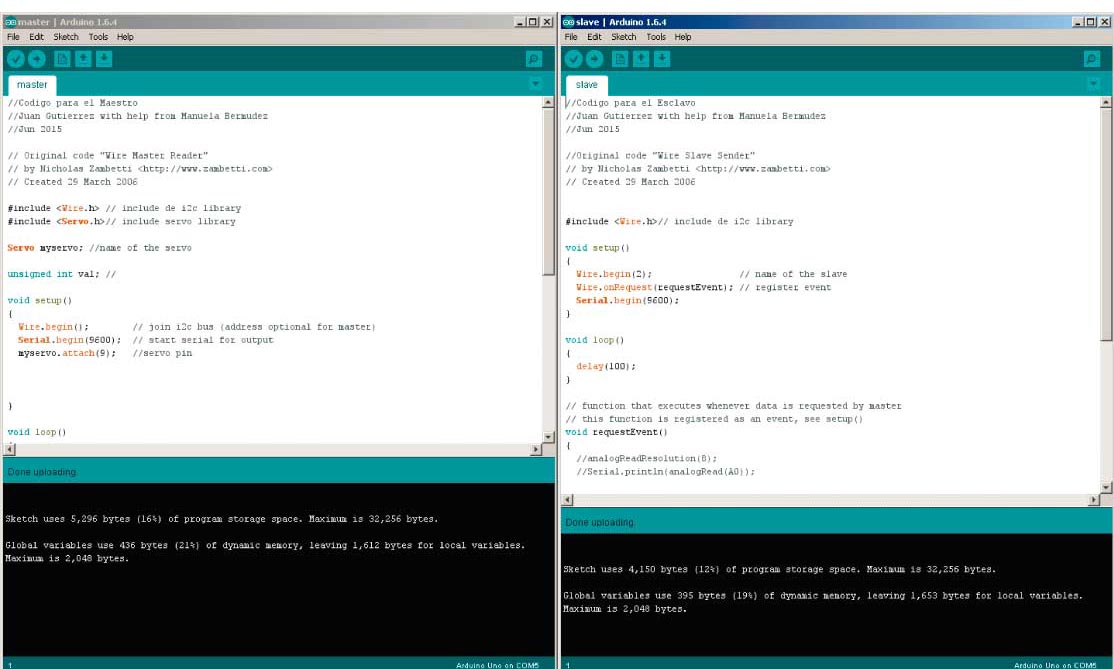
I have to admit this week’s assignment was one of the most difficult for me. We decide to make the Fabduinos with help from our local physics students monitors. This week purpose was to move a servo with a potentiometer using one board as a “Master” and the other as a “Slave”. The boards are programmed to communicate each other via i2c serial protocol. The Arduino “Wire.h” library was used to accomplish the communication.
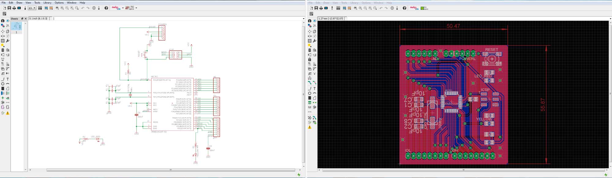
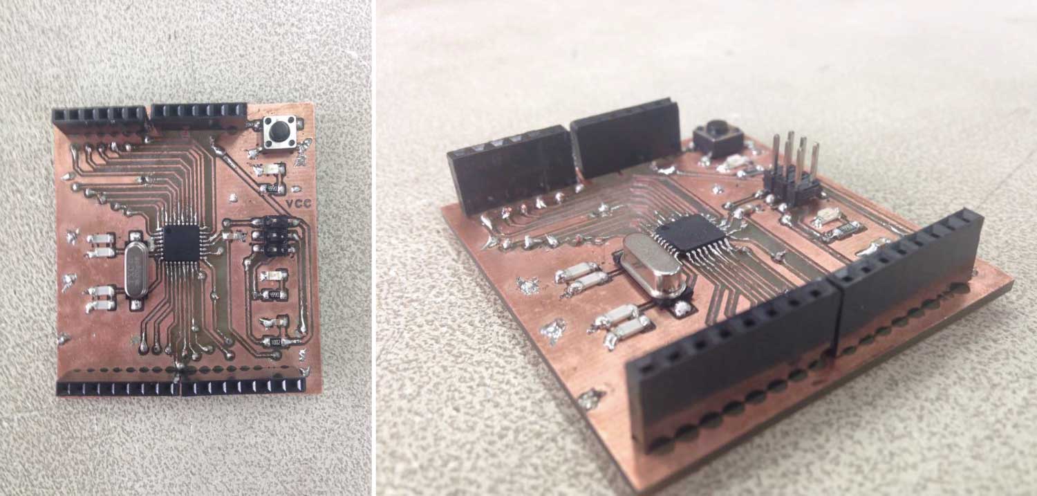
FabDuino Design
We have to make a decision of which FabDuino fabricate. At the beginning we look up the Satshakit version but at the end we decide to make our own Fabduino. Our version resembles the Arduino UNO in dimensions and also in the pin disposition. The result was a double sided PCB.
The required components are:
- (1) ATMEGA328P
- (1) CRYSTAL 16 Mhz
- (1) LED_GREEN
- (1) LED_RED
- (1) SWITCH/BUTTON
- (1) RESISTOR VALEU 10K
- (2) RESISTOR VALEU 449
- (4) CAPACITOR VALEU 10pf
- (2) CAPACITOR VALEU 100nf
- PIN HEADERS
Double Sided PCB in the Roland MDX-20 Machine
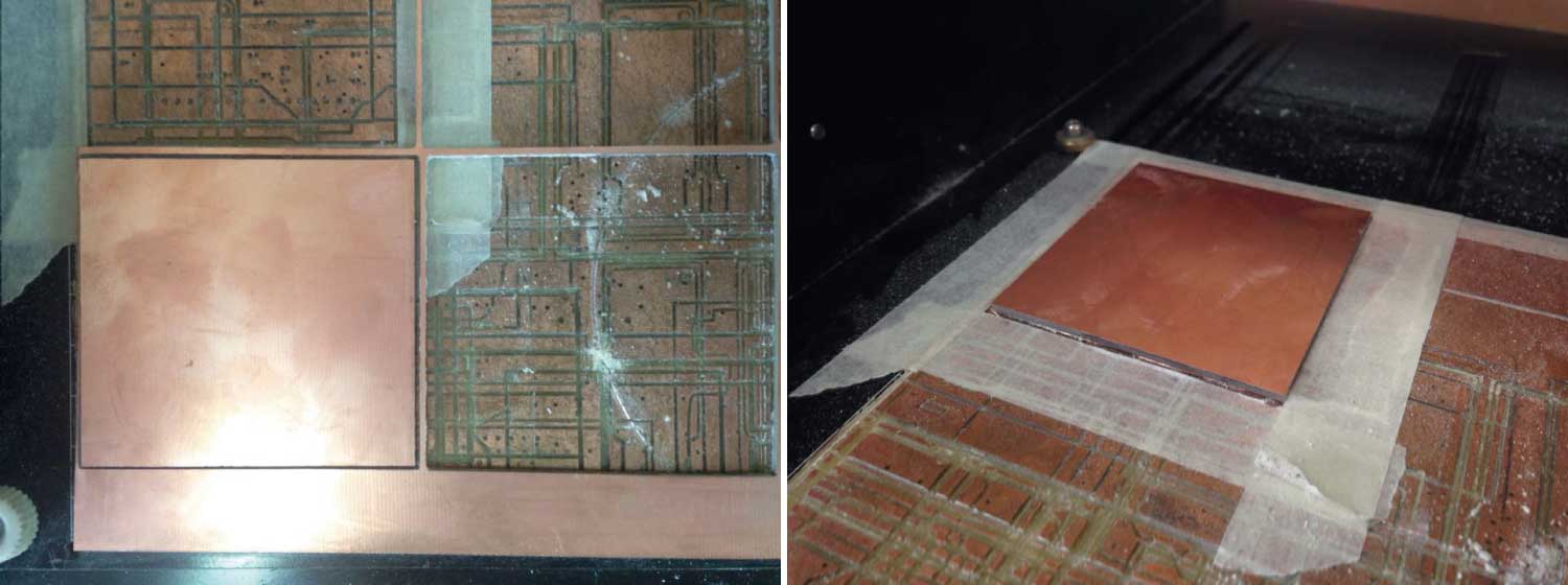
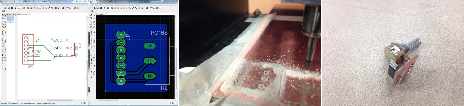
The next challenge was milling the board. The way we planned to fabricate the board worked pretty well. I will try to describe the process the best I can. The first step was to cut the cupper board in a perfect rectangular shape (in our case); big enough to work with it. The reason to do this is because the cupper board sometimes has an irregular shape that could affect the milling process.
The next step is milling that rectangular shape in a “sacrifice bed” in order to place the boards that will be milled aligned to the corners. Use enough tape to fix the board to the “bed”.
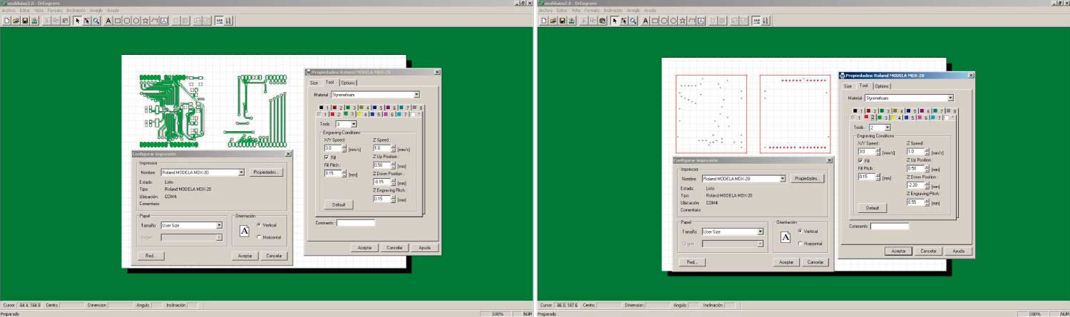
Milling
With the board correctly placed the next step is milling with the same parameters that have always worked for me. One important thing is to control the position of the board in the software work space. Having a reference point to position the boards is fundamental to achieve precise results.
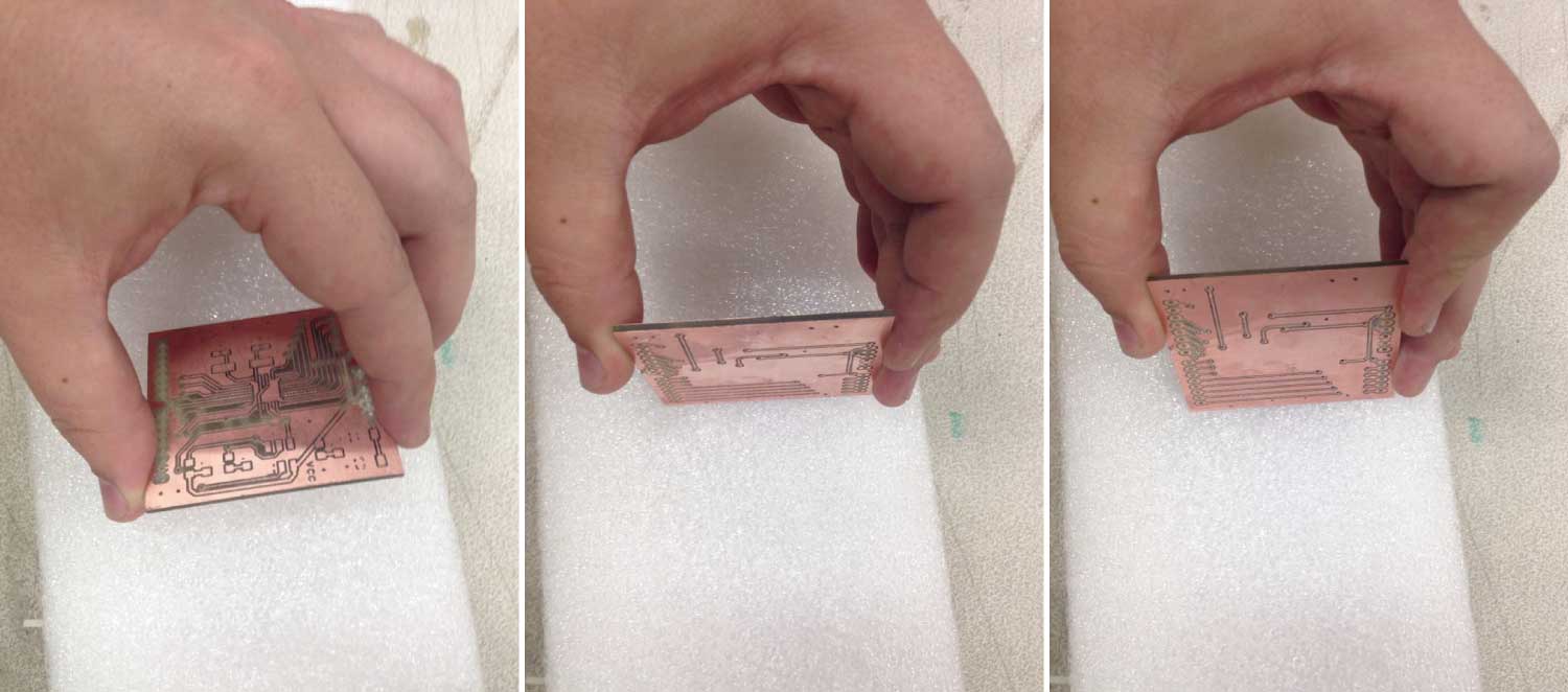
Mill the first side and also make the holes. When it’s finished rotate the board trying to align it perfectly with the corners. Make a ”hole test” trying to mill the same holes from the other side. Mill the bottom side and there you have it. The precision depends on how careful you were placing the board.
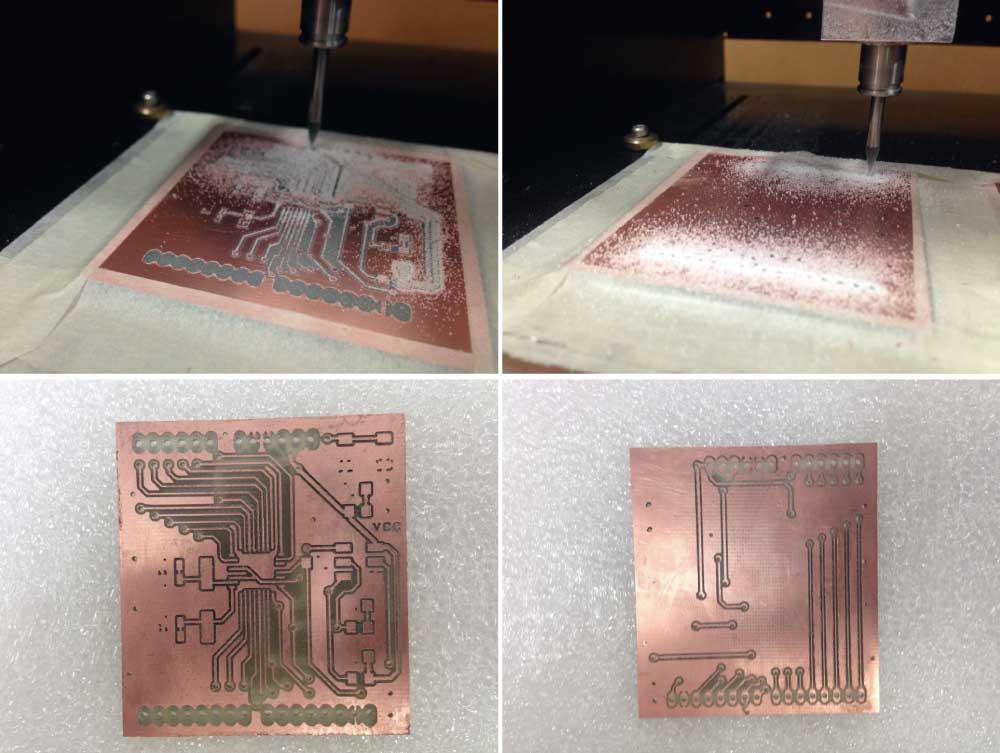
The precision depends on how careful you were placing the board.
Soldering
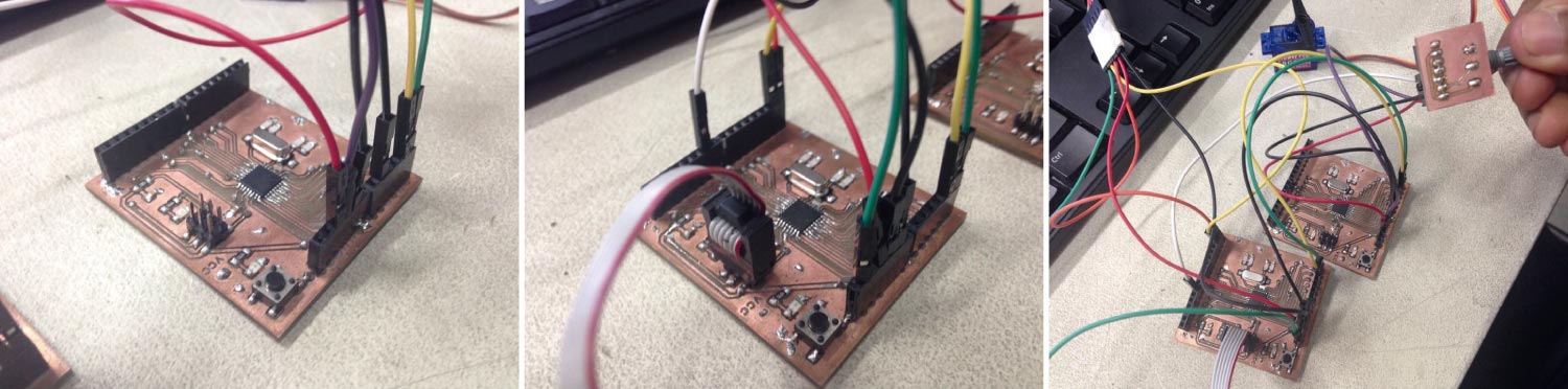
Once the board is soldered we are ready to program it to work as an Arduino. It is necessary to upload the Arduino Bootloader. I made a very easy board with a potentiometer as an analog sensor to control the servomotor through the fabduino.
Arduino bootloader
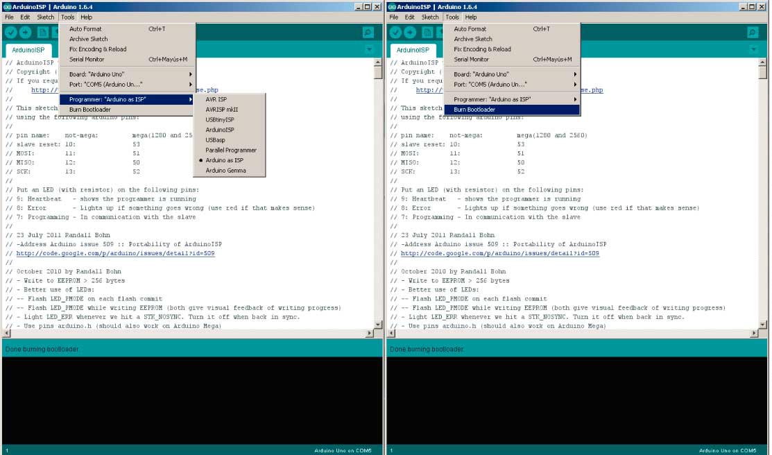
There are two ways to program our FabDuino; one is with the fabISP, the other one is with another Arduino. Once everything is connected follow the next steps:
- 1. Open Arduino IDE
- 2. Select proper programmer by clicking on Tools->Programmer Arduino as ISP
- 3. Select Arduino UNO as Tools->Board
- 4. Click on Tools->Burn Bootloader
I2C
As I said before I worked with the Wire.h library and followed this tutorial. The I2C protocol involves using two wires to send and receive data: a serial clock pin (SCL) that the Arduino pulses at a regular interval, and a serial data pin (SDA) over which data is sent between the two devices. As the clock pulse changes from low to high (known as the rising edge of the clock), a bit of information containing the address of a specific device and a request for data, is transferred from the Arduino to the I2C devices over the SDA line. When the clock pin changes from high to low (the falling edge of the clock), the called upon device transmits it's data back to the Arduino over the same line.
The 12C protocol allows for each enabled device to have it's own unique address, and as both master and slave devices to take turns communicating over a single line, it is possible for or FabDuino to communicate (in turn) with other FabDuinos, while using just two pins of the microcontroller.
Master_Code
//Master_Code based on "Wire Master Reader" by Nicholas Zambetti
//Juan Gutierrez with help from Manuela Bermudez
//Jun 2015

#include <"Wire.h"> // include i2c library
#include <"Servo.h">// include servo library

Servo myservo; //name of the servo

unsigned int val; //

void setup()
{
  Wire.begin();        // join i2c bus (address optional for master)
  Serial.begin(9600);  // start serial for output
  myservo.attach(9);   //servo pin
}


void loop()
{
  Wire.requestFrom(2, 6);    // request 6 bytes from slave device #2
	if(Wire.available())    // slave may send less than requested
  {
    byte c = (Wire.read());  // receive a byte as character
	val = (c*180);
    val = (val/255);

   Serial.println(val);

   myservo.write(val);
   delay(15);
  }
}
Slave_Code
//Slave_Code based on "Wire Master Reader" by Nicholas Zambetti
//Juan Gutierrez with help from Manuela Bermudez
//Jun 2015

#include <"Wire.h">// include i2c library

void setup()
{
  Wire.begin(2);                // name of the slave
  Wire.onRequest(requestEvent); // register event
  Serial.begin(9600);
}

void loop()
{
  delay(100);
}

// function that executes whenever data is requested by master
// this function is registered as an event, see setup()
void requestEvent()
{

  Serial.println(analogRead(A1));
  long sensorValue = analogRead(A1);
  sensorValue = (sensorValue*255);
  sensorValue = (sensorValue/1023);

  byte a = sensorValue;
  Serial.print(a);

  Wire.write(a);              // send the lower 8 bits

}