

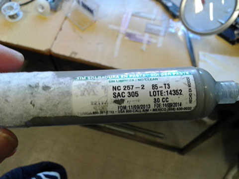
If we recapitulate last lesson, Electronics Design, I was trying to use a mask to apply solder paste to my circuit.
I used small pieces of carton and plastic as mask to aply solder. Thin plastified carton (left), thick plastified carton (red) and thick plastic. I also used a small mdf piece to align and support my board. Nothing worked.
I ended up exercising my poor soldering skills and did my board by hand.
But I didn't give up and kept experimenting until succeed
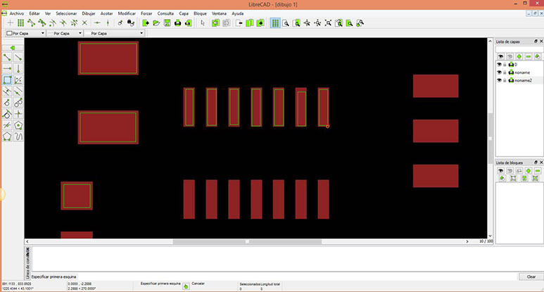
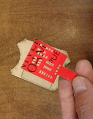
The first thing is to design the mask layout out of my eagle board design to laser cut it. To do this I used Librecad and draw squares where I wanted to deposit soldering paste. Have to be very careful here because when importing an image to librecad the program considers pixels as millimeters so after drawing I had to scale the design to proper measures.
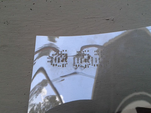
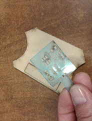
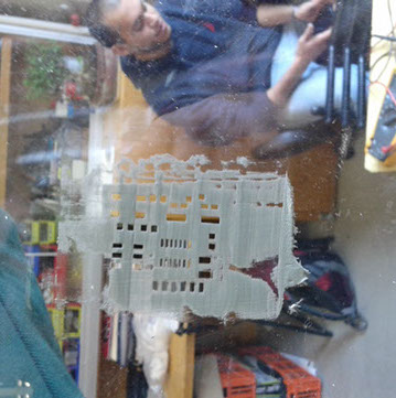
Then I used a sheet of acetate and laser cut it.
I made several tests. The material burns very easy and good trails are hard to achieve.
Finally in our machine we use a speed of 200 with 15% power to perfectly cut the design.
Later we found out that these traces can be cut with the vinyl cutting machine using a sticky surface to fix the acetate sheet.
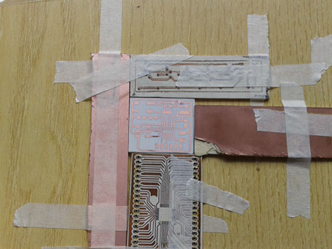
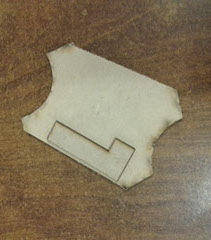
The second step is to fix the board in place. To do this I used several used boards and fixed them with masking tape.
Last time our Modela's tool broke so we made some boards with traditional methods so I used one of those. Later we got the tool and build the board properly
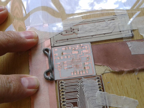
The third step is to align the acetate cuts with our board cuts and fix the acetate firmly with the hand.
Then apply generous amount of soldering paste and give two passes with a putty knife.
The first pass is gentle, trying to apply a big amount of paste making sure to fill all the mask's holes.
The second pass has to be firm to leave paste only in the holes.
Then carefully remove the acetate trying not to smear the soldering paste on the rest of the board
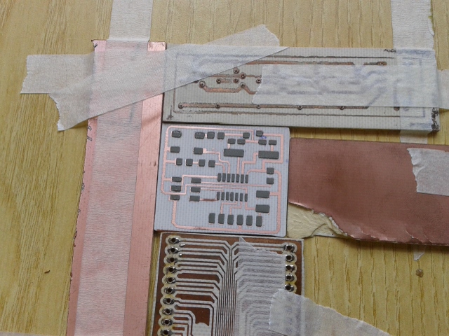
Voilá, The soldering paste is in place.
I made the mistake to cover every trace with paste and it was only necessary where the SMDs goes. So I took off all extra soldering paste from my board.
WARNING: if you remove soldering paste from a Modela made board, soldering paste will go between your copper lines and it will be very hard to remove the paste inside the small canals.
Then I installed the components and baked the board in our oven at 375 F for 1 minute. You can tell it is soldered when paste changes and looks shiny.
Later we found out you can bake your board with a heating gun or directly on a pan. Be careful not to toast your board or components.
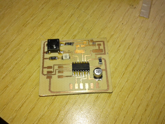
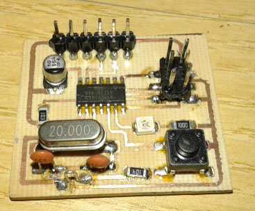
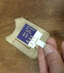
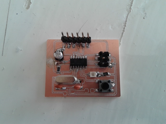
Finally the board is ready with the rest of the components
Programming
One member of Fab Lab Puebla, Huber Giron, found a way to use an Arduino board as an ISP.
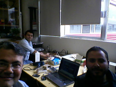
He helped us to implemented the steps from the video on our Saturday morning meeting.
The first step is to load ATTINY libraries to my Arduino IDE. We found it works on older versions of Arduino IDE. Mine is 1.0.5 and it works perfect.
You have to copy the folder containing the libraries into the Arduino/hardware folder.
You can find the Arduino libraries folder Here.
Second it is necessary to install winavr. You can download it Here
WinAVRTM (pronounced "whenever") is a suite of executable, open source software development tools for the Atmel AVR series of RISC microprocessors hosted on the Windows platform. It includes the GNU GCC compiler for C and C++.
WinAVRTM contains all the tools for developing on the AVR. This includes avr-gcc (compiler), avrdude (programmer) and avr-gdb (debugger). The Arduino as ISP program uses WinAVR to program the ATTINY 44
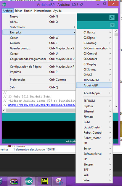
Third step is to load to your Arduino board the Arduino ISP program.
It can be found in the Menu --> Archive --> Examples --> Arduino ISP
Once it is loaded it allows our Arduino Board to program other boards.
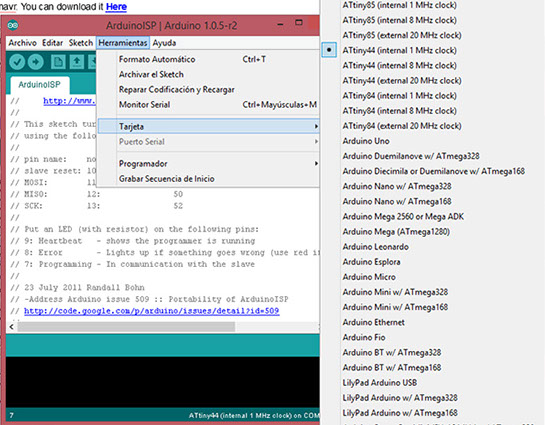
Next in the Arduino IDE you have to open Menu --> Tools --> Board, and choose the Attiny44 microprocessor.
After these steps, your Arduino is ready to connect your board for programming
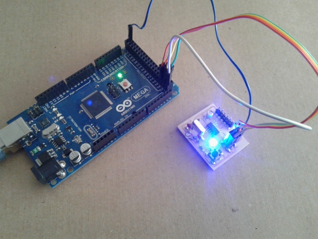
Now you are ready to connect your board to the Arduino.
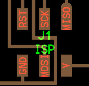
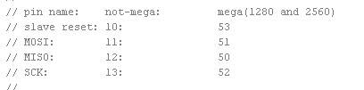
When you open the Arduino ISP program you can read the order of connections as seen below.
You have to connect your board at pins 50 to 53, MISO, MOSI, SCK and RST.
You take Ground and Voltage from the Arduino board also.
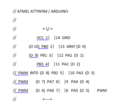
Now we are ready to program. In order to do it properly you have to consider the pin number from the image.
Since my board has the button on pin 6 and the led on pin 5, when programming I have to name this pins as 7 and 8.
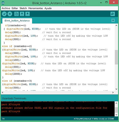
To make my program I started with the Blink example located in the menu Archive --> Examples --> Blink
Then I modified it to work as a push button counter from 1 to 5.
One push button, led blinks once at the time. Two pushes, led blinks twice and so on until it reaches 5 when counter resets its number to zero.
You can find my program by clicking HERE
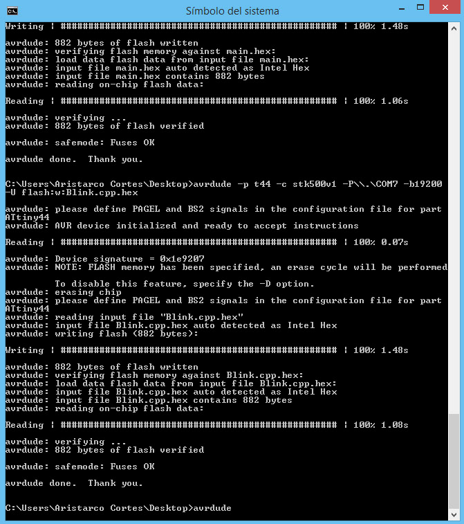
After our weekly meeting, thanks to Huber, a Fab Lab Puebla participant, we tried another way to program the board.
First step is to generate the .hex file with Arduino
Second, using the system simbol in windows we ran avrdude to program the board. It worked fine.