
Week 7 - embedded programming (Mar 11)
Assignment
This week's assignment was to read the ATtiny44A microcontroller datasheet and to programme the modified Hello Echo board we made during the previous week using the FabISP programmer. A stretch goal was to redesign the Fabduino board in Eagle and make it.
ATtiny44A microcontroller datasheet
The datasheet is quite a daunting document all 286 pages of it. James Fletcher from last year's Fab Academy 2014 gave the Manchester students a useful overview of how to read a datasheet. I learnt that the ATtiny44A can hold 4000 instructions and the clock speed dictates battery life (if running on battery). Using the 8 bit and 16 bit timers gives different levels of resolution 8 bit - 256 intervals, 16 bit 64,000 intervals. The universal serial interfaces (USI) has different protocols to talk to other devices including a computer, these include SPI, 12C and iwire but not RS232.
The summary page at front of the data sheet gives an overview of the features of the device.

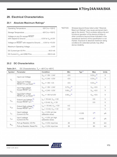
Section 20 - Electrical Characteristics on page 173 are important when designing circuits to ensure the maximum ratings are not exceeded which could damage the device. Also the feature parameters which should be taken into account when designing more complex circuits.
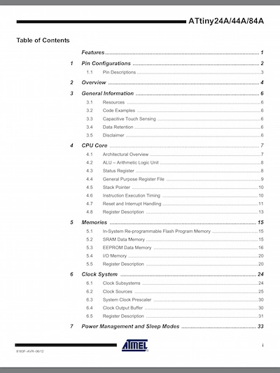
The table of contents starting on page 281 are useful to navigate the document.
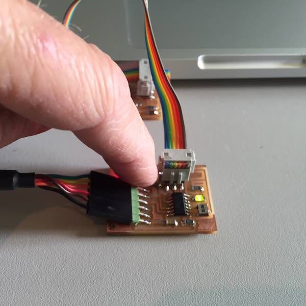
Programming the Hello Echo Button+LED board
This week has been a challenge without my MacBookPro which has been in for repair for a second time to replace the main logic board. So I used one of the Ellesmere Port FabLab latops and tried to get to grips with using Windows. I've done some programming a long time ago (35 years) so I set my sights on using the Arduino IDE to make the LED and button do something straightforward if not life changing.
I followed Anna Kaziunas France's tutorial on embedded programming to set up the USBtiny and FTDI drivers as well as getting the Arduino IDE to recognise the ATtiny44A programmer.
Initially I made some schoolboy errors. Firstly not connecting the ribbon cable correctly from the FabISP to the Hello Echo board, only connecting half the jumper pins (I blame my presbyopia). Also not setting the programmer to USBtinyISP in the Arduino sketch.
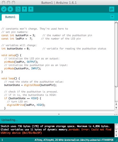
I then had to do some fault finding as I was getting an error uploading the Arduino sketches. My first sketch was a simple button press to turn on the LED. I followed the code from the Arduino button tutorial and modified it as I was using the internal pullup resitor on the device.
I found it confusing using the internal pullup resistor as using INPUTP_PULLUP for the pinMode() reverses the behaviour, HIGH means the LED is off and LOW means the LED is on. The digital pins tutorial explains this.
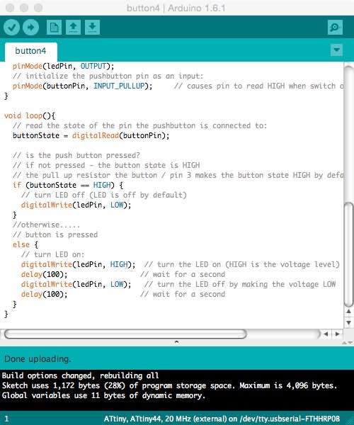
Success! The LED came on with the button press (button3 sketch) I then modified the sketch (button4) to make the LED flash.
Arduino sketch's for button3 and button4:
Tip from Michael the tutor Onformative has an HTML code formatter for Arduino/Processing.
arduino codebutton3
02
03
04
05
06
07
08
09
10
11
12
13
14
15
16
17
18
19
20
21
22
23
24
25
26
27
28
29
30
31
32
33
34
35
36
37
38
39
40
41
42
43
44
45
46
47
48
49
50
51
52
53
54
55
56
 /*
 LED On When Button Pressed

 Switches on a light emitting diode(LED) connected to digital
 pin 7, when pressing a pushbutton attached to pin 3.


 The circuit:
 * LED attached from pin 7 to ground
 * pushbutton attached to pin 3 from +5V
 * internal pullup resistor pulls pin 3 and the button to HIGH by default

 created 2005
 by DojoDave
 modified 30 Aug 2011
 by Tom Igoe
 modified for Hello Button + LED Board - 19 Mar 2012
 by Anna Kaziunas France
 modified to use internal pullup resistor - 17 Mar 2015
 by Philip Hemsted

 */

// constants won't change.
// They're used here to set pin numbers:
const int buttonPin = 3;     // the number of the pushbutton pin
const int ledPin =  7;      // the number of the LED pin

// initialize variables:
int buttonState = 0;         // variable for reading the pushbutton status

void setup() {
  // initialize the LED pin as an output:
  pinMode(ledPin, OUTPUT);
  // initialize the pushbutton pin as an input:
  pinMode(buttonPin, INPUT_PULLUP);     // causes pin to read HIGH when switch open and LOW when pressed
}

void loop(){
  // read the state of the pin the pushbutton is connected to:
  buttonState = digitalRead(buttonPin);

  // is the push button pressed?
  // if not pressed - the button state is HIGH
  // the pull up resistor the button / pin 3 makes the button state HIGH by default.
  if (buttonState == HIGH) {
    // turn LED off (LED is off by default)
    digitalWrite(ledPin, LOW);
  }
  //otherwise.....
  // button is pressed
  else {
    // turn LED on:
    digitalWrite(ledPin, HIGH);
  }
}
My second sketch was to make the LED flash when the push button was pressed. This was done using a delay with the digitalWrite command
arduino codebutton4
02
03
04
05
06
07
08
09
10
11
12
13
14
15
16
17
18
19
20
21
22
23
24
25
26
27
28
29
30
31
32
33
34
35
36
37
38
39
40
41
42
43
44
45
46
47
48
49
50
51
52
53
54
55
56
57
58
59
 /*
 LED Off Until Button Pressed

 Blinks a light emitting diode(LED) connected to digital
 pin 7, when pressing a pushbutton attached to pin 3.


 The circuit:
 * LED attached from pin 7 to ground
 * pushbutton attached to pin 3 from +5V
 * internal pullup resistor pulls pin 3 and the button to HIGH by default

 created 2005
 by DojoDave
 modified 30 Aug 2011
 by Tom Igoe
 modified for Hello Button + LED Board - 19 Mar 2012
 by Anna Kaziunas France
 modified to use internal pullup resistor and flashing LED - 17 Mar 2015
 by Philip Hemsted

 */

// constants won't change.
// They're used here to set pin numbers:
const int buttonPin = 3;     // the number of the pushbutton pin
const int ledPin =  7;      // the number of the LED pin

// initialize variables:
int buttonState = 0;         // variable for reading the pushbutton status

void setup() {
  // initialize the LED pin as an output:
  pinMode(ledPin, OUTPUT);
  // initialize the pushbutton pin as an input:
  pinMode(buttonPin, INPUT_PULLUP);     // causes pin to read HIGH when switch open and LOW when pressed
}

void loop(){
  // read the state of the pin the pushbutton is connected to:
  buttonState = digitalRead(buttonPin);

  // is the push button pressed?
  // if not pressed - the button state is HIGH
  // the pull up resistor the button / pin 3 makes the button state HIGH by default.
  if (buttonState == HIGH) {
    // turn LED off (LED is off by default)
    digitalWrite(ledPin, LOW);
  }
  //otherwise.....
  // button is pressed
  else {
    // turn LED on:
    digitalWrite(ledPin, HIGH);  // turn the LED on (HIGH is the voltage level)
    delay(100);                 // wait for a second
    digitalWrite(ledPin, LOW);   // turn the LED off by making the voltage LOW
    delay(100);                 // wait for a second
  }
}
Update
Working towards my final project I wanted to make the button press once for on and the press the button again for off. I found that Marco Sanalitro had developed a sketch to do this and I modified it as my hello world board used the internal pullup resistor on the ATtiny44.
arduino codebutton_on_off
02
03
04
05
06
07
08
09
10
11
12
13
14
15
16
17
18
19
20
21
22
23
24
25
26
27
28
29
30
31
32
33
34
35
36
37
38
39
40
41
42
43
44
45
46
47
/*
  Button turn on turn off

  Button press turns LED on and another button press turns LED off.

  The circuit:
 * LED attached from pin 7 to ground
 * pushbutton attached to pin 3 from +5V
 * use internal pullup resistor (use INPUT_PULLUP)

  by Marco Sanalitro
  March 2015

  modified 14 May 2015
  by Philip Hemsted

 */

int pinLed = 7;           // the number of the red LED pin
int buttonPin = 3;        // the number of the pushbutton pin
int ledState = 0;         // variable for reading the LED status
int buttonState = 0;      // variable for reading the pushbutton status
int oldButtonState = 0;   // variable memory of the pushbutton old status


void setup() {
  pinMode(pinLed, OUTPUT);           // initialise the LED pin as an output
  pinMode(buttonPin, INPUT_PULLUP);  // initialise the pushbutton pin as an input

}

void loop() {
  int buttonState = digitalRead(buttonPin);  // read the state of the pushbutton value

  if (buttonState == 0 && oldButtonState == 1){  // debouncing use the pushbutton status
     ledState = !ledState;                       // and a small delay
     delay (20);
     }

  oldButtonState = buttonState;   // give memory of pushbutton status
  if (ledState == 1){
     digitalWrite( pinLed, 1);   // turn red LED on
     }
  else {
     digitalWrite( pinLed, 0);   // turn red LED off
     }
}
Downloadable design files
Arduino Button1.ino
Arduino Button2.ino
Arduino Button3.ino
Arduino Button4.ino
Arduino Button_on_off.ino