Week 4 - electronics production (Feb 18)
Making a FabISP
This weeks task was to make a FabISP.
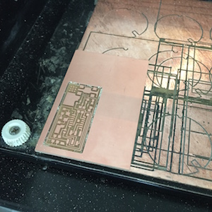
The first stage was to mill the circuit board out of FR1 (copper/phenolic paper laminate) PCB sheet using the Modella MDX-20.
Milling the board
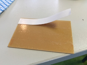
- Clean the sacrificial bed to remove old tape/adhesive. Use nail polish remover/cloth and paint scraper to scrape surface clean. The surface should be shiny and free from adhesive which might cause the board not to lay flat.
- Put double sided tape on the bottom of the sheet. Make sure there are no overlaps or bubbles on the tape, which might cause the board not to lay flat. Peel off the waxy backing of the tape, again make sure the corners don’t turn up and press back down if they do.
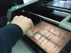
- Align and place sheet on the bed parallel to the x-axis and use felt pad to press sheet down firmly on the bed.
- Load Fab Modules from Ubuntu terminal.
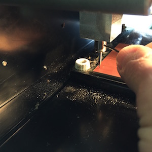
- Insert the 1/64" end mill tool into the chuck covering the shank and gently tighten the grub screw. Set the x-y origin using the settings in Fab Modules. Lower the tool towards the board using the down button on the Modella, leaving enough travel in the vertical axis to allow for milling depth. Loosen the grub screw and with finger on the side of the tool lower tool to the copper surface. Tighten grub screw firmly by applying a slight downward pressure on the tool with fingers to ensure the tool doesn’t move when the grub screw is tightened. Rotate chuck through three clicks and tighten other grub screw.
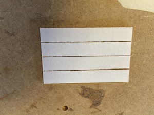
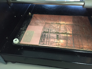
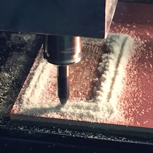
- Load the hello.ISP.44.traces.png from the FabISP files, selected mill traces (1/64) from the dropdown menu, made path and then made rml and sent to start the milling. At the start make sure the end mill is cutting through the copper layer successfully, which it was and let the job complete which took 13 minutes.
- Press the view button to get a good view of the board and to change the tool to a 1/32” end mill for cutting out the board. Clear away the cut material using a dust buster or blowing.
- Change the 1/64” tool to 1/32” end mill tool, but loosing the grub screw and repeating steps for 1/64” tool.
- Load hello.ISP.44.interior.png from FabISP files, select cut out board (1/32) from the drop down menu, made path and then made rml and sent to start milling. At the start make sure the end mill is cutting through the copper layer successfully, which it was and let the job complete which took 2 minutes.
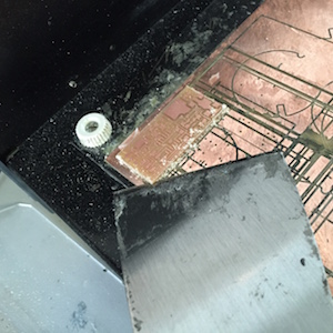
- After the board was cut out, used the scraper to prise the board and rest of sheet off the bed.
- De-burred the board with a small metal rule and washed under the tap using a sponge to clean and get rid of any dust/residue.
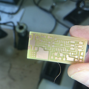
Stuffing the board
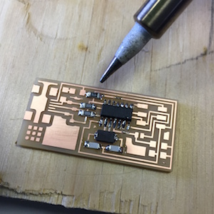
The next stage is to stuff the board with components.
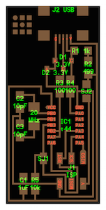
- Use hello.ISP.png as a reference to identify components and their position on the board.
- Use a soldering iron, tweezers and a magnifying glass with lamp to stuff the circuit board. I found this a challenge to master (perhaps my eyesight and too many cups of coffee beforehand were contributing factors). At one point I soldered the 499 ohm resistor onto the wrong pads and had to use a solder sucker to remove the solder and then reposition the resistor.
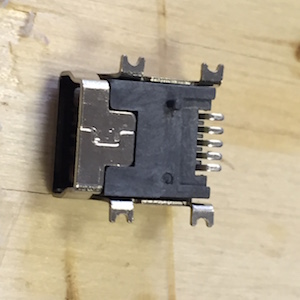
- The mini USB connector was particularly challenging to solder. The lower casing and spigots were removed to make it to solder the connectors. I had a number of attempts and soldering the connectors individually and ended up with solder bridging the gaps. I then used the copper braid to remove the excess solder and clear the gaps (or so I thought!). I checked for short circuits using a multimeter and found a short circuit, inspection using a magnifying glass revealed solder connecting two tracks. More use of heating braid on the excess solder appear to remove the problem.
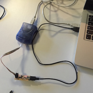
- The next step was to program the FabISP to be a programmer and followed the tutorial steps here. Having installed the software for the AVR programming.
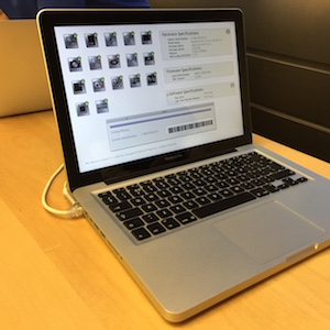
- I then did a ‘smoke test’ of the FabISP by plugging it into a USB port on the computer.
- DISASTER The screen went blank and the MacBookPro would not restart. This resulted in a trip to the Genius Bar at a local Apple Store, they managed to get the MBP working again by resetting the System Management Controller (SMC). I assumed there was still a problem with the FabISP board.
- The board was checked again by fellow student David Mason who found a short circuit under the USB connector and removed the excess solder.
- I redid the ‘smoke test’ on a Windows computer and this time it recognised the USB port.
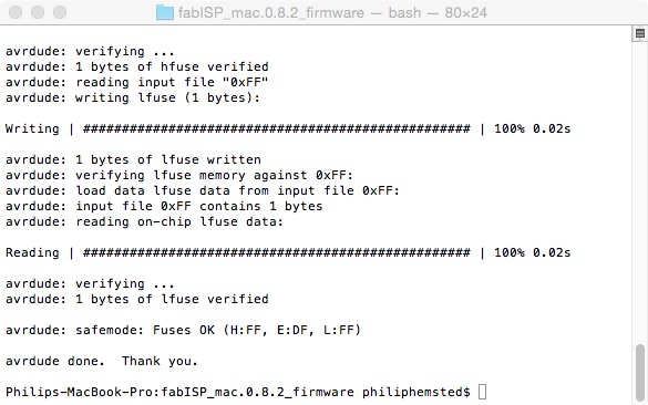
- The next step was to program the FabISP using the AVR programmer. Connecting the FabISP to the AVR and to the MacBookPro. The green light came on the AVR so no problems. I then used terminal to load the firmware on onto the FabISP and this loaded successfully.
- I then removed the 0 ohm resistor and solder bridge on the board to make it ready for programming.
- I then verified the FabISP was working correctly and plugged back into a USB port on the MacBookPro and the screen went blank and would not switch on again. Another trip to the Genius Bar.
- It turned out that was a fault on one of the two USB ports which caused the SMC to shut the computer down. A replacement main logic board was ordered and awaiting fitting.
Tip To reset the SMC on a MacBookPro mid-2012 and save a trip to the Genius Bar - press the (left side) Shift-Control-Option keys and the power button at the same time. Release all the keys and the power button at the same time. Press the power button to turn on the computer.