
Week 9 - mo(u)lding and casting (Mar 25)
Assignment
This weeks task was to design a 3D mould, machine it and cast parts from it. There are a number of steps in this process, firstly design a 3D part capable of being milled in XYZ planes and not just in 2.5D (as specified by Neil). Secondly mill a positive copy of the part out of machinable wax. Thirdly cast a negative flexible mould using silicon rubber. Finally cast the object in the silicon rubber mould using plaster or plastic.
Design
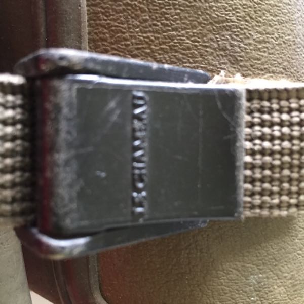
I'd had a part in mind for this week's assignment. A while ago I'd lost the clip from one of the straps on a wellington boot and I thought this would be a good test for my developing design skills as well learning about moulding and casting.
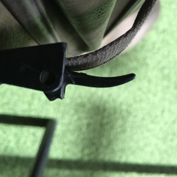
I set about by taking a picture of the clip on the other boot and made a vector of the profile in Inkscape.
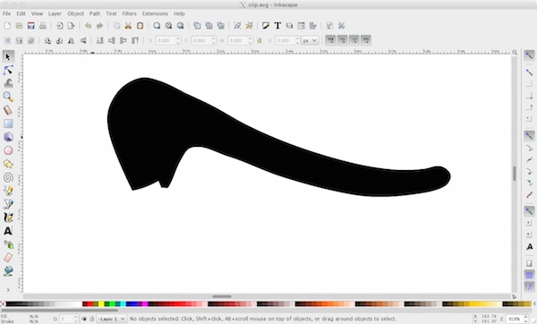
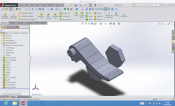
I then imported the shape into SolidWorks and designed the 3D part, by extruding bosses and mirroring to get a symmetrical part.

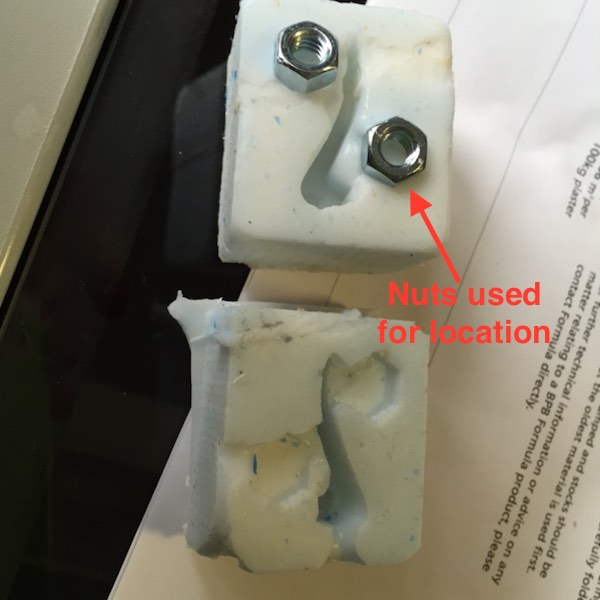
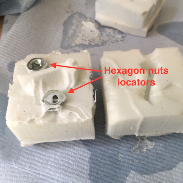
As the shape was did not have a flat plane that would enable a one-piece mould. I would have to split the part and make a two-piece mould. One immediate consideration was how to align parts. After one blind alley I thought of using hexagonal nuts as locators to ensure alignment of the two parts of the mould. The reason being the nuts were readily available and could be measured and modeled easily in SolidWorks.
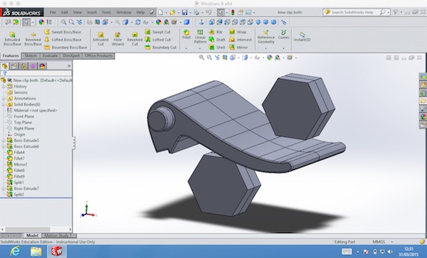
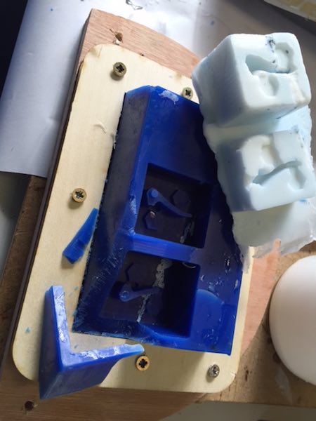
I split the part into two on the front plane and created two separate parts. On one of the side parts I added a gate and vent for casting. As the part is small 10mmx30mm there was not a lot of room to add them to the part.
I exported the parts as STL files from SolidWorks in order to make the toolpaths using PartWorks3D.
Toolpath
I loaded the STL files into PartWorks3D to configure the toolpaths.
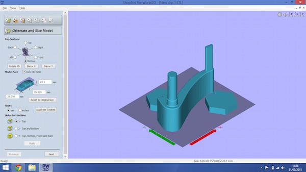
There are a number of steps in PartWorks3D to generate the toolspaths and are straightforward. Although I forgot to apply changes when selecting origin and updating dimensions which caused subsequent problems when milling not in the start position I intended.
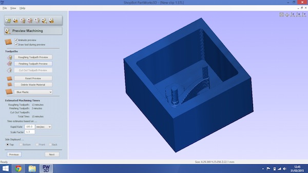
I chose to use a 0.125 inch flat end mill rather than a ball nose as I was not milling concave surfaces and the flat end would give a better finish on the bottom of the mould. The toolpath times for roughing was 13 minutes and 3 minutes for finishing (for one half of the clip).
Milling
Michael our tutor recommended using the ShopBot for milling the part rather than the Modella as it would be quicker and the Modella computer was being upgraded. I was interested to see if a small part could be milled with the ShopBot.
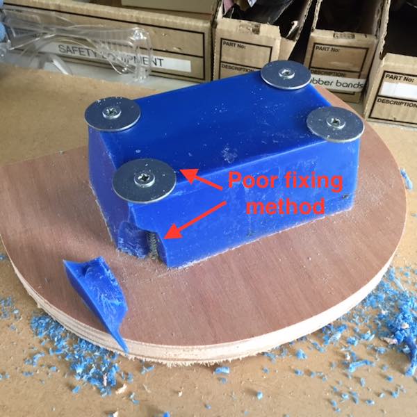
After using the ShopBot last week for milling plywood, I didn't use the plastic skirt and extractor fan in order to recycle the wax swarf. The machine wax block had to be secured to the bed of the ShopBot securely. My first attempt at fixing the wax wasn't too clever as the wax block broke at the corner and I reduced the size of the milling area with the washers to spread the load.
I used the same mill for both the roughing and finishing cut an 1/8" up-cut end-mill with the following cutting parameters, feeds and speeds:
Roughing toolpath
- Pass depth 0.0625 inches
- Stepover 0.05 inches 40%
- Spindle speed 12000 rpm
- Feed rate 1.6 inches/sec
- Plunge rate 1.0 inches/sec
Finishing toolpath
- Stepover 0.0187 inches 15%
- Spindle speed 12000 rpm
- Feed rate 1.6 inches/sec
- Plunge rate 1.0 inches/sec
Milling the first part seemed to go OK, but I realised I could only fit one of the sides on the block and would have to reverse the block to cut the other side of the part. This meant I couldn't make both sides of the flexible mould at the same time as they were on opposite sides of the block!
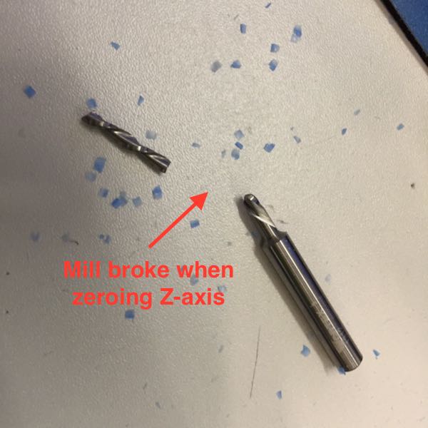
When I turned over the wax block to mill the other face I zeroed the X and Y axes using the the ShopBot manual controls and set up the Z axis using the automatic process with the spacer and crocodile clip. I'm not sure what happened as the mill moved along the Y-axis and not up the Z-axis. The top of the wax block was slightly concave (originally the bottom) the spacer dug into the wax, despite hitting the pause button the mill bit deflected and broke.
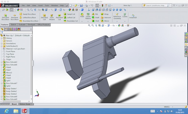
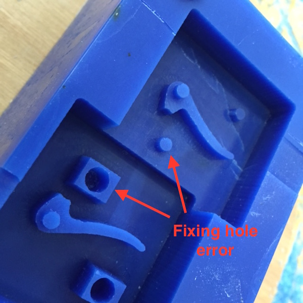
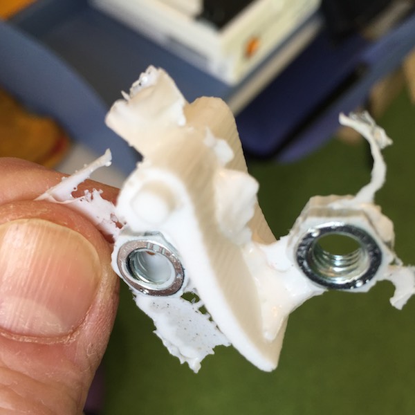
After milling both sides of the part on the same side. I realised I'd made a basic error in the design of the locating pin/hole. They were both on the same place so would not mate when negative flexible moulds were put together. I did a quick redesign using the hexagonal nuts for locators.
It was time to melt the wax and reform it into a clean block, I pack the voids with wax chips and set the oven to 140℃. The wax melted in under 30 minutes, but still had solid lumps in the bottom after checking with a wooden spatula. A further 10 minutes and the wax was fully melted and left the tin to cool outside of the oven.
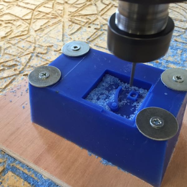
After the wax block had solidified and released from the tin. I remounted on a jig to give a larger milling area on the top surface.
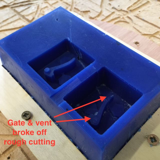
I hit another problem in milling the parts. This time the gate and vent broke off in the rough cutting. Due to their small diameters.
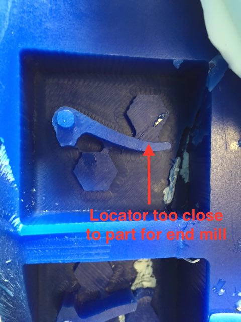
On inspecting the mould I found another error. The hexagonal locators were too close to the side of the part and the toolpaths hadn't had a cut through. Although I'd previewed the toolpaths in PartWorks3D I didn't spot this.
Moulding
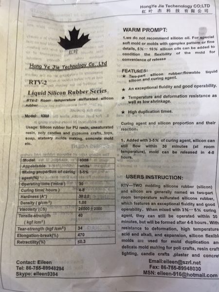
Despite the mould being broken I decided to mak a flexible mould using RTV-2 silicon rubber using 4% curing agent to liquid silicon by weight.
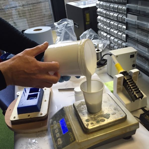
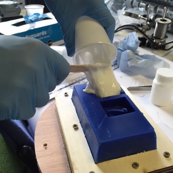
After mixing the liquid silicon and curing agent with a wooden spatula using a shearing action rather than folding to minimize air bubbles for 3 minutes. I poured the silicon rubber into the mould. Having a small void space around the part does not make it easy to pour the rubber aroung the part, a larger void would have been better.
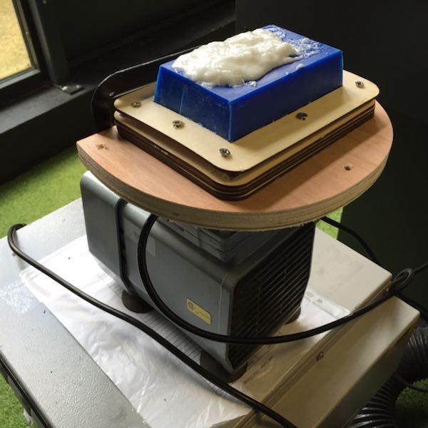
I tried using the vibrations of the laser cutter vacuum pump to remove bubbles in the silicon rubber before it cured.
After curing for a couple of hours I removed the silicon rubber from the mould and the mould cracked in the process. As expected the quality of the flexible mould was disappointing.
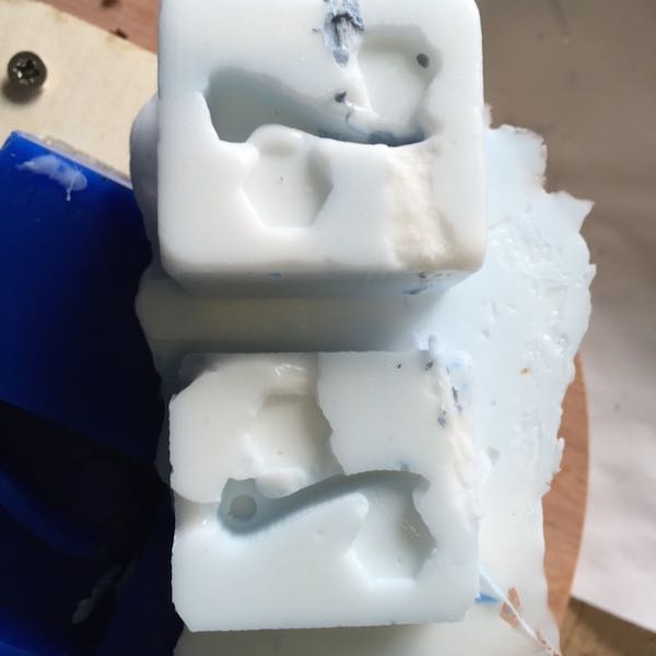
At least the hexagonal nuts worked as locators.
Second attempt
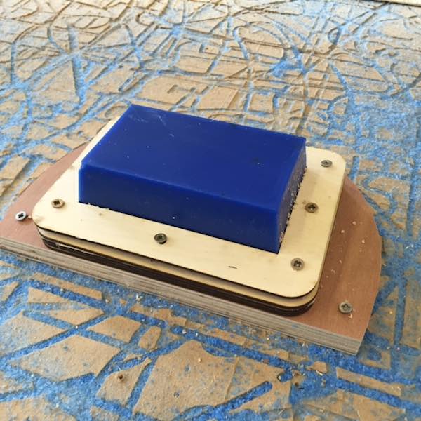
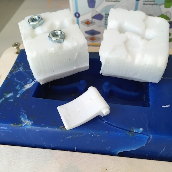
Having learnt from my first attempt and mould making. I redesigned the part placing the locators further away and made both parts in the same void and removed the gate and vents as they were likely to break and would add them later.
The larger void space made it slightly easier to pour in the silicon rubber although I could not see whether the parts were fully covered or not.
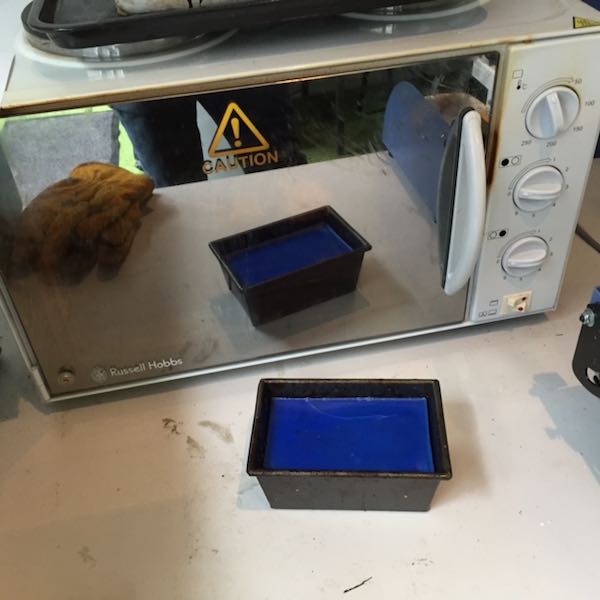
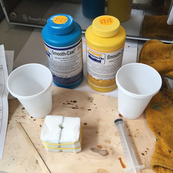
I decided to cast the part using Smooth-Cast 310 liquid plastic as it has ultra low viscosity (useful for pouring into a small mould), 15 minute pot life and 3-4 hour cure time . The plastic is made from two parts - Part A and Part B. Part A is harmful so safety goggles, gloves and adequate ventilation are required.
Steps in using the liquid plastic compound:
- Combine equal amounts of liqud parts A and B
- Mix liquid plastic thorougly
- Pour into rubber mould and top up if air bubbles appear
- Wait 3-4 hours for plastic to cure
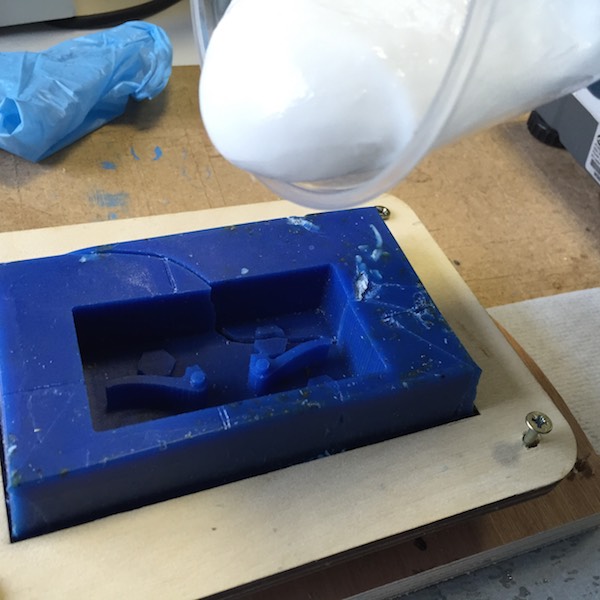
Once mixed the liquid plastic was easy to pour and stayed colourless for 20 minutes, I even thought I hadn't mixed the right parts together as I expected it to go white almost immediatedly. I squeezed the moulds to encourage air bubbles to rise and topped up the gate in the mould, which I'd cut manually with a safety knife. The parts of the mould were securley held together with elastic bands.
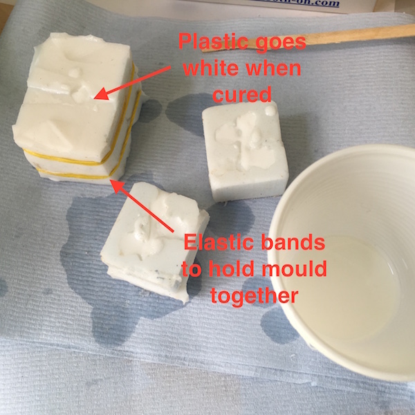
After an hour I split the mould apart and found that the plastic had cured
Looking at the part there was quite a lot of flash on the mould boundary and where the silicon rubber hadn't fully flowed into.
Finally I removed the flash with a safety knife. Overall I was quite pleased with the end result, considering the problems I had with milling the machinable wax mould. The liquid plastic was a lot easier to work with than the silicon rubber.
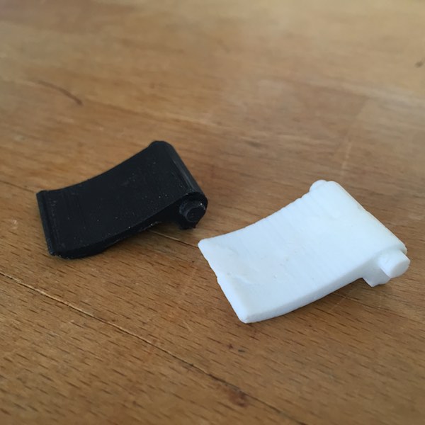
Here's a comparison between the cast part in white and 3D printed part in black. The cast part feels more robust as it is solid, whereas the 3D printed part has a lattice internal structure.
Lessons learnt
I made quite a few mistakes this week and brought the adage "more haste, less speed" to mind. Among the lessons I learnt this week are:
- Make the void space around the part large enough to pour into with silicon rubber.
- Don't neglect the mould design as well as part design as this can impact on the quality of the flexible mould.
- Always double check PartWorks3D and ShopBot options before milling, and press the Appply button for changes to take effect in PartWorks 3D.
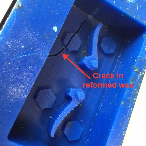
- Examine wax blocks for surface cracks as they will likely go through the block.
- Be patient and don't rush cooling, mixing and curing times.
- A benefit of soft moulding is being able to remove the part easily and be able to reuse the mould.
Files for download
The files from this week's assignment can be downloaded from a Dropbox folder by clicking on the following link.
Downloadable design files
Solidworks Another clip.SLDPRT
Another clip.STL
clip 1.SLDPRT
Inkscape clip.svg
Solidworks New clip assembly.SLDASM
Solidworks New clip both.SLDPRT