
Week 6 - electronics design (Mar 4)
This weeks assignment was to redraw the Hello Echo board adding a push button and an LED.
Having no previous experience of electronics design I decided to use Eagle the electronic design automation tool with its extensive tutorials and component libraries. As well as using the Eagle tutorials I watched a series of videos on Eagle tutorials by Jeremy Blum and followed Anna Kaziunas France's intro to Eagle .
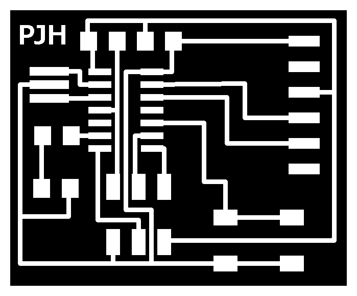
The schematic and board designs are shown below.
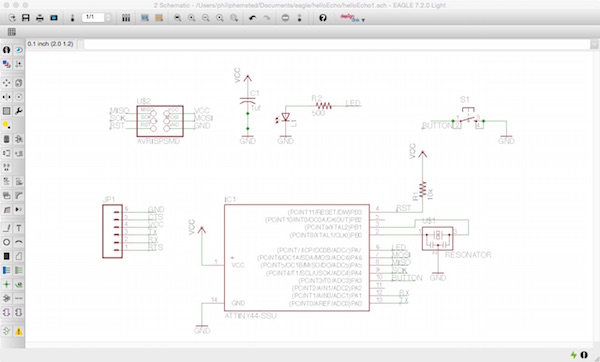
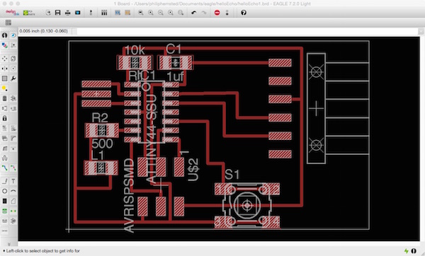
The Eagle schematic and board design files can be downloaded here
The Eagle tool has commands to check circuit board designs for errors, electrical rules and design rules. This proved a useful in identifying errors which could be ignored or needed attention. The error below is because there is not the minimum amount of clearance between the pads for the push button switch and the edge of the board, set at 16mil or 1/64 milling tool width.
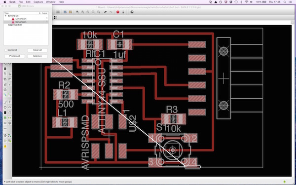
I ignored this error as the traces were exported as a png to GIMP and a border of 20px was added to the canvas size.
I used fabmodules to check all the traces were being cut and spotted a problem with the three traces under the IC.
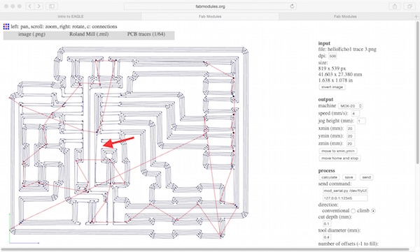
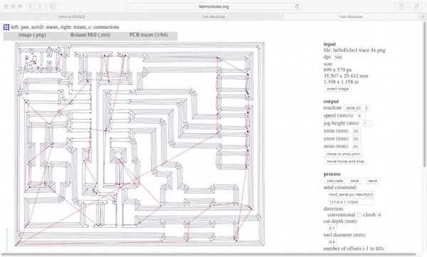
Although the Eagle Design Rules Check didn't raise an error a mill trace had been missed off between the bottom right IC pad and the nearest vertical trace. Having discussed this with the tutor a number of work arounds were proposed if fabmodules doesn't cut the copper:
- Use a scalpal to cut the copper after the board has been milled.
- Export the top traces image from Eagle at a higher resolution, originally used 500dpi, but would try 1000dpi.
- Move the trace to make more space between the pad and the trace.
- Remove small amount from the pad in GIMP to create a larger gap with the trace.
- Reduce the default tool diameter in fabmodules, to get it to think there is more space available for the tool path.
Out of the five alternatives, the higher resolution, editing in GIMP and spoofing the tool diameter worked. I opted to use the GIMP for editing the image as I found this the easiest to do/undo.
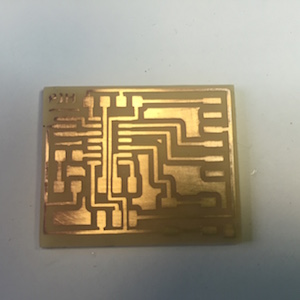
With the traces sorted out I saved a border image as well as the traces and milled them on the Modella.

Milling board on Modella
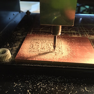
The finish on the milled board was not as good as in week 4, suggesting the milling tools had been blunted with use
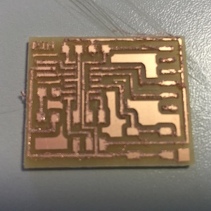
After cleaning and a light rubbing with emery paper, the board traces looked better and ready for stuffing.
It took a lot less time to stuff the hello echo board than the FabISP board in week 4.
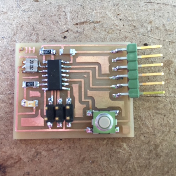
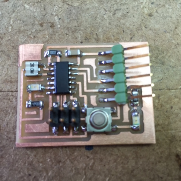
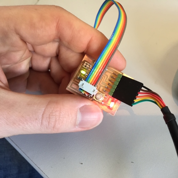
When I tested the board it would not burn the bootloder using the Arduino IDA. Further electrical testing and rechecking solder joints did not resolve the problem. So I decided to make another board adding a red LED to show the board was powered and this time the board could be programmed successfully.
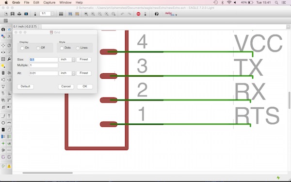
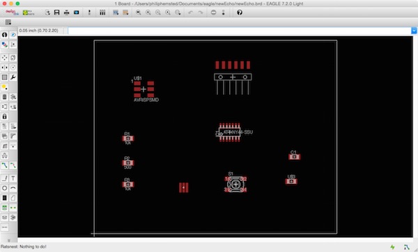
One lesson I learnt using Eagle is not to change the grid size. I attempted to redesign the hello echo board from scratch and drew the schematic with components in different positions and orientations from the original design. As a test I changed the Grid size from the default of 0.05 inch to 0.1 inch. When I started connecting components with the wire command I found it difficult to snap to components (but thought little of it) and when I used the Ratsnest command on the board layout a message appeared say 'Nothing to do!' implying that no wires were connected.
Design files for download
Eagle board helloEcho1.brd
Eagle schematic helloEcho1.sch
Eagle board newEcho.brd
Eagle schematic newEcho.sch