
Final project
Brief
To integrate the processes and skills learned on Fab Academy into a final project.
Concept
The initial project idea was to develop a wearble device to give a runner feedback on foot landing techniques and running form. This was of personal interest as I've tried to change my running style from heel striking to a midfoot landing style in order to reduce kneed and calf running injuries.
The final project idea changed after input and output devices weeks. I enjoyed making the Charlieplex LED array and the challenge of being able to change the display pattern with external sensor inputs was appealing.
So the final project idea morphed into an alert rear bike light. The light would be able to sense approaching vehicles and change pattern to alert drivers of the cyclist. Another function is to use the light as a wearable brake light in order to alert other cyclists behind of sudden braking.
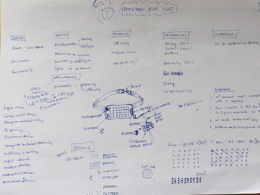
Using the spiral project development methodology I started by breaking down the concept into sub-systems, processes and a list of questions to be answered. This was put together in a project plan as detailed in week 16 - applications and implications
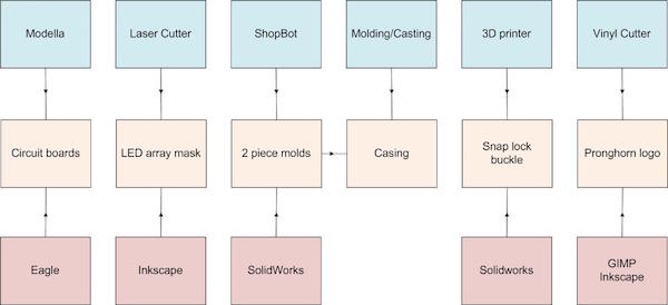
Fab manufacturing process
Charlieplexing v multiplexing
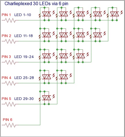
After the output devices week I thought it would be interesting to use a large array of LEDs for a rear bike light to alert car drivers. In the output devices week I made a 20 LED array controlled by 5 pins of an ATtiny44, this technique is known as Charlieplexing and was referenced in 2001 by Don Lancaster's tech musings.
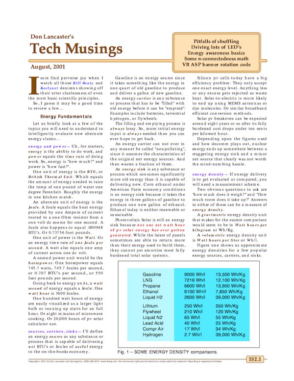
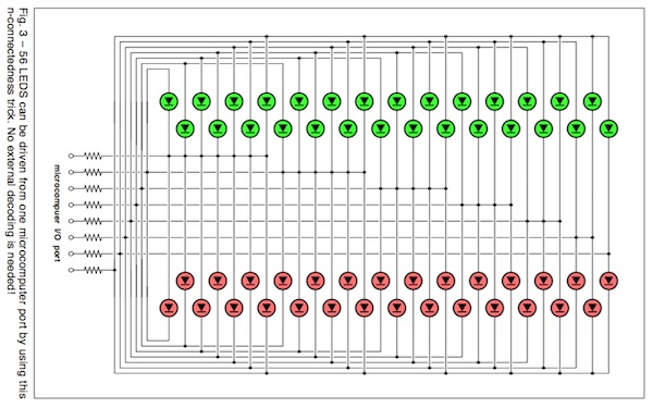
Before embarking on the Charlieplexing route I researched the differences between Charlieplexing and multiplexing. Multiplexing requires (N/2)2 pins compared to (N2-N) for Charliplexing, 6 I/O pins on a microcontroller can control 30 LEDs Charlieplexed whereas only 9 LEDs can be controlled by multiplexing. However controlling the brightness of a Charlieplexed array is an issue as each one is cycled individually, relying on persistance of vision to trick the eye into seeing the LED on when it is turning on an off very quickly.
As I was planning to use a number of input devices which would require I/O pins I decided to Charlieplex rather than multiplex the LED array.
Spiral project development
Mockups
Not being very proficient in 3D computer aided design I made a number of laser cardboard mockups of the bike light to get a feel for sizing and spacing of components. This helped me decide on the size and shape of the LED array as well as the pitch spacing of the LEDs.
 Downloadable design files at the bottom of the page
LEDs
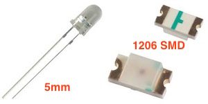
My original choice was to use 5mm LEDs as this would give a stud like effect in through the bike light casing. However I changed to 1206 SMD LEDs as will be explained later.
Measuring device
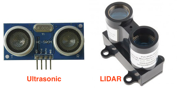
Another decision was the type of input device to detect an oncoming car approaching the cyclist. In the input device week Neil mentioned the HC-SR04 ultrasonic ranging module being lower cost than the indivudal components ($2.99 on eBay). The range of the HC-SR04 is 2cm-4m, which is not ideal for detecting an oncoming car travelling at 50 mph which travels 33m in 1.5 seconds (1.5 seconds is a ballpark car driver's detection/reaction time). After researching on the Internet I found a laser measuring device LIDAR-Lite laser module which had a range of up to 40m, but at a cost of $89.00. Given that the overall project budget should be $10's not $100's I chose to use the HC-SR04 which would prove the concept and allow for upgrading to the LIDAR device if the project was taken further.
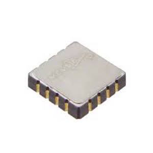
3D accelerometer
Another input device I was looking to use was a 3 axis accelerometer MXR9150G to be able to detect deceleration and changes in direction. LucidBrake already offers this type of functionality in their bike brake light. However I was concerned about the small packaging size of the component with 12 I/O pins and my ability to solder it onto the circuit board. One of the challenges of being over 50 years old is presbyopia and the difficulty in seeing small objects (even with the help of magnification). I decided not to include the accelerometer in the initial prototype as it was not a key differentiator to existing products.
I/O pins
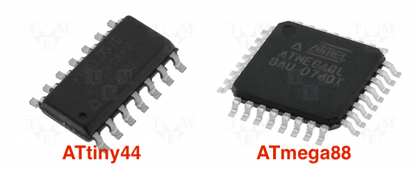
I calculated the number of I/O pins needed for the electronics design (this included the 3 axis accelerometer, ultrasonic distance detection, photodetector, button, 30 LED charlieplex array and programming) this came to 15 more than the 12 digital I/O pins available on the ATtiny44. This would mean using a ATmega88 IC MCU 8BIT 8KB FLASH 32TQFP. Again I was not confident in my ability to solder the quad flat package 32 pins. Having scaled back the number of input devices in the design I needed 10 I/O pins so could use the ATtiny44, which I had soldered successfully in the past.
Electronics design
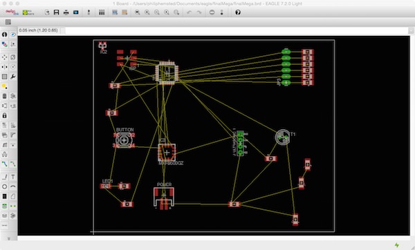
The free version of Eagle to desgin the electronic circuits limits the usable board area to 100x80mm, this was OK for the microcontroller and input device electronics, but not for the 30 LED array, which would be a 10 column x 3 row array, approximately 150mm wide. Before I reduced the number of input devices I started a design with the ATmega microcontroller and the input devices, but found routing the nets a real challenge and after an afternoon hadn't achieved anything like a completed design.
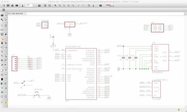
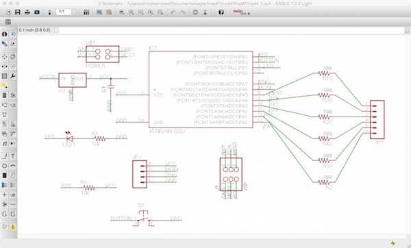
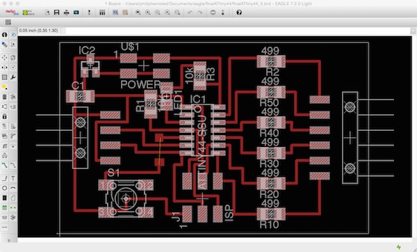
So I reset my goal on using the ATtiny44 with fewer input devices simplifiying the design. I was able to route the traces with one via. ALL DESIGN FILES ARE AVAILABLE TO DOWNLOAD AT THE BOTTOM OF THE PAGE.
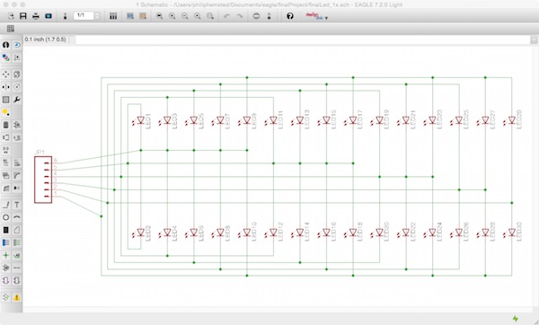
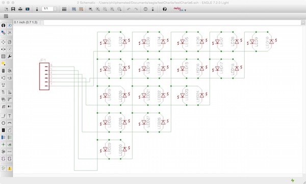
The next step of the electronics design was to design the 30 LED charlieplex array. I thought this was going to be an easier task than the microcontroller and input device board (how wrong could I be!).
I adapted the design from Don Lancaster's 56 LED array (see above) for 30 LEDs in the Eagle Schematic, but didn't use the Eagle Board layout as I wanted the array larger than the 100x80mm limit.
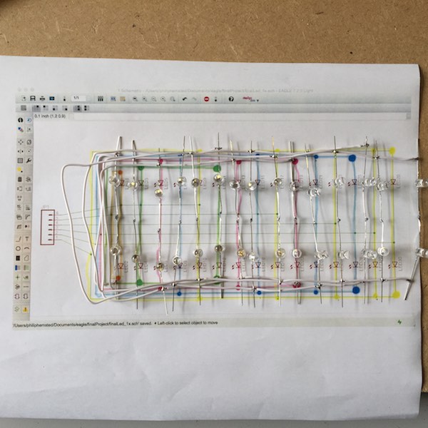
I used an image of the Eagle schematic in GIMP and the airbrush tool to highlight the sub-nets of the array and used this as a template when making the wire array (see later).
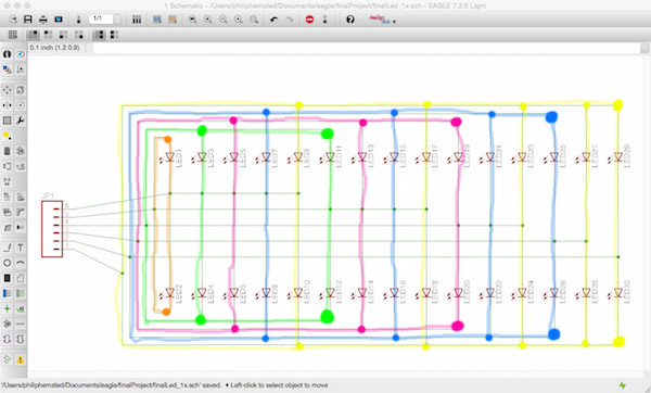
As a back-upup I modified the Eagle schematic from a 15x2 array, to a 10x3 array, to see if it was easier to make a wire array as a 10x3 array instead of the 15x2. This added some complexity to the pattern and I decided to stick with the 15x2 as I could see the connection pattern more easily.
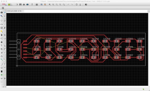
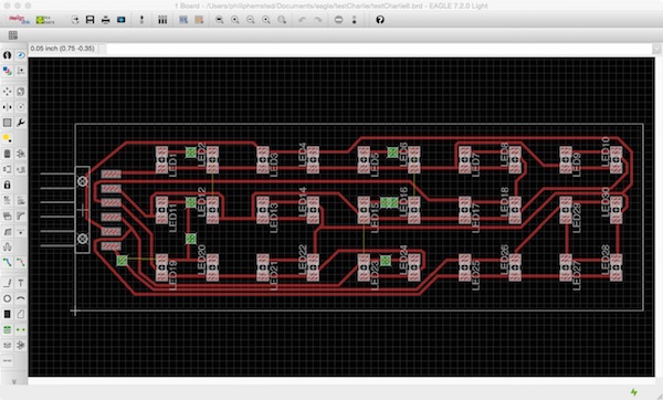
As another back-up I used the Eagle autorouter to make a 10x3 array with 1206 SMT LEDs on a 100mm wide board, this required 7 vias.
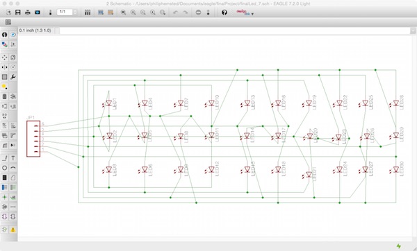
I kept on looking for a better solution for a 10x3 LED Charlieplex array, and came across an online tool for generating Charlieplex arrays here.
Designing the Eagle schematic was a straight forward task being able to see the logical pattern easily.
I used the Eagle autoroute function and then edited the nets to get make a circuit board with 4 via's instead of 7.
 Downloadable design files at the bottom of the page
Wiring LED array
My initial thought was to use a wires to connect Charlieplex 10x3 LED array and would then to investigate PCB and copper traces.
I thought it would be a relatively straight forward task of soldering together a wire loom using the Eagle schematic tempate, which I'd engraved and cut out of cardboard using the laser cutter.
I soon found that wiring short pieces of wire the heat dissapation melted the insulated cover.
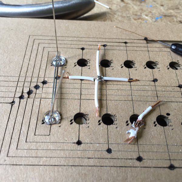
I had more success by using the wire stripper to remove the insulation mid wire and wrap wires together before soldering.
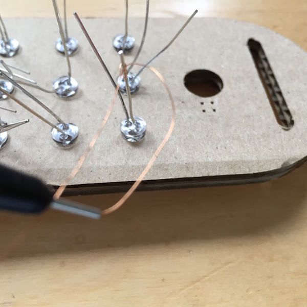
I then tried a different approach using a wiring pen, which uses thin copper with an inulating layer of varnish which burns off when soldered and makes a connection.
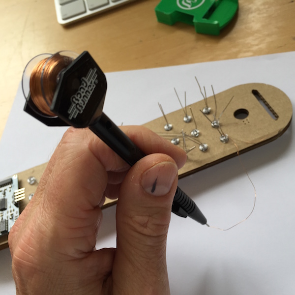
This approach wasn't successful as I kept on breaking the wire and needed another hand to solder and route at the same time.
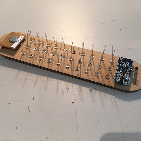
I eventually soldered a complete wire loom with 30 LEDs, following the 15x2 LED array pattern. It became apparent the opportunity for short circuits by using the bare legs of the 5mm LEDs.
The challenge was turing the 15x2 array into a 10x3 array without short circuits.
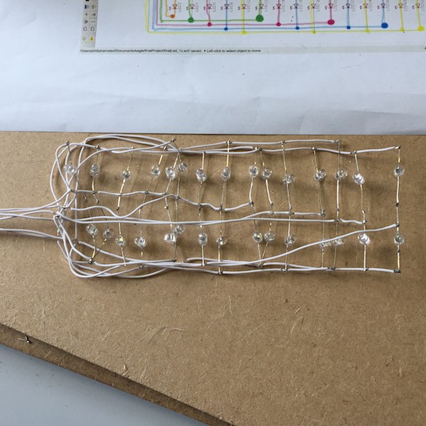
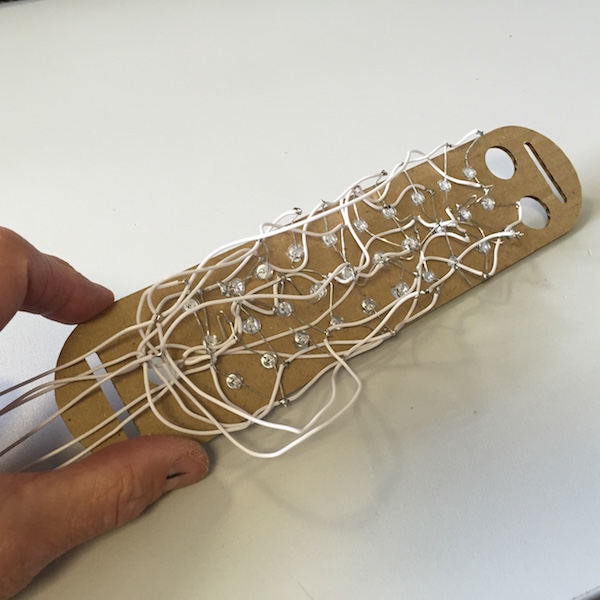
I used one of the cardboard mockups I'd made earlier as a template for the 10x3 array. The 4.9mm diameter holes in the carboard held the 5mm LEDs securely and I was able to maniulate the wires to make the 15x2 array fit the 10x3 array.
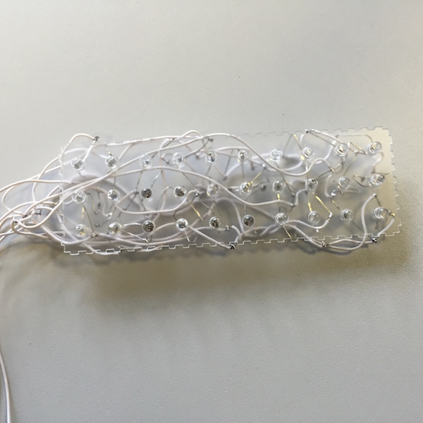
I laser cut a perspex LED array spacer as this would be better for encapsulation when making the silicon rubber casing .
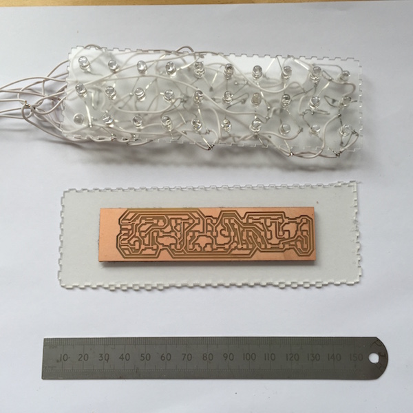
Here's a comparison of the 5mm LED wire array with the 1206 SMD LED circuit board array. The 5mm LED wire array is a better sized display to fit on a cyclist back.
Copper traces
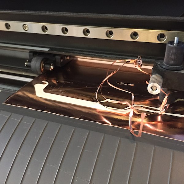
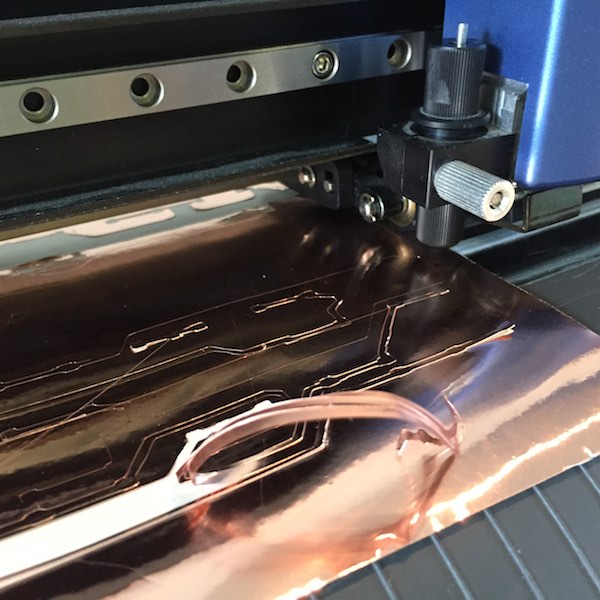
After feedback on the final project review I investigated copper traces for the array with the vinyl cutter and copper roll. The array could made larger than the PCB limit and also thinner, more robust than the wire loom and flexible.
Initially I used the default settings on the vinyl cutter of 20 cm/s and 90 gf. This produced a tangled mess of swarf!
Slowing the vinyl cutter speed down to 5 cm/s and reducing the knife pressure to 70 gf, produced better results but the copper traces were still lifting from the backing.
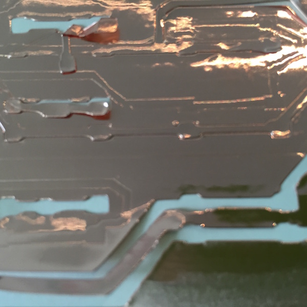
Even with doubling the width of the copper traces at the slower speed the long traces detatched from the backing sheet. I decided to stop this investigatation and to return to it later if time permitted.
Circuit board
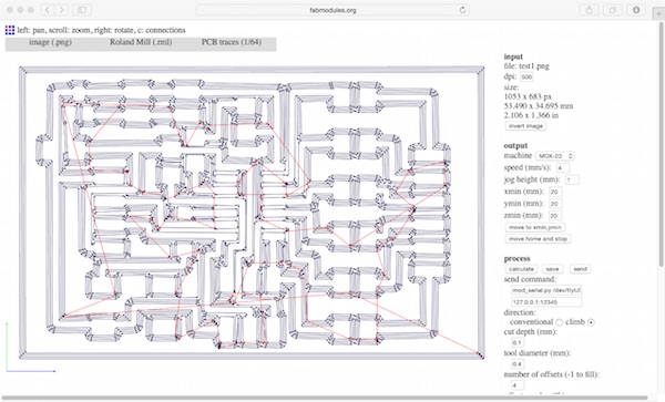
My first attempted at milling the board, had to have a second pass with a low spot on the bed in the bottom left hand corner.
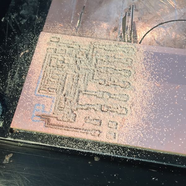
When I milled the outline with the 1/32" mill I forgot to increase the canvas size in GIMP and hadn't allowed enough clearance around the perimeter to clear the traces at the bottom of the board. Also using the 1/32" mill to make via holes cut through traces which would make soldering difficult.
When I redid the board I tweaked some of the traces with the move command and didn't spot a problem with the traces between the legs of the ATtiny44 until I had stuffed the board and found a short circuit when continiuty testing.
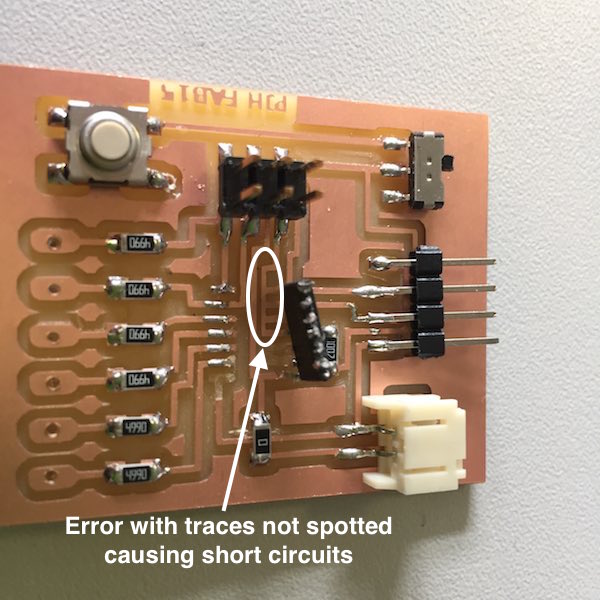
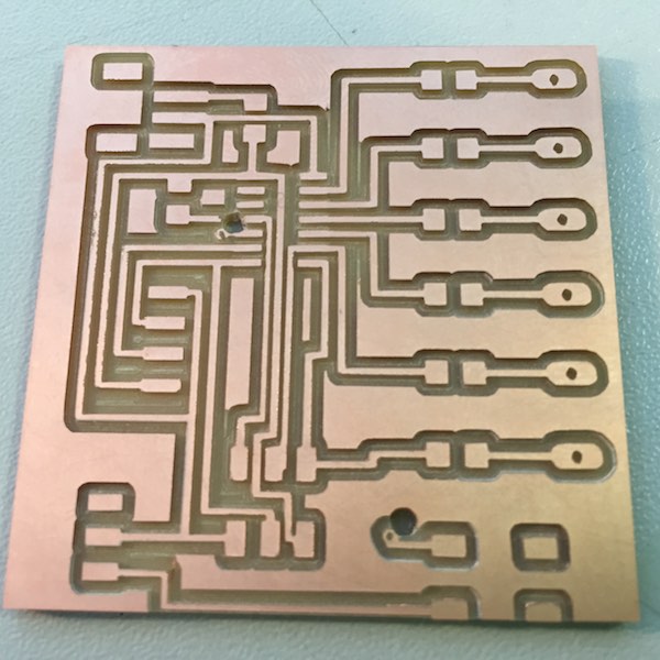
At the third attempt I made the circuit board sucessfully.
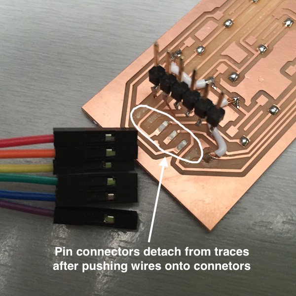
I also milled an array board, but while putting the connecting wires onto the board I managed to detatch the pads. This didn't happen in previous weeks! I remilled the board and changed the way I connected the wires to soldering straight onto the pads and using some hot glue on top to protect them.
 Downloadable design files at the bottom of the page
Testing
Having got a working circuit board and a 10x3 LED array I was now ready to do some testing. Oh dear - lot's of short circuits, instead of one LED lighting multiple LEDs were coming on at the same time.
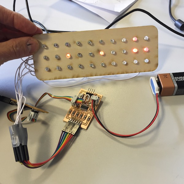
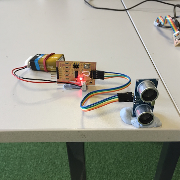
At least the ultrasonic distance measure was working.
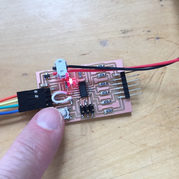
And the push button.
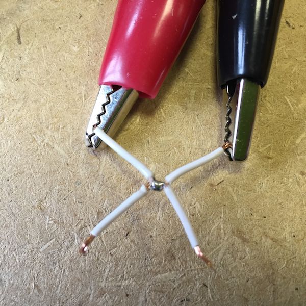
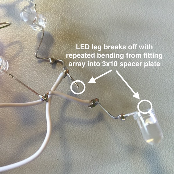
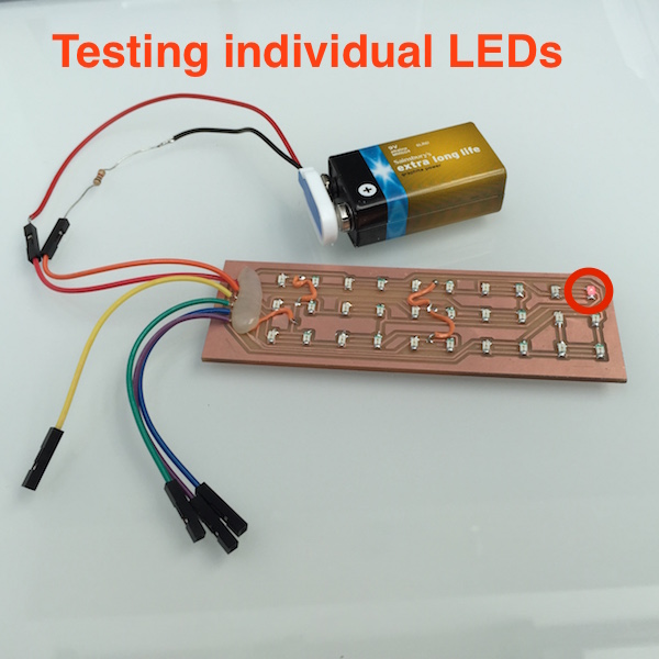
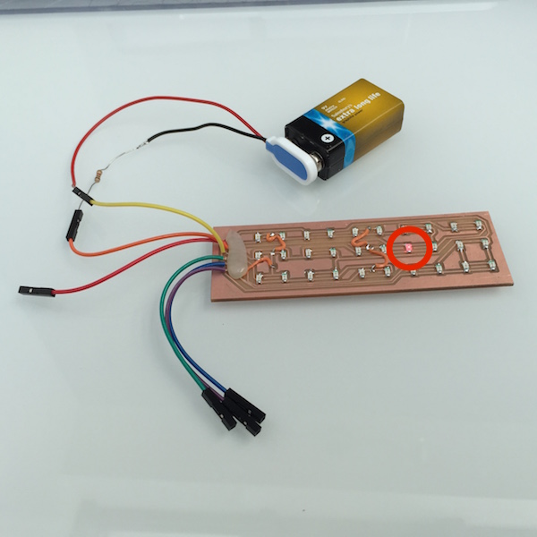
For the initial testing of the LED array I had been flashing the microcontroller with modified code to only flash one LED (by commenting out all other lines). This took a couple of minutes to repeat. An easier way was to use a battery and resistor and connect each wire in order. Again this highlighted problems of short circuits.
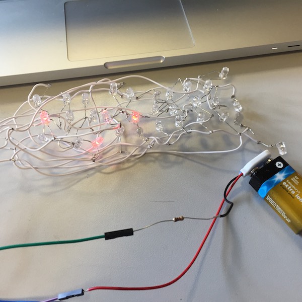
Placing and replacing the LED array resulted in one of the LED legs breaking and led me to abandon using 5mm LEDs and the wire array. Looking back it seems obvious that this approach was likely to fail.
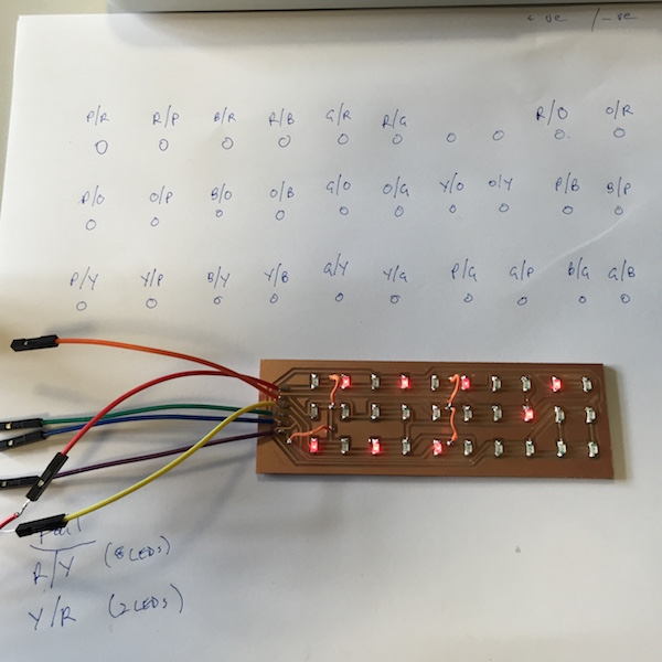
Back to the drawing board or the back-up circuit board. I'd rainbow colour coded the 6 connector wires (red, orange, yellow, green, blue, indigo) this made it easy to test the array by connecting the battery/resistor and recording which LED lit depending on the combination of two wires. All was going well until I hit a problem with 8 LED's coming on for the red and yellow wires . . . . aaaah!
Back to the magnifying glass and I'd soldered 3 of the LEDs the wrong way around.
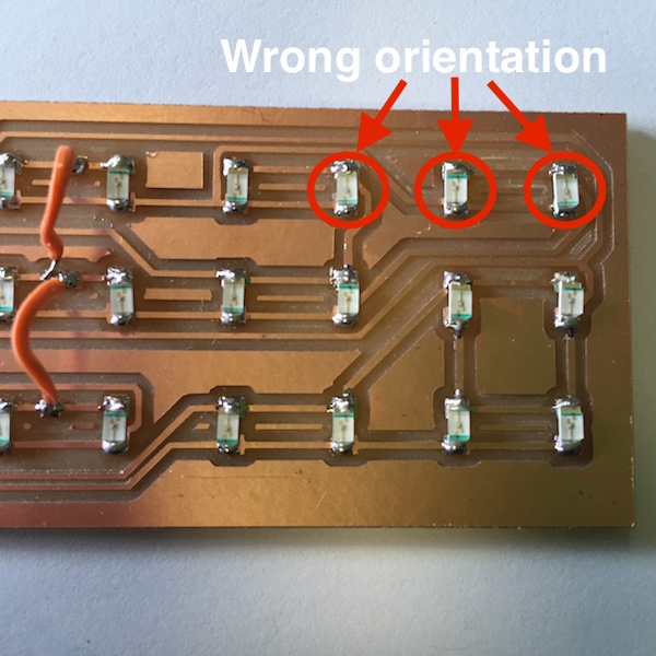
After desoldering the offending LEDs I resoldered them the correct way round and success the combination of pairs of all the wires would light each LED individually. . . . phew!
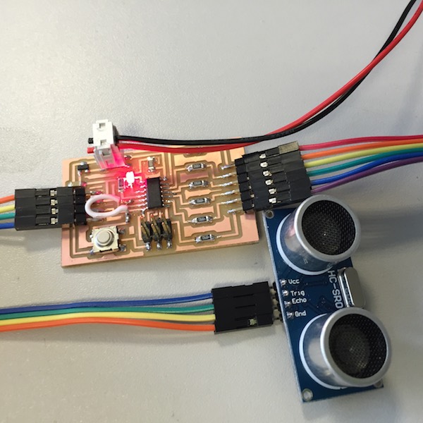
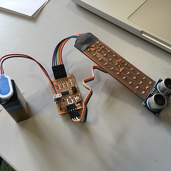
I was able to connect the boards together and start getting the input and output devices working together.
 Downloadable design files at the bottom of the page
Coding
Taking Neil's advice of reusing exisiting code, I started with the hello.array.44.c code I used in the output devices week.
With only a basic knowledge of programming I was guided by James Fletcher from Fab Academy 2014. I understood the program had to behave in a different way than for the output devices week as it used the HC-SR04 ultrasonice distance device to monitor if a large reflective object (car) came within a set distance of the bike light and to change the flashing pattern of the display.
In summary the main loop of the code runs in the following way.
- The HC-SR04 ultrasonic sensor generates a 1ms trigger pulse on the trigger pin.
- If an echo is detected on the echo pin after a set time delay the LED charlieplex array displays a chevron mode and cycles through different chevron patterns to make a moving display.
- If an echo is not detected on the echo pin the LED array displays the default bike light mode cycles through the LED array in columns, switching each LED on and off in turn.
- The main loop repeats.
Code snippet - mapping 3x10 LED array
During the testing of the LED charlieplex array a note was made of the combination of pins which turned each LED on in the 3x10 array, this was used to to define a constant for the led_mapping. Another constant was used to define the chevron patterns to display by using 1 to indicate the LED is on and 0 for off.
        // Mapping of the 3x10 LED array
        const uint8_t led_mapping[30][2] = {
        {A,F}, {F,A}, {B,F}, {F,B}, {C,F}, {F,C}, {D,F}, {F,D}, {E,F}, {F,E},
        {A,E}, {E,A}, {B,E}, {E,B}, {C,E}, {E,C}, {D,E}, {E,D}, {A,B}, {B,A},
        {A,D}, {D,A}, {B,D}, {D,B}, {C,D}, {D,C}, {A,C}, {C,A}, {B,C}, {C,B}
        };

        // Define chevron patterns using a constant array
        const uint8_t chevron_frame1[30] = {
        1,0,0,0,1,0,0,0,0,0,
        0,1,0,0,0,1,0,0,0,0,
        1,0,0,0,1,0,0,0,0,0
        };

        . . .

        void led_chevron_frame1(void) {
            uint8_t delay = 1;
            int i;

            for(i=0; i<30; i++) { // step through all leds in the display
                if(chevron_frame1[i] != 0) { // display led on
                flash(led_mapping[i][0], led_mapping[i][1], delay);
                }
            }
        }
Code snippet - light all LEDs
The defalut bike light mode cycles through the LED array by column.
        void led_frame_all_on(void) {
            // Light all LEDs
            uint8_t delay = 25;

            flash(A,F,delay);
            flash(A,E,delay);
            flash(A,D,delay);
            flash(F,A,delay);
            flash(E,A,delay);
            flash(D,A,delay);
            flash(B,F,delay);
            flash(B,E,delay);
            flash(B,D,delay);
            flash(F,B,delay);
            flash(E,B,delay);
            flash(D,B,delay);
            flash(C,F,delay);
            flash(C,E,delay);
            flash(C,D,delay);
            flash(F,C,delay);
            flash(E,C,delay);
            flash(D,C,delay);
            flash(D,F,delay);
            flash(D,E,delay);
            flash(A,C,delay);
            flash(F,D,delay);
            flash(E,D,delay);
            flash(C,A,delay);
            flash(E,F,delay);
            flash(A,B,delay);
            flash(B,C,delay);
            flash(F,E,delay);
            flash(B,A,delay);
            flash(C,B,delay);
        }
Code snippet - processing ultrasonic sensor
The ultrasonic sensor sends out a trigger pulse and if an echo is received on the echo pin is less time than the defined time (distance) in this case 10 milliseconds the LED array displays the chevron mode otherwise the default bike light mode is displayed.
       //
       // Process ultrasound sensor
       //

       // Generate a 1ms trigger pulse
       set(ultra_port, ultra_trig_pin); // trig pin HIGH
       _delay_ms(1);
       clear(ultra_port, ultra_trig_pin);

       // wait for echo to go high
       while(pin_test(ultra_pin_reg, ultra_echo_pin) == 0)
            ;

       // count how long echo remains high
       echo_time = 0;
       while(pin_test(ultra_pin_reg, ultra_echo_pin) != 0) {
           echo_time++;
           _delay_us(500);
       }
       //
       // time in milliseconds, speed sound 340 m/s, or 1 ms = 17cm for echo there & back
       //
       if(echo_time < 10 /*40*/) {
           set(ob_led_port, ob_led_pin); // led on
           led_mode = 1; // chevron mode
       } else {
           clear(ob_led_port, ob_led_pin); // led off
           led_mode = 0; // bike light mode
       }
Downloadable program file at the bottom of the page
Casing
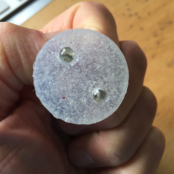
Getting the electronics and programming working was a milestone, next I turned my attention to the casing. My original idea was to have a flexible casing with the LEDs partly encapsulated in the casing. I did some testing using Smooth-On Sorta Clear 37A silicon rubber.
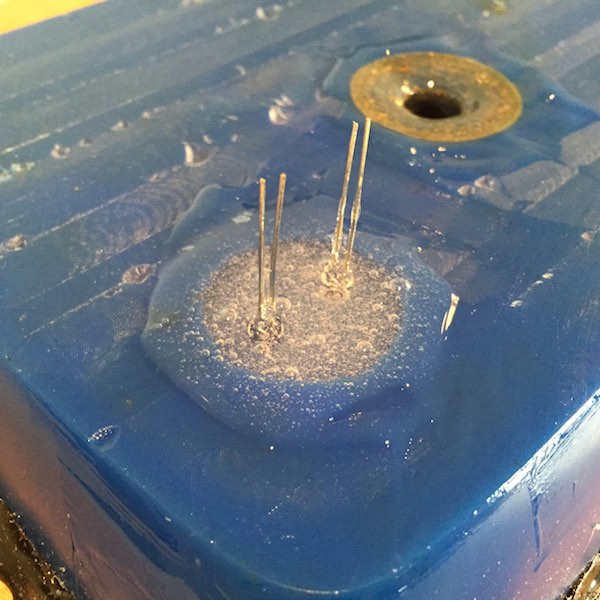
The Sorta Clear worked well and the 37A Shore hardness, the equivalent of a pencil rubber felt about right for the casing. Although I'd encapsulating the LEDs in the silicon rubber the rubber had not bonded to the LED and it was easy to pull out of the token. This could be seen as a feature or a problem when making the top cover, this result is predictable as the data sheet says no mold release is not usually required.
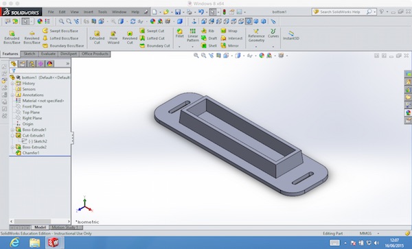
I've struggled with the 3D design aspect of the course and found the learing curve steep with the 3D design software. However I was focused on using Solidworks to make a two-part casing which would house the circuit board, battery, ultrasonic sensor and LED array.
I designed a simple bottom part of the casing with a box to fit the battery and ciruit board.
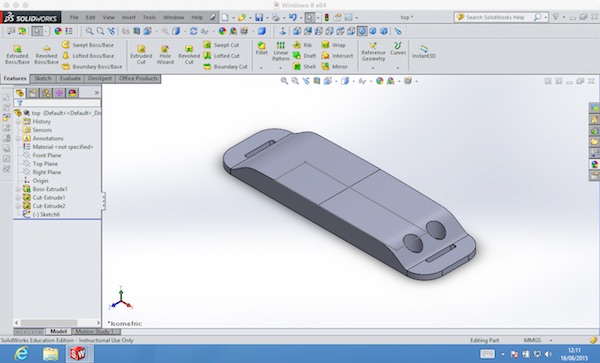
The top half of the casing fitted on top on the bottom half with an internal void to fit over the box part of the bottom casing.
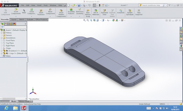
Top and bottom combined into an assembly.
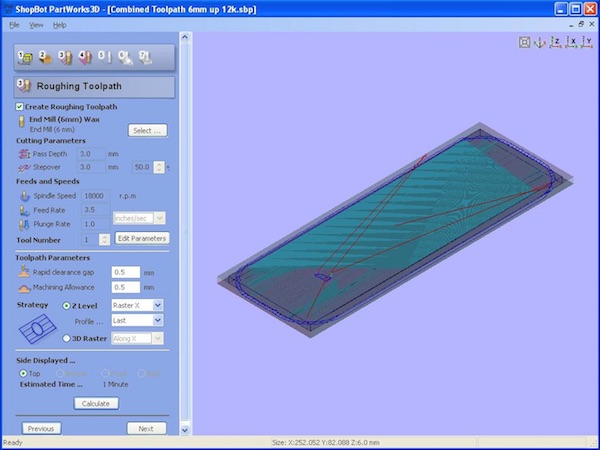
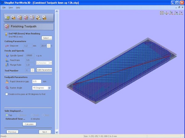
I concentrated on the bottom half of the casing and saved the SolidWorks design as a STL file for milling on the Shopbot.
For milling the machinable wax I used the same mill for both the roughing and finishing cut - a 6mm up-cut end-mill with the following cutting parameters, feeds and speeds:
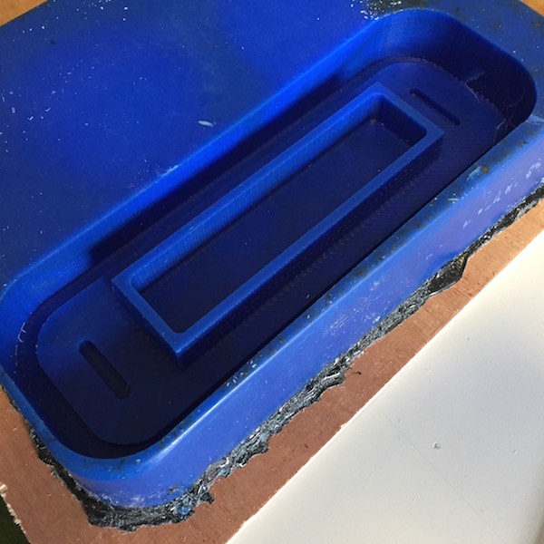
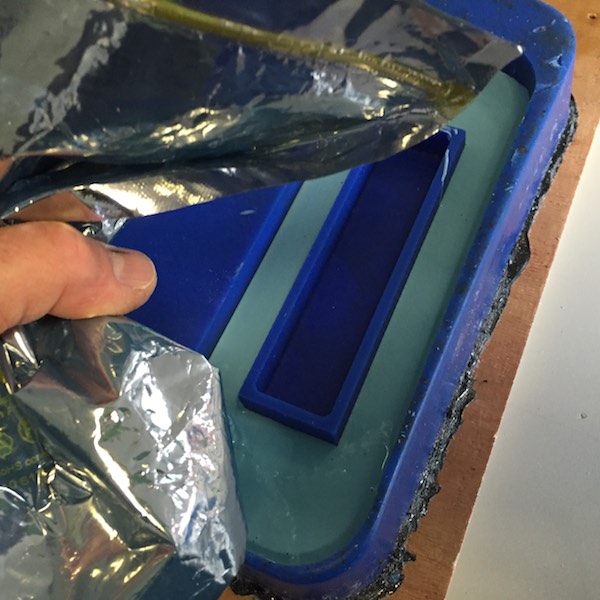
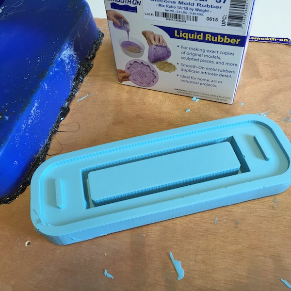
To make the flexible mold I used Smooth-On OOMOO 25 silicon rubber. A top tip from fellow student Sally Williams after mixing the silicon rubber was to put in a plastic bag and cut a small hole in a corner to pipe out the silicon rubber like cake decorating. This method is good for getting into small areas and avoidingair pockets in corners.
After curing overnight the mold was ready for demolding.
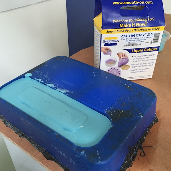
This was a successful result.
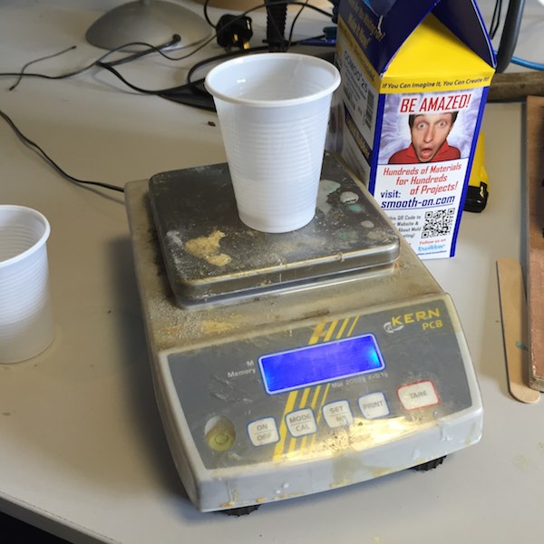
The next step was to cast the bottom casing using Sorta Clear silicon rubber. I measured out parts A and B carefully and mixed well together.
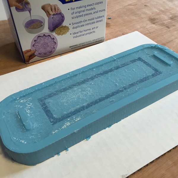
The Sorta Clear behaved differently from the OOMOO when filling the mold being stickier and more viscous. The data sheet gave a cure time of 4 hours to demold, but his could be reduced with "mild heat", the data sheet did not specify what mild heat was though. I put in the oven at the lowest setting to switch the heating elements on and left for 4 hours.
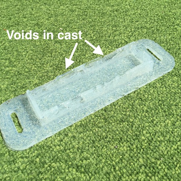
On inspection the exposed surface had cured and was not tacky to touch. So I attempted to demold and found the unexposed faces of the part to be still sticky to touch. So I left the mold overnight and demolded the following morning. The inners faces were still sticky on touch and dissapointingly the faces of the box had plenty of voids in.
With the second attempt at using the Sorta Clear I mixed part A and part B well before measuring out equal amounts and combining and mixing well. This time I used a syringe to slowly fill the channel to try and avoid air pockets from forming
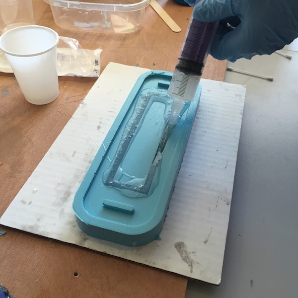
This time I left the Sorta Clear to cure over the weekend.
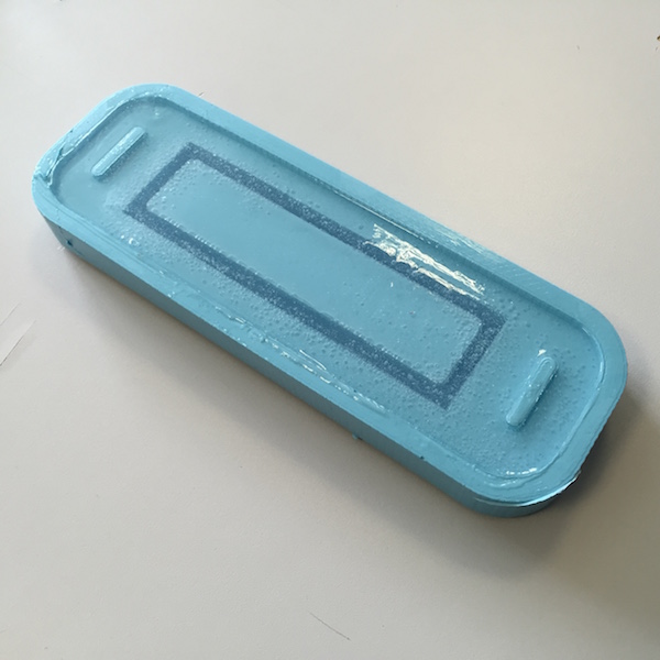
The exposed surface of the cast had cured and was dry on touch, but the same issue happended as before the inner surfaces were still tacky, but not as bad as bad as before.
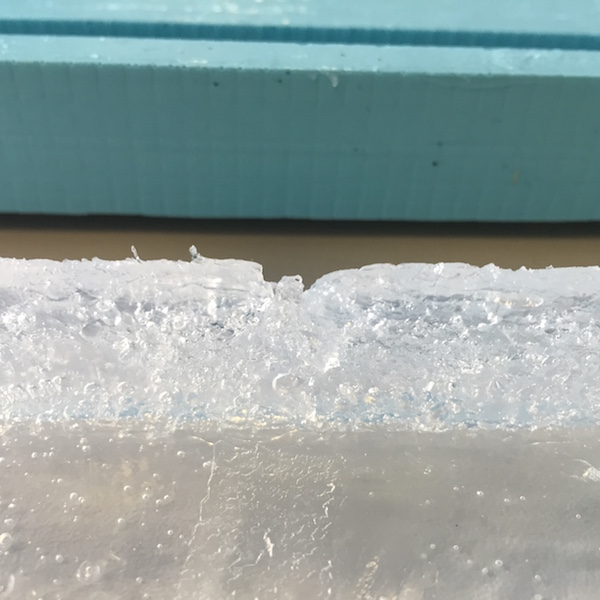
Re-reading the Smooth-On Sorta Clear 37A data sheet - highlighted the problem "Cure Inhibition – Addition-cure silicone rubber may be inhibited by certain contaminants in or on the pattern to be molded resulting in tackiness at the pattern interface or a total lack of cure throughout the mold. Latex, tin-cure silicone, sulfur clays, certain wood surfaces, newly cast polyester, epoxy or urethane rubber may cause inhibition." My initial test with the Sort Clear had been in machinable wax, not silicon rubber. This was a lesson learnt of testing each seperate stage of the process and not assuming similar processes behave in the same way.
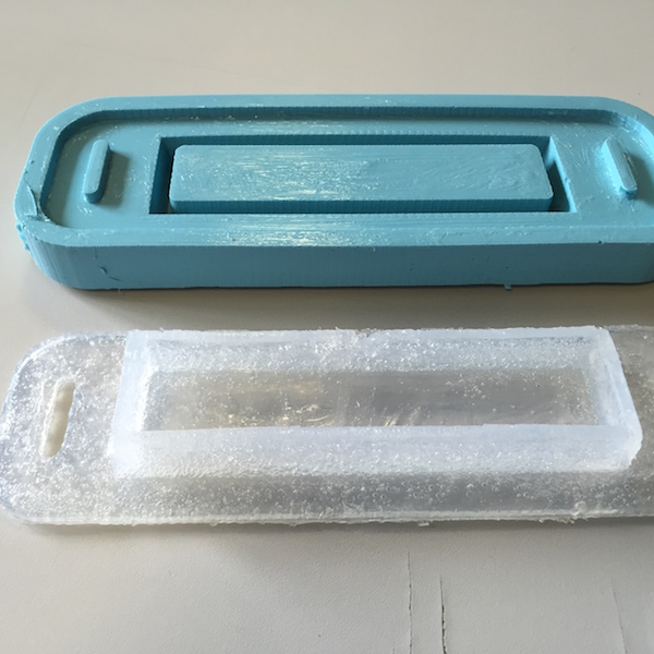
After removing the bottom part of the casing form the mold and leaving to cure overnight, the tacky faces started to cure.
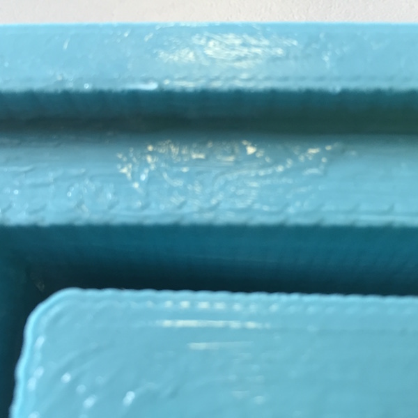
Another lesson learnt using the Sorta Clear 37A was the stiffness of the small token (50mm diameter) felt about right the larger bottom piece (240x60mm) was too flexible and should have been made in a harder silicon rubber. Although the next hardness up in the Sorta Clear was Shore hardness 40A not a large increment, so perhaps a translucent material was the wrong material choice for the casing. Or at least a harder bottom casing to give more support to a translucent top casing.
Having been disappointed with the results of the molding and casting and running out of the Sorta Clear 37A and time. I did not have chance to make the top part of the casing. I would adopt a different material choice when taking this forward.
Downloadable design files at the bottom of the pageMechanical design
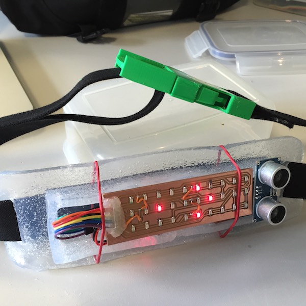
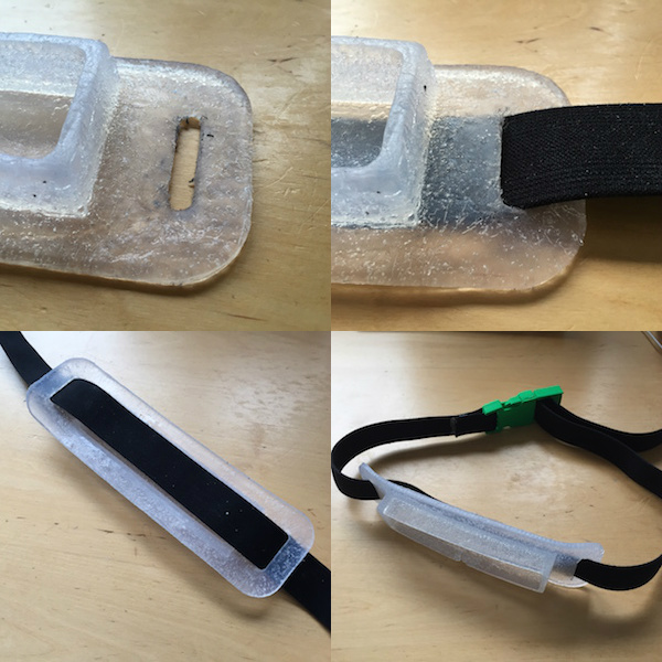
The casing was secured to the strap using two 32x5mm threading the elastic webbing through. This worked well and allowed removal and adjustment. The strap also acts to secure the upper casing to the lower casing when the bike light is worn on the back.
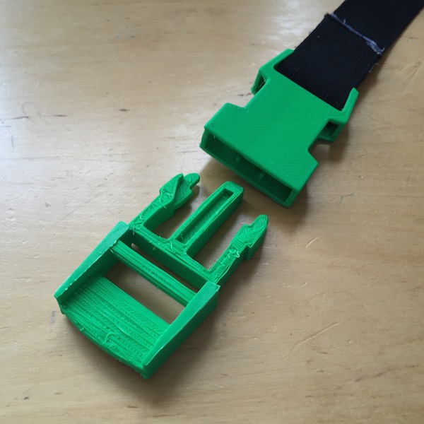
Buckle
The concept of the bike light was a wearble belt device, being higher off the ground that traditional bike lights on the frame or seat post and hence more visible to car drivers.
I thought of using a quick release snap-lock buckle to make it easy to clip and unclip the bike light strap. I used a Thinkiverse buckle as a starting point and imported it into SolidWorks to change the dimensions to fit the 32mm elastic webbing strap.
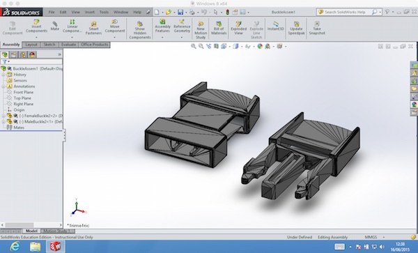
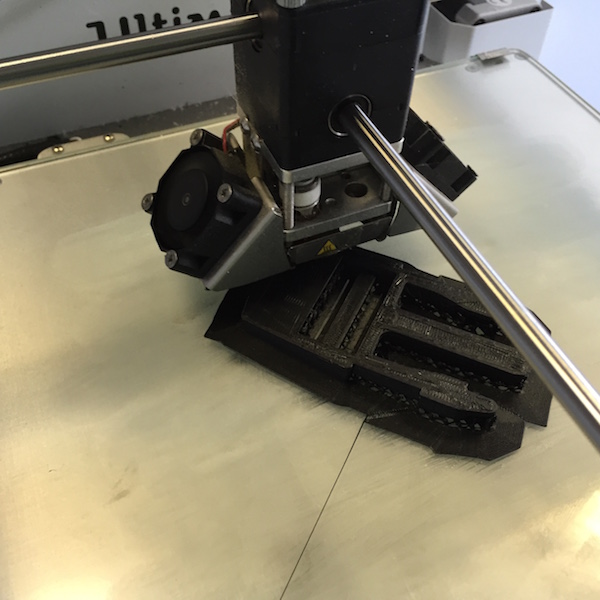
After saving as an STL file I then printed the male part of the buckle on the Ultimaker.
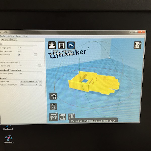
The Ulitmaker 3D printer had been playing up as was the case trying to print the buckle.
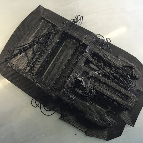
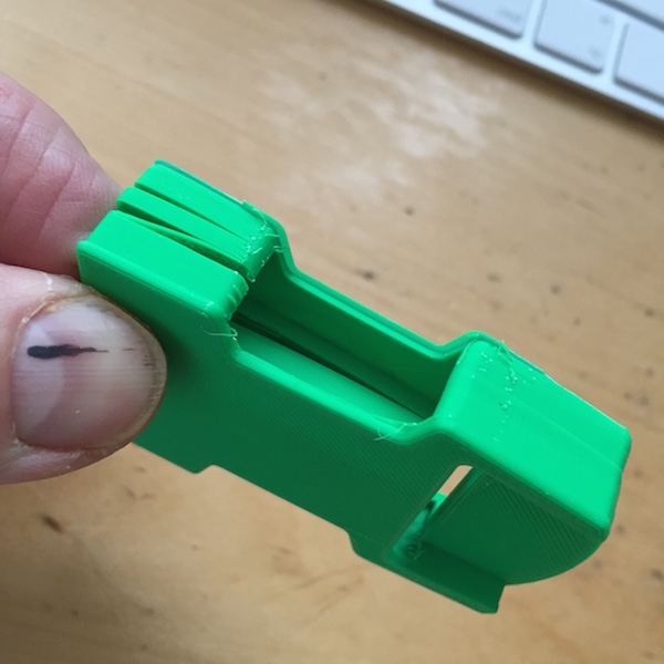
One of my colleagues David Mason offered to print the buckle on his home 3D printer with more success.
 Downloadable design files at the bottom of the page
Logo
I created a logo in Inkscape by modifying a bitmap image of a pronghorn and converting the bitmap into a vector and changing objects to a path.
The default vinyl cutter settings 20cm/s and 90gf worked well for the white vinyl and carefully removing surplus parts and putting on transfer tape I put on the front of the buckle.
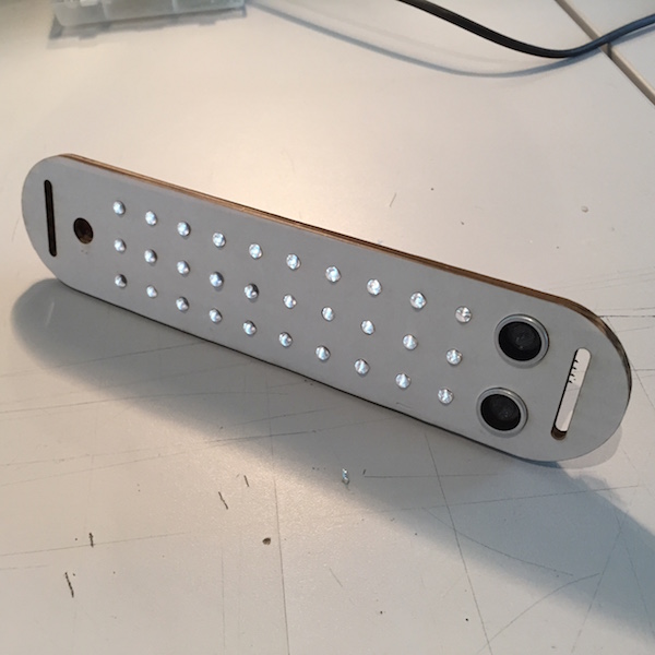
Prototype
On the 10th June I demonstrated the prototype bike light working.
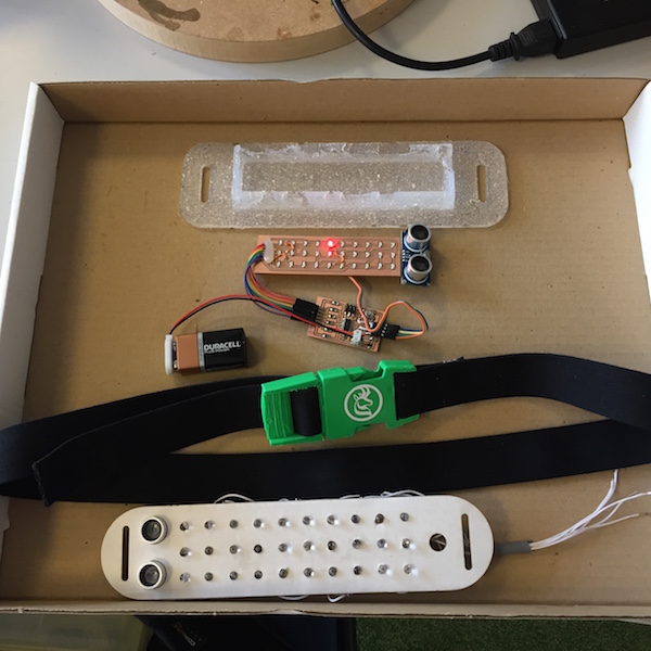
Demo of Pronghorn bike light
Object approaching bike light changes the display pattern.
Conclusions
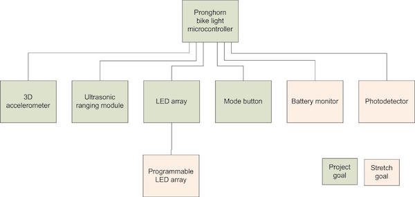
Updated systems/goals diagram
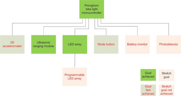
Although a number of the goals were not achieved, the integration of input, output devices and casing was, which gave a greater appreciation of how to integrate electronics into a product.
Updated bill of materials
The following table gives an updated bill of materials and budget for the final project. The budget was $21.95 compared to the original $49.03 a 55% reduction.
| Materials/components | Source | Cost |
|---|---|---|
| FR1 3"x2", 2x | FabLab inventory | $0.36 |
| LEDs, red, 30x | FabLab inventory | $3.90 |
| ATTINY44A-SSU-ND | FabLab inventory | $1.18 |
| Other electronic components | FabLab inventory | $2.00 |
| Ultrasonic ranging module HC-SR04 | eBay | $2.99 |
| Smooth-On SORTA Clear 37 | FabLab inventory | $8.00 |
| 3D printed buckle | FabLab inventory | $1.00 |
| Vinyl | FabLab inventory | $1.00 |
| Sub-total | $20.43 | |
| Elastic webbing | Abbey Saddlery | $1.50 |
| 9V battery snap with 2pc molded | FabLab inventory | $0.52 |
| 9V battery | eBay | $1.00 |
| Sub-total | $1.52 | |
| Budget total cost | $21.95 |
The final project was a rush to pull everything together and get something working, the spiral development process certainly helped. Althought I reduced the number of goals as I had spent more time on the LED Charlieplex array than I had budgeted. I have been able to demostrate a proof of concept, allbeit a long way from a functional product.
Looking to move the project forward I would step back and revisit a number of areas.
- a more thorough requirements capture, including regulations and safety requirements
- investigate conventional multiplexing rather than Charlieplexing
- spend more time investigating how to use copper traces
- look at alternative casing materials such as composities?
- include more input devices such as a 3D-accelerometer
The final project has been a salutary lesson, in not how we do things, but why we do things and the fear of what holds us back. The challenge of turning and idea into a physical device was a greater challenge than I had anticapated in terms of time, persistence and motivation. Perhaps age isn't on my side on this one! The whole experience has given me a greater appreciation and admiration of creative designers and engineers who can make almost anything.
Downloadable design and program files
Program file
C program file - hello.array.44.cEagle design files
Eagle design file - finalATtiny44_5.brdEagle design file - finalATtiny44_5.sch
Eagle design file - finalLed_1x.brd
Eagle design file - finalLed_1x.sch
Eagle design file - finalLed_7.brd
Eagle design file - finalLed_7.sch
Eagle design file - newMega.brd
Eagle design file - newMega.sch
Eagle design file - testCharlie6.brd
Eagle design file - testCharlie6.sch
Eagle design file - testCharlie7.brd
Eagle design file - testCharlie7.sch
Eagle export file - LedArrayCopperTraces.png
Eagle export file - testCharlie6.png
Eagle export file - testCharlie6outline.png
Inkscape files
Inkscape file - LedSpacerPlate.svgInkscape file - mockup.svg
Inkscape file - pronghornVinyl1.svg
SolidWorks STL files
SolidWorks export file - bottom1.STLSolidWorks export file - top.STL
SolidWorks export file - FemaleBuckle2.STL
SolidWorks export file - MaleBuckle2.STL