
Week 11 - input devices (Apr 8)
Assignment
This weeks assignment was to design, make and programme a circuit board that uses an input device.
Input device
I plan to use pressure sensors in my final project to sense which part of the foot is making contact with the ground when running. So using a pressur sensor as an input device looks a good choice to learn more about how to use them.
At last week's review I presented my final project idea and Neil gave me a couple of good refernces one for multi-compound soles and one for a shoe insert pressure sensor array by Sam Calisch, one of Neil's grad students who did the MAS.863 course in 2012.
Applying spiral development pricinciples my goal was to start with one simple pressure sensor before increasing complexity with multiple sensors and multiplexing input arrays.
Circuit board design
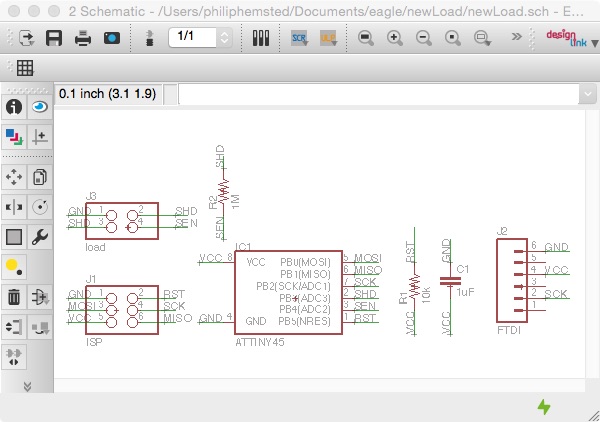
I'm very much a beginner with electronics, so used Neil's hello.load.45 board as a starting point for my own design. I went through the steps of creating a schematic using Eagle and laying out and routing the board in the board window. I used angles tracks to route the nets.
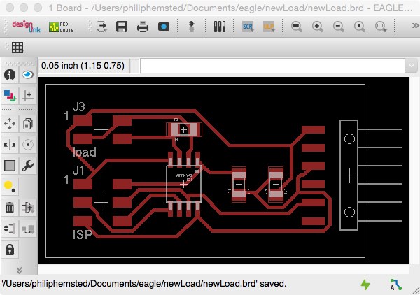
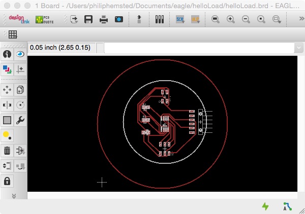
I tried an experiment with a circular board design. But found the nets more difficult to route with the way I'd orientated the components so decided to mill the initial rectangular board design.
It was a few weeks since I'd used Eagle to design a circuit board and to begin with I'd forgot to check the Design Rules, especially the minimum clearance between objects in signal layers. The default is 8mil (thousands of an inch) for wires, pads and vias, I increased this to 16mil (0.4mm) to allow for 1/64th inch tool diameter.
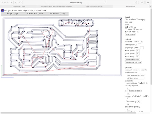
I then created a cutout file for the hello load board by exporting the top layer as an image to png (monchrome 500 dpi) and then opened the png file in GIMP to add text to the board. I expanded the canvas size by 40 px and centred and then flattened the image to create a rectangle with a white boarder. I copied the filed and filled in the traces and text with the bucket and saved the outline of the board as a png.
Milling circuit board
When setting up to mill the board using fabmodules,org and the Modella I realised I'd milled the outline with the traces, bit decided to continue and milled the outline with the 1/32th mill.
The sacrificial bed of the Modella had be used a lot since the last time I'd milled a board so I took extra care to lay the blank board on the bed and press down with the felt pad.
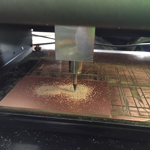
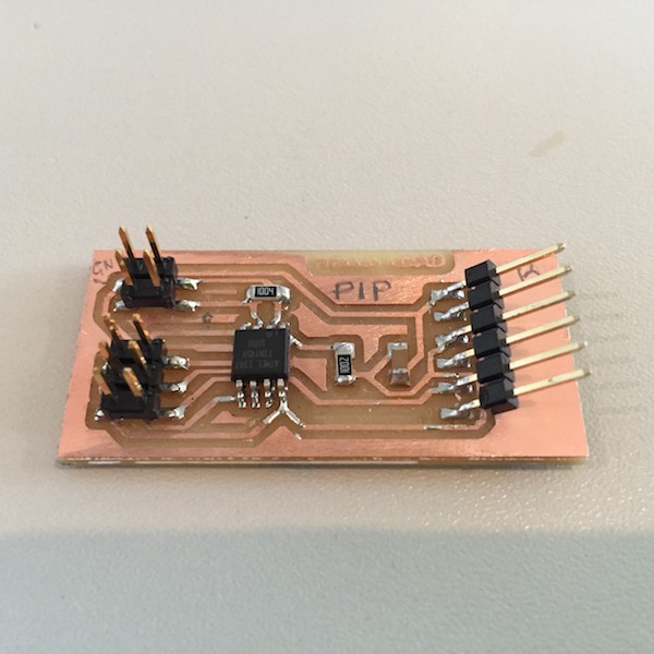
The board milled cleanly and then I stuffed the board with the components, taking care to get the ATtiny 45 chip in the right orientation.
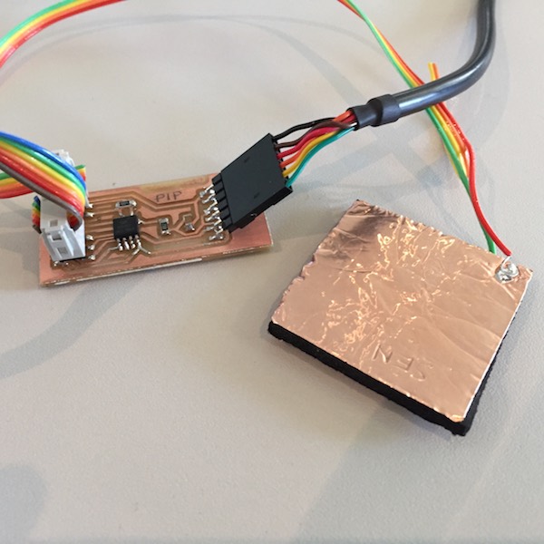
Pressure sensor
To make the step response pressure sensor I used self adhesive copper foil and 3.5mm neoprene rubber sheet to separate the sensor and ground plates. I chose neoprene as a being easy to compress and had some spare from repairing my wetsuit. The first sensor I made was a 40mm2 square 4mm thick, which compressed down to 2mm thick.
Programming
I downloaded and installed PySerial on my MacBookPro with the help of the following tutorial to enable Neil's Python visualisation program for measuring and displaying the step response of the pressure sensor.
To install, open terminal and move to directory and type:
sudo python setup.py install
I'd previously installed CrossPack the Amtel development environment for OS X and used Neil's code example, by typing the following terminal commands.
cd desktop/hello-load
sudo make -f hello.load.45.make make program-usbtiny
ls /dev/tty.usb*
python hello.load.45.py /dev/cu.usbserial-FTHHRP08
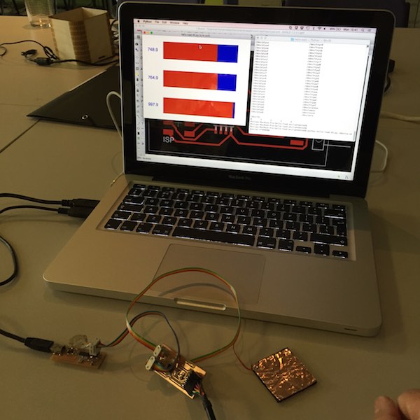
This opens a window showing three bar graphs representing voltage measured at different time intervals. The horizontal scale is 0-1023k, 0 for OV and 1023 for 5V. The three bars represent different time instances of measuring the voltage on pin PB4 at 1, 10 and 100 milliseconds.
Here's a picture of the pressure sensor (with only the sensor connected to pin PB4) measuring ambient conditions. The graph shows at 1 millisecond the voltage was 748.9/1023 = 73% of 5V or 3.7V, at 10 milliseconds 764.9/1023 = 75% of 5V or 3.7V and at 100 milliseconds 997.9/1023 =98% or 4.9V.
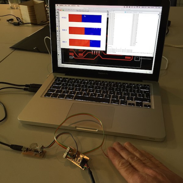
Here's a picture of the pressure sensor (with only the sensor connected to pin PB4) measuring my hand touching the sensor. As I've increased the effective area of the sensor the timetaken to charge up to 5V has increased, the 1 millisecond measurement is 418.0/1023 = 41% of 5V or 2V.
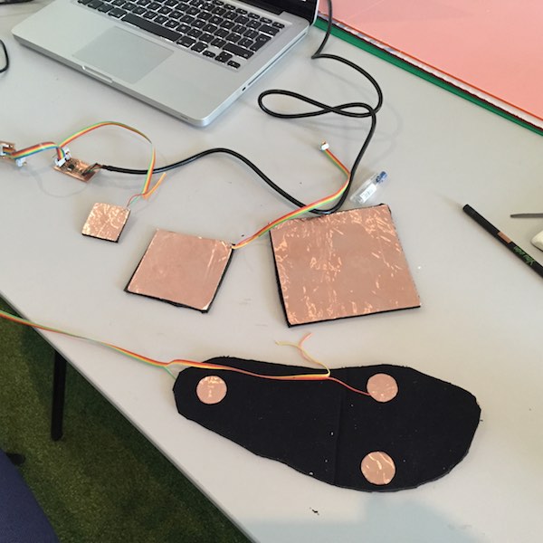
I then experimented with different sized sensors 40mm2, 80mm2 and 120mm2 and a foot shaped pad with 25mm circular sensors and ground. The times were similar, what I did notice is with the largest 120mm2 sensor the measurements were less stable and fluctuated by up to 25% on all three readings.
I then connected the ground of the 40mm2 sensor to see whether there was an effect with foot pressure on the sensor.
This picture shows the bars from standing lightly on the sensor.
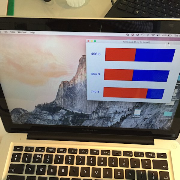
This picture shows the bars from standing with full weight on one foot on the sensor.
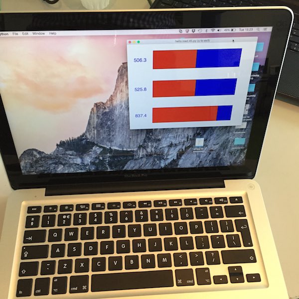
There is a difference with the full weight condition taking more time to charge. For example at the 10 millisecond measurement light weight pressure measured 525.8/1023 or 2.6V and full weight pressure measured 456.5/1023 or 2.2V. Showing that the capacitance of the sensor increased with pressure.
Downloadable files
Eagle board newLoad.brd
Eagle schematic newLoad.sch
newLoadTraces.png
newLoadOutline.png