
Week 14 - networking and communications (Apr 29)
Assignment
This week's assignment is to design and build a wired or wireless network connecting at least two processors.
Having no previous experience of networking and communications I decided to make the example RS-232 bridge and two nodes.
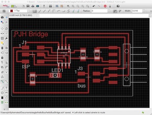
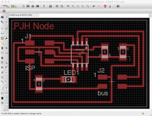
Circuit board design
I designed the Bridge and Node boards in Eagle and milled the traces out on the Modella.
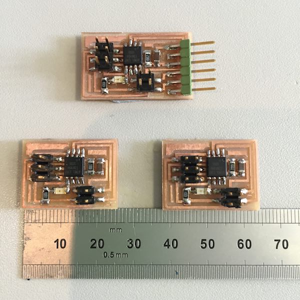
Stuffing circuit boards
The boards milled cleanly and I stuffed the board with the components, taking care to get the ATtiny 45 chip in the right orientation.
Programming
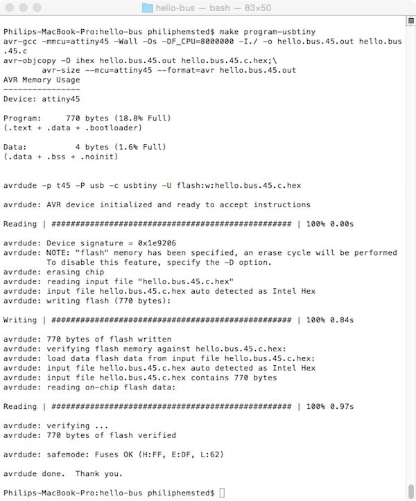
To begin with I flashed Neil's C code onto the bridge board with the Fab ISP
            cd desktop/hello-bus
            cp hello.bus.45.make makefile
            make program-usbtiny
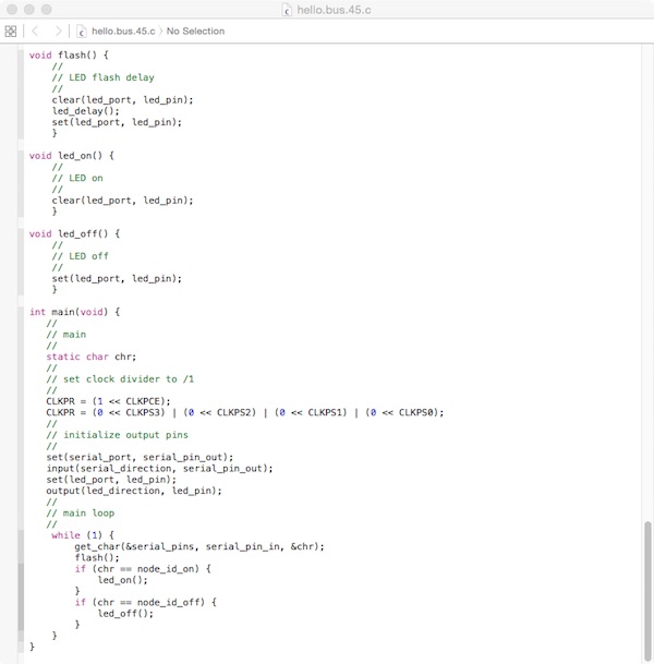
I then modified Neil's C code on line 41 #define node_id '0' to change the node_id to '1' and then to '2' for the node boards and flashed the code onto the boards.
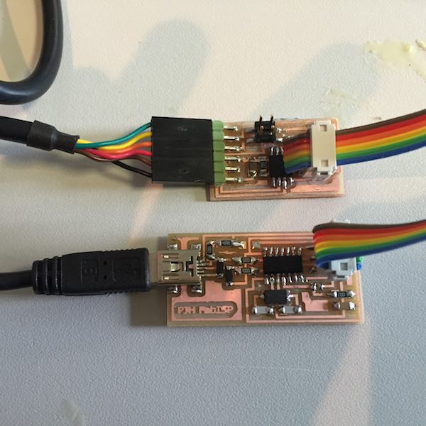
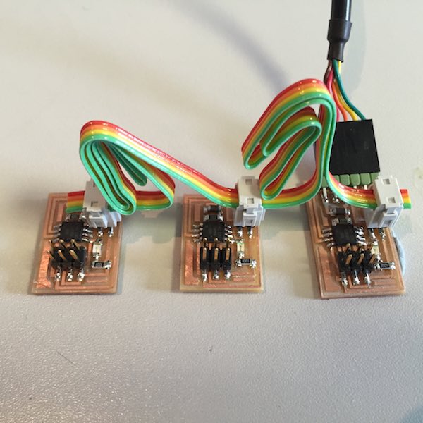
Networking
The boards were connected with a 3 wire ribbon cable making sure the connectors are the right way round.
The Arduino serial monitor was used to send characters to the boards
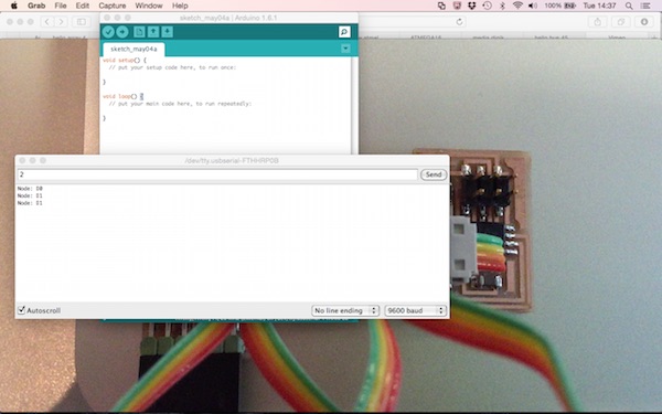
Video showing a character '0' sent flashes all the nodes and then the bridge flashes again. Sending a character '1' flashes all the nodes and then node 1 flashes again. Sending a character '2' flashes all the nodes and then node 2 flashes again. Finally sending a '3' character all nodes flash to say they have received a character, but as it does not match the node id no nodes flash again
Here's what's happening in the code, the master (laptop) sends a character to the slave nodes, who then flash to say they have received a character. The if statement in the code checks to see if the character corresponds to the node address the LED flashes again.
Changing the code
After seeing how the code worked I modified the code to to switch the LEDs on and off individually.
            #define node_id_on '0'
            #define node_id_off '1'
Video showing a character '0' switching on the bridge and a character '1' switching it off. Similarly sending characters 2 and 3 switches on and off node 1 and characters 4 and 5 switches on and off node 2.
Lessons learnt
With no previous experience of networking I was able to create a simple network using RS-232 serial communication with three nodes driven from my laptop. I modified the code to so communication from the laptop could address individual nodes and also how the individual nodes responded.
Downloadable design and program files
helloBusBridge.sch
helloBusBridge.brd
helloBusNode.sch
helloBusNode.brd
hello.bus.45.c