
Week 12 - output devices (Apr 15)
Assignment
This week's assignment is to add an output device to a microcontroller board you've designed and program it to do something.
I decided on the LED array for an output device as I was interested in learning about how to drive multiple LEDs with a small number of pins. Neil introduced the method of doing this called 'Charlieplexing'.
Design
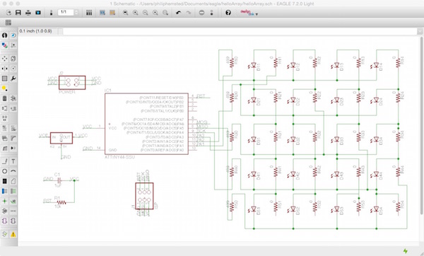
I redesigned Neil's LED array board in Eagle. This was more complex than previous boards with the number of components and making sure the array was correct
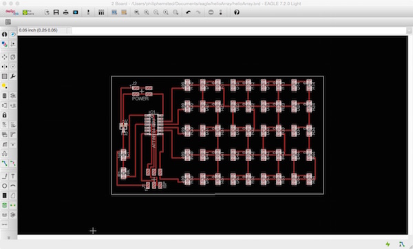
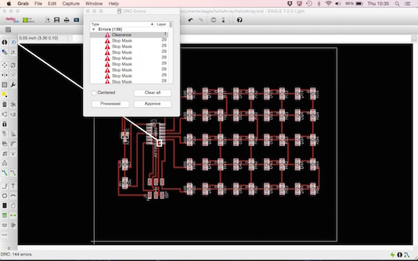
When I checked the board with the design rules, a number of clearance errors flagged up. I was able to remove these with reducing the size of the Alt grid and moving the traces until the three traces fitted under the ATtiny44 microprocessor.
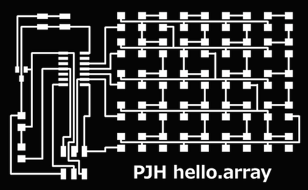
I had more of a problem with the trace between the 5V regulator and resorted to modified the pads in Gimp to achieve the tool path in Fabmodules.
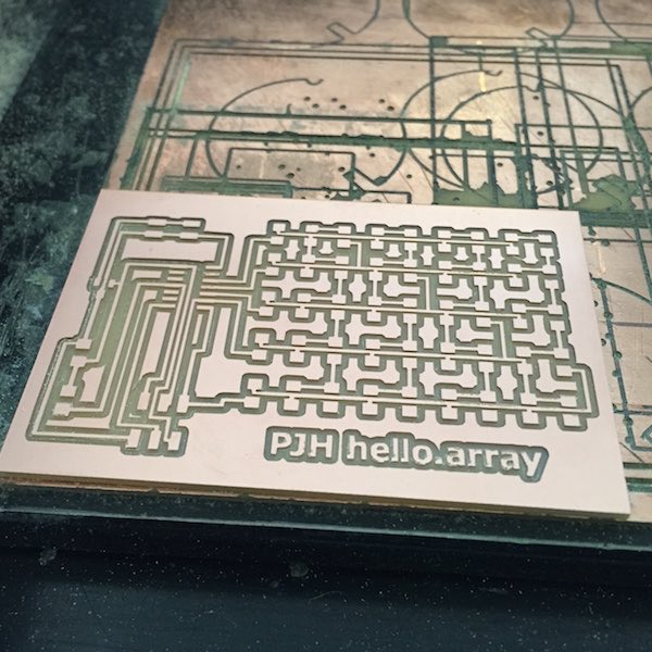
Milling
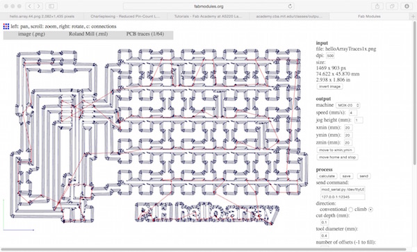
As with last week's input devices I used Fabmodules and the Modella to mill the board. As the board was large it fitted onto a blank without the need for milling an outline.
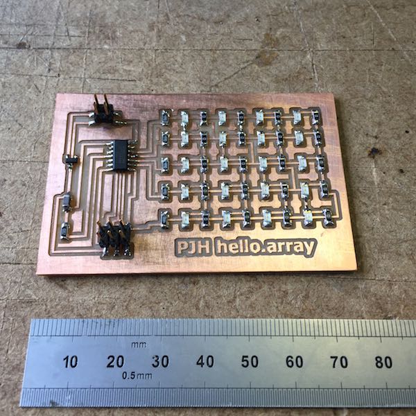
Stuffing board
I was surprised how easy it was to stuff the board despite having 51 components. I was able to get into a rytham soldering the array resistors and LEDs by pre-dabbing pads and then going on column at at time.
Programming board
I tried to programming the hello array board using the Fab ISP and Neil's initial program. The first time I tried it it failed.
Philips-MacBook-Pro:~ philiphemsted$ cd desktop/hello-array
Philips-MacBook-Pro:hello-array philiphemsted$ cp hello.array.44.make makefile
Philips-MacBook-Pro:hello-array philiphemsted$ make program-usbtiny
avr-objcopy -O ihex hello.array.44.out hello.array.44.c.hex;\
	avr-size --mcu=attiny44 --format=avr hello.array.44.out
AVR Memory Usage
----------------
Device: attiny44

Program:     368 bytes (9.0% Full)
(.text + .data + .bootloader)

Data:          1 bytes (0.4% Full)
(.data + .bss + .noinit)


avrdude -p t44 -P usb -c usbtiny -U flash:w:hello.array.44.c.hex


avrdude: error: usbtiny_receive: usb_control_msg(DeviceRequestTO): unknown error (expected 4, got -1)
avrdude: AVR device initialized and ready to accept instructions

Reading |                                                    | 0% 0.00s
avrdude: error: usbtiny_receive: usb_control_msg(DeviceRequestTO): no connection to an IOService (expected 4, got -6)
avr_read(): error reading address 0x0000
    read operation not supported for memory "signature"
avrdude: error reading signature data for part "ATtiny44", rc=-2
avrdude: error reading signature data, rc=-1

avrdude: error: usbtiny_transmit: usb_control_msg(DeviceRequestTO): no connection to an IOService

avrdude done.  Thank you.

make: *** [program-usbtiny] Error 1
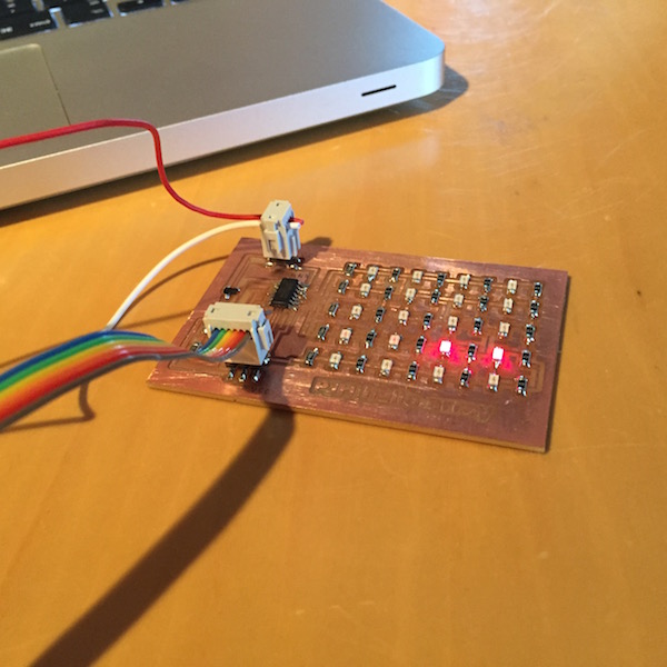
After disconnecting and connecting the cables and connectors, it worked, the programe loaded onto the hello array board!
Philips-MacBook-Pro:~ philiphemsted$ cd desktop/hello-array
Philips-MacBook-Pro:hello-array philiphemsted$ cp hello.array.44.make makefile
Philips-MacBook-Pro:hello-array philiphemsted$ make program-usbtiny
avr-objcopy -O ihex hello.array.44.out hello.array.44.c.hex;\
	avr-size --mcu=attiny44 --format=avr hello.array.44.out
AVR Memory Usage
----------------
Device: attiny44

Program:     368 bytes (9.0% Full)
(.text + .data + .bootloader)

Data:          1 bytes (0.4% Full)
(.data + .bss + .noinit)


avrdude -p t44 -P usb -c usbtiny -U flash:w:hello.array.44.c.hex

avrdude: AVR device initialized and ready to accept instructions

Reading | ################################################## | 100% 0.00s

avrdude: Device signature = 0x1e9207
avrdude: NOTE: "flash" memory has been specified, an erase cycle will be performed
         To disable this feature, specify the -D option.
avrdude: erasing chip
avrdude: reading input file "hello.array.44.c.hex"
avrdude: input file hello.array.44.c.hex auto detected as Intel Hex
avrdude: writing flash (368 bytes):

Writing | ################################################## | 100% 0.38s

avrdude: 368 bytes of flash written
avrdude: verifying flash memory against hello.array.44.c.hex:
avrdude: load data flash data from input file hello.array.44.c.hex:
avrdude: input file hello.array.44.c.hex auto detected as Intel Hex
avrdude: input file hello.array.44.c.hex contains 368 bytes
avrdude: reading on-chip flash data:

Reading | ################################################## | 100% 0.45s

avrdude: verifying ...
avrdude: 368 bytes of flash verified

avrdude: safemode: Fuses OK (H:FF, E:DF, L:62)

avrdude done.  Thank you.
The excitment was even greater than the hello board getting to see the array flash a pattern.
My next task was to amend Neil's code to try and make the array flash a different pattern. A previous Fab Academy student Astrid Lubsen made a helpful table to help reference the LEDs for her hello Array board - Astrid's output device.
| BA | CA | DA | EA |
| AB | CB | DB | EB |
| AC | BC | DC | EC |
| AD | BD | CD | ED |
| AE | BE | CE | DE |
I worked through the 4x5 array and commented out the LEDs that were off and copied the lines of code and repeated.
// // // hello.array.44.c // // Charlieplex LED array hello-world // // Neil Gershenfeld // 11/13/10 // // (c) Massachusetts Institute of Technology 2010 // This work may be reproduced, modified, distributed, // performed, and displayed for any purpose. Copyright is // retained and must be preserved. The work is provided // as is; no warranty is provided, and users accept all // liability. // // Philip Hemsted // 04/20/15 // Amend code to make array flash chevrons // #include#include #define output(directions,pin) (directions |= pin) // set port direction for output #define input(directions,pin) (directions &= (~pin)) // set port direction for input #define set(port,pin) (port |= pin) // set port pin #define clear(port,pin) (port &= (~pin)) // clear port pin #define pin_test(pins,pin) (pins & pin) // test for port pin #define bit_test(byte,bit) (byte & (1 << bit)) // test for bit set #define led_delay() _delay_ms(1) // LED delay #define led_port PORTA #define led_direction DDRA #define A (1 << PA1) // row 1 #define B (1 << PA2) // row 2 #define C (1 << PA3) // row 3 #define D (1 << PA4) // row 4 #define E (1 << PA5) // row 5 void flash(uint8_t from, uint8_t to, uint8_t delay) { // // source from, sink to, flash // static uint8_t i; set(led_port,from); clear(led_port,to); output(led_direction,from); output(led_direction,to); for (i = 0; i < delay; ++i) led_delay(); input(led_direction,from); input(led_direction,to); } void led_cycle1(uint8_t number, uint8_t delay) { // // cycle through LEDs // uint8_t i; for (i = 0; i < number; ++i) { flash(B,A,delay); //flash(C,A,delay); //flash(D,A,delay); //flash(E,A,delay); //flash(A,B,delay); flash(C,B,delay); //flash(D,B,delay); //flash(E,B,delay); //flash(A,C,delay); //flash(B,C,delay); flash(D,C,delay); //flash(E,C,delay); //flash(A,D,delay); flash(B,D,delay); //flash(C,D,delay); //flash(E,D,delay); flash(A,E,delay); //flash(B,E,delay); //flash(C,E,delay); //flash(D,E,delay); // each LED has a two letter name, in this way you can address each // LED by flashing its letter code } } void led_cycle2(uint8_t number, uint8_t delay) { // // cycle through LEDs // uint8_t i; for (i = 0; i < number; ++i) { //flash(B,A,delay); flash(C,A,delay); //flash(D,A,delay); //flash(E,A,delay); //flash(A,B,delay); //flash(C,B,delay); flash(D,B,delay); //flash(E,B,delay); //flash(A,C,delay); //flash(B,C,delay); //flash(D,C,delay); flash(E,C,delay); //flash(A,D,delay); //flash(B,D,delay); flash(C,D,delay); //flash(E,D,delay); //flash(A,E,delay); flash(B,E,delay); //flash(C,E,delay); //flash(D,E,delay); } } void led_cycle3(uint8_t number, uint8_t delay) { // // cycle through LEDs // uint8_t i; for (i = 0; i < number; ++i) { //flash(B,A,delay); //flash(C,A,delay); flash(D,A,delay); //flash(E,A,delay); //flash(A,B,delay); //flash(C,B,delay); //flash(D,B,delay); flash(E,B,delay); flash(A,C,delay); //flash(B,C,delay); //flash(D,C,delay); //flash(E,C,delay); //flash(A,D,delay); //flash(B,D,delay); //flash(C,D,delay); flash(E,D,delay); //flash(A,E,delay); //flash(B,E,delay); flash(C,E,delay); //flash(D,E,delay); } } void led_cycle4(uint8_t number, uint8_t delay) { // // cycle through LEDs // uint8_t i; for (i = 0; i < number; ++i) { //flash(B,A,delay); //flash(C,A,delay); //flash(D,A,delay); flash(E,A,delay); flash(A,B,delay); //flash(C,B,delay); //flash(D,B,delay); //flash(E,B,delay); //flash(A,C,delay); flash(B,C,delay); //flash(D,C,delay); //flash(E,C,delay); flash(A,D,delay); //flash(B,D,delay); //flash(C,D,delay); //flash(E,D,delay); //flash(A,E,delay); //flash(B,E,delay); //flash(C,E,delay); flash(D,E,delay); } } int main(void) { // // set clock divider to /1 // CLKPR = (1 << CLKPCE); CLKPR = (0 << CLKPS3) | (0 << CLKPS2) | (0 << CLKPS1) | (0 << CLKPS0); // // main loop // while (1) { led_cycle1(10,5); led_cycle2(10,5); led_cycle3(10,5); led_cycle4(10,5); //led_cycle(1,100); // going through the arrary 1 time with a delay of 100 //led_cycle(3,20); // going through the arrary 3 times with a delay of 20 //led_cycle(100,1); // going through the arrary 100 times with a delay of 1 } }
Video of hello array
Video of LED array flashing chevrons
Downloadable design and program files
Eagle board helloArray.brd
Eagle schematic helloArray.sch
helloArrayTraces.png
Modified hello.array.44.c