
Week 15 - interface and application programming (May 6)
Assignment
This weeks assignment was to write an application that interaces with an input and/or output device.
I haven't written written any graphical applications or used Processing, Python or Javascript in anger. So decided to use Processing as an introduction to application programming as it had a similar look and feel to the Arduino IDE and plenty of examples.
My initial thought was to make an application for the LED array I made in the Output week as I'm planning to use an LED array in my final project. So I decided to investigate Processing for a simple user interface to the LED array.
Hardware
I used the hello array board I made in Output Devices week.
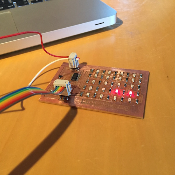
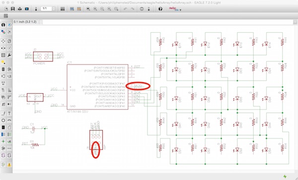
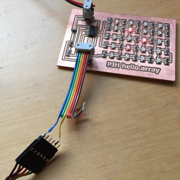
The hello array board did not have a FTDI header for serial communication, so I made up a cable to use the ISP header to connect the free pin PA6 (MOSI) on the ATTINY44a not used for Charlieplexing to enable serial communication between the board and the computer.
I also connected the GND pin, but not VCC as the hello array board already had power from the battery.
Processing Application
Firstly I updated the hello array C code adding the serial port used in Neil's code for the phototransistor hello-world board code here making sure serial definitions pointed to the right port and pin. I then flashed the code onto the hello array board with the FabISP.
Code added to enable the hello array board to communicate to the Processing sketch.
#define bit_delay_time 102 // bit delay for 9600 with overhead
#define bit_delay() _delay_us(bit_delay_time) // RS232 bit delay
#define half_bit_delay() _delay_us(bit_delay_time/2) // RS232 half bit delay
#define char_delay() _delay_ms(10) // char delay

#define serial_port PORTA
#define serial_direction DDRA
#define serial_pin_out (1 << PA6)
void put_char(volatile unsigned char *port, unsigned char pin, char txchar) {
    //
    // send character in txchar on port pin
    //    assumes line driver (inverts bits)
    //
    // start bit
    //
    clear(*port,pin);
    bit_delay();
    //
    // unrolled loop to write data bits
    //
    if bit_test(txchar,0)
        set(*port,pin);
    else
        clear(*port,pin);
    bit_delay();
    if bit_test(txchar,1)
        set(*port,pin);
    else
        clear(*port,pin);
    bit_delay();
    if bit_test(txchar,2)
        set(*port,pin);
    else
        clear(*port,pin);
    bit_delay();
    if bit_test(txchar,3)
        set(*port,pin);
    else
        clear(*port,pin);
    bit_delay();
    if bit_test(txchar,4)
        set(*port,pin);
    else
        clear(*port,pin);
    bit_delay();
    if bit_test(txchar,5)
        set(*port,pin);
    else
        clear(*port,pin);
    bit_delay();
    if bit_test(txchar,6)
        set(*port,pin);
    else
        clear(*port,pin);
    bit_delay();
    if bit_test(txchar,7)
        set(*port,pin);
    else
        clear(*port,pin);
    bit_delay();
    //
    // stop bit
    //
    set(*port,pin);
    bit_delay();
    //
    // char delay
    //
    bit_delay();
}
   // initialize output pins
   //
   set(serial_port, serial_pin_out);
   output(serial_direction, serial_pin_out);
   //
   // main loop
   //
   while (1) {
      led_cycle1(10,5);
      put_char(&serial_port, serial_pin_out, '1');
      char_delay();
      led_cycle2(10,5);
      put_char(&serial_port, serial_pin_out, '2');
      char_delay();
      led_cycle3(10,5);
      put_char(&serial_port, serial_pin_out, '3');
      char_delay();
      led_cycle4(10,5);
      put_char(&serial_port, serial_pin_out, '4');
      char_delay();
      put_char(&serial_port, serial_pin_out, 10);
      char_delay();
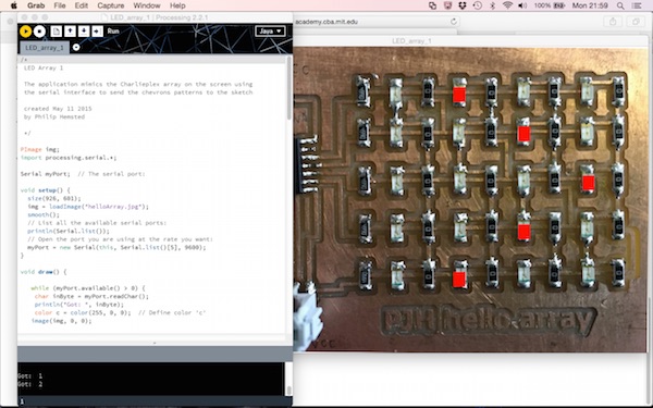
The Processing sketch receives a character 1, 2, 3 or 4 over the serial port and then replicate the pattern being flashed on the hello array board on an image of the board depending on the character being sent.
processing codeLED_array_1
02
03
04
05
06
07
08
09
10
11
12
13
14
15
16
17
18
19
20
21
22
23
24
25
26
27
28
29
30
31
32
33
34
35
36
37
38
39
40
41
42
43
44
45
46
47
48
49
50
51
52
53
54
55
56
57
58
59
60
61
62
63
64
65
66
67
68
69
70
71
72
73
74
75
76
77
78
79
80
81
82
83
84
85
86
87
88
89
90
91
92
93
94
95
96
97
98
99
100
101
102
103
104
105
106
107
108
109
110
111
112
113
114
115
116
117
118
119
120
121
122
123
124
125
126
127
128
129
130
131
132
133
134
135
136
137
138
139
140
141
142
143
/*
 LED Array 1

 The application mimics the Charlieplex array on the screen using
 the serial interface to send the chevrons patterns to the sketch

 created May 11 2015
 by Philip Hemsted

 */

PImage img;
import processing.serial.*;

Serial myPort;  // The serial port:

void setup() {
  size(926, 601);
  img = loadImage("helloArray.jpg");
  smooth();
  // List all the available serial ports:
  println(Serial.list());
  // Open the port you are using at the rate you want:
  myPort = new Serial(this, Serial.list()[5], 9600);
}

void draw() {

   while (myPort.available() > 0) {
    char inByte = myPort.readChar();
    println("Got: ", inByte);
    color c = color(255, 0, 0);  // Define color 'c'
   image(img, 0, 0);

   if(inByte == '1')
    {
   //
   // Draw Chevron 1
   //

   stroke(c);
   fill(c);
   rect(420,80,22,28);

   stroke(c);
   fill(c);
   rect(544,157,22,28);

   stroke(c);
   fill(c);
   rect(671,253,22,28);

   stroke(c);
   fill(c);
   rect(547,349,22,28);

   stroke(c);
   fill(c);
   rect(421,442,22,28);
    }

   if(inByte == '2')
    {
   //
   // Draw Chevron 2
   //

   stroke(c);
   fill(c);
   rect(544,80,22,28);

   stroke(c);
   fill(c);
   rect(671,157,22,28);

   stroke(c);
   fill(c);
   rect(797,253,22,28);

   stroke(c);
   fill(c);
   rect(671,349,22,28);

   stroke(c);
   fill(c);
   rect(544,442,22,28);
    }

   if(inByte == '3')
    {
   //
   // Draw Chevron 3
   //
   stroke(c);
   fill(c);
   rect(671,80,22,28);

   stroke(c);
   fill(c);
   rect(797,157,22,28);

   stroke(c);
   fill(c);
   rect(420,253,22,28);

   stroke(c);
   fill(c);
   rect(797,349,22,28);

   stroke(c);
   fill(c);
   rect(671,442,22,28);
    }

   if(inByte == '4')
    {
   //
   // Draw Chevron 4
   //
   stroke(c);
   fill(c);
   rect(797,80,22,28);

   stroke(c);
   fill(c);
   rect(420,157,22,28);

   stroke(c);
   fill(c);
   rect(544,253,22,28);

   stroke(c);
   fill(c);
   rect(544,349,22,28);

   stroke(c);
   fill(c);
   rect(797,442,22,28);
    }

  }

}
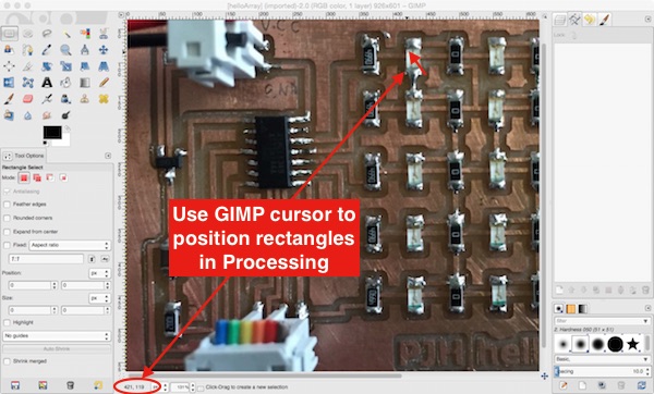
I used GIMP to get the pixel position of the LEDs on the image so I could place the red rectangles over the LEDs to simulate them flashing.
Video showing the LED array flashing chevrons and sending a character over the serial port which determines which pattern of red rectangles (LEDs) are displayed in the Processing window..
Next challenge
I wanted to make Processessing control the LED array, this is more complicated than it sounds and I needed the considerable help of James Fletcher from Fab Academy 2014 to help me understand the C code and the use of interupts. In my basic understanding of the C code the serial pin is waiting for a character and when it reads a character it breakes out of the main loop and runs the interrupt code and then goes back to the main loop.
            //
//
// hello.array.44.c
//
// Charlieplex LED array hello-world
//
// Neil Gershenfeld
// 11/13/10
//
// (c) Massachusetts Institute of Technology 2010
// This work may be reproduced, modified, distributed,
// performed, and displayed for any purpose. Copyright is
// retained and must be preserved. The work is provided
// as is; no warranty is provided, and users accept all
// liability.
//
// Philip Hemsted
// 04/20/15
// Amend code to make array flash chevrons
//
// Philip Hemsted
// 05/11/15
// Amend code to add serial port for Processing application
//
// Philip Hemsted
// 05/13/15
// Update to enable serial comms to board with interupt
//

#include
#include
#include

#define output(directions,pin) (directions |= pin) // set port direction for output
#define input(directions,pin) (directions &= (~pin)) // set port direction for input
#define set(port,pin) (port |= pin) // set port pin
#define clear(port,pin) (port &= (~pin)) // clear port pin
#define pin_test(pins,pin) (pins & pin) // test for port pin
#define bit_test(byte,bit) (byte & (1 << bit)) // test for bit set

#define bit_delay_time 102 // bit delay for 9600 with overhead
#define bit_delay() _delay_us(bit_delay_time) // RS232 bit delay
#define half_bit_delay() _delay_us(bit_delay_time/2) // RS232 half bit delay
#define char_delay() _delay_ms(10) // char delay

#define serial_port PORTA
#define serial_direction DDRA
#define serial_pins PINA
#define serial_pin_in (1 << PA6)
#define serial_pin_out (1 << PA6)
#define serial_interrupt (1 << PCIE0)
#define serial_interrupt_pin (1 << PCINT6)


#define led_delay() _delay_ms(1) // LED delay

#define led_port PORTA
#define led_direction DDRA

#define A (1 << PA1) // row 1
#define B (1 << PA2) // row 2
#define C (1 << PA3) // row 3
#define D (1 << PA4) // row 4
#define E (1 << PA5) // row 5


volatile char anim = '0';


void get_char(volatile unsigned char *pins, unsigned char pin, char *rxbyte) {
    //
    // read character into rxbyte on pins pin
    //    assumes line driver (inverts bits)
    //
    *rxbyte = 0;


    //
    // delay to middle of first data bit
    //
    half_bit_delay();
    bit_delay();
    //
    // unrolled loop to read data bits
    //
    if pin_test(*pins,pin)
        *rxbyte |= (1 << 0);
    else
        *rxbyte |= (0 << 0);
    bit_delay();
    if pin_test(*pins,pin)
        *rxbyte |= (1 << 1);
    else
        *rxbyte |= (0 << 1);
    bit_delay();
    if pin_test(*pins,pin)
        *rxbyte |= (1 << 2);
    else
        *rxbyte |= (0 << 2);
    bit_delay();
    if pin_test(*pins,pin)
        *rxbyte |= (1 << 3);
    else
        *rxbyte |= (0 << 3);
    bit_delay();
    if pin_test(*pins,pin)
        *rxbyte |= (1 << 4);
    else
        *rxbyte |= (0 << 4);
    bit_delay();
    if pin_test(*pins,pin)
        *rxbyte |= (1 << 5);
    else
        *rxbyte |= (0 << 5);
    bit_delay();
    if pin_test(*pins,pin)
        *rxbyte |= (1 << 6);
    else
        *rxbyte |= (0 << 6);
    bit_delay();
    if pin_test(*pins,pin)
        *rxbyte |= (1 << 7);
    else
        *rxbyte |= (0 << 7);
    //
    // wait for stop bit
    //
    bit_delay();
    half_bit_delay();
}


void put_char(volatile unsigned char *port, unsigned char pin, char txchar) {
    //
    // send character in txchar on port pin
    //    assumes line driver (inverts bits)
    //
    // start bit
    //
    clear(*port,pin);
    bit_delay();
    //
    // unrolled loop to write data bits
    //
    if bit_test(txchar,0)
        set(*port,pin);
    else
        clear(*port,pin);
    bit_delay();
    if bit_test(txchar,1)
        set(*port,pin);
    else
        clear(*port,pin);
    bit_delay();
    if bit_test(txchar,2)
        set(*port,pin);
    else
        clear(*port,pin);
    bit_delay();
    if bit_test(txchar,3)
        set(*port,pin);
    else
        clear(*port,pin);
    bit_delay();
    if bit_test(txchar,4)
        set(*port,pin);
    else
        clear(*port,pin);
    bit_delay();
    if bit_test(txchar,5)
        set(*port,pin);
    else
        clear(*port,pin);
    bit_delay();
    if bit_test(txchar,6)
        set(*port,pin);
    else
        clear(*port,pin);
    bit_delay();
    if bit_test(txchar,7)
        set(*port,pin);
    else
        clear(*port,pin);
    bit_delay();
    //
    // stop bit
    //
    set(*port,pin);
    bit_delay();
    //
    // char delay
    //
    bit_delay();
}

ISR(PCINT0_vect) {
    //
    // pin change interrupt handler
    //
    static char chr;

    if(!pin_test(serial_pins, serial_pin_in)) {
        get_char(&serial_pins, serial_pin_in, &chr);
        if(chr != 10)
            anim = chr;
    }

}


void flash(uint8_t from, uint8_t to, uint8_t delay) {
   //
   // source from, sink to, flash
   //
   static uint8_t i;
   set(led_port,from);
   clear(led_port,to);
   output(led_direction,from);
   output(led_direction,to);
   for (i = 0; i < delay; ++i)
       led_delay();
   input(led_direction,from);
   input(led_direction,to);
   }

void led_cycle1(uint8_t number, uint8_t delay) {
   //
   // cycle through LEDs
   //
   uint8_t i;
   for (i = 0; i < number; ++i) {
      flash(B,A,delay);
      //flash(C,A,delay);
      //flash(D,A,delay);
      //flash(E,A,delay);
      //flash(A,B,delay);
      flash(C,B,delay);
      //flash(D,B,delay);
      //flash(E,B,delay);
      //flash(A,C,delay);
      //flash(B,C,delay);
      flash(D,C,delay);
      //flash(E,C,delay);
      //flash(A,D,delay);
      flash(B,D,delay);
      //flash(C,D,delay);
      //flash(E,D,delay);
      flash(A,E,delay);
      //flash(B,E,delay);
      //flash(C,E,delay);
      //flash(D,E,delay);
      // each LED has a two letter name, in this way you can address each
      // LED by flashing its letter code
      }
   }
void led_cycle2(uint8_t number, uint8_t delay) {
    //
    // cycle through LEDs
    //
    uint8_t i;
    for (i = 0; i < number; ++i) {
        //flash(B,A,delay);
        flash(C,A,delay);
        //flash(D,A,delay);
        //flash(E,A,delay);
        //flash(A,B,delay);
        //flash(C,B,delay);
        flash(D,B,delay);
        //flash(E,B,delay);
        //flash(A,C,delay);
        //flash(B,C,delay);
        //flash(D,C,delay);
        flash(E,C,delay);
        //flash(A,D,delay);
        //flash(B,D,delay);
        flash(C,D,delay);
        //flash(E,D,delay);
        //flash(A,E,delay);
        flash(B,E,delay);
        //flash(C,E,delay);
        //flash(D,E,delay);
    }
}
void led_cycle3(uint8_t number, uint8_t delay) {
    //
    // cycle through LEDs
    //
    uint8_t i;
    for (i = 0; i < number; ++i) {
        //flash(B,A,delay);
        //flash(C,A,delay);
        flash(D,A,delay);
        //flash(E,A,delay);
        //flash(A,B,delay);
        //flash(C,B,delay);
        //flash(D,B,delay);
        flash(E,B,delay);
        flash(A,C,delay);
        //flash(B,C,delay);
        //flash(D,C,delay);
        //flash(E,C,delay);
        //flash(A,D,delay);
        //flash(B,D,delay);
        //flash(C,D,delay);
        flash(E,D,delay);
        //flash(A,E,delay);
        //flash(B,E,delay);
        flash(C,E,delay);
        //flash(D,E,delay);
    }
}
void led_cycle4(uint8_t number, uint8_t delay) {
    //
    // cycle through LEDs
    //
    uint8_t i;
    for (i = 0; i < number; ++i) {
        //flash(B,A,delay);
        //flash(C,A,delay);
        //flash(D,A,delay);
        flash(E,A,delay);
        flash(A,B,delay);
        //flash(C,B,delay);
        //flash(D,B,delay);
        //flash(E,B,delay);
        //flash(A,C,delay);
        flash(B,C,delay);
        //flash(D,C,delay);
        //flash(E,C,delay);
        flash(A,D,delay);
        //flash(B,D,delay);
        //flash(C,D,delay);
        //flash(E,D,delay);
        //flash(A,E,delay);
        //flash(B,E,delay);
        //flash(C,E,delay);
        flash(D,E,delay);
    }
}


int main(void) {
   //
   // set clock divider to /1
   //
   CLKPR = (1 << CLKPCE);
   CLKPR = (0 << CLKPS3) | (0 << CLKPS2) | (0 << CLKPS1) | (0 << CLKPS0);
   //
   // initialize output pins
   //
   //set(serial_port, serial_pin_out);
   //output(serial_direction, serial_pin_out);
   //
   // set up pin change interrupt on input pin
   //

   set(GIMSK, serial_interrupt);
   set (PCMSK0, serial_interrupt_pin);
   sei();

   //
   // main loop
   //
   while (1) {

       //static char chr;
       //get_char(&serial_pins, serial_pin_in, &chr);
       //char_delay();


       switch(anim) {
           default:
            case '0':
               //led_cycle4(10,5);
            break;

            case '1':
               led_cycle1(10,5);
            break;

            case '2':
               led_cycle2(10,5);
               break;

           case '3':
               led_cycle3(10,5);
               break;

           case '4':
               led_cycle4(10,5);
               break;
       }

       _delay_ms(1);


   }
   }
Lessons learnt
I found Processing straightforward to use with a familiar user interface. Also building the code up in simple blocks makes it easier to develop an overall application.
Downloadable design and program files
hello.array.44.c
Processing sketch LED_array_1