


W4 ¦ Electronics production
Assignment for week 4
- Make the FabISP in-circuit programmer
- Mill the board
- Solder the components on the board
- Set it up for programming
- Link to this week’s home work page
What is the FabISP?
The FabISP is an in-system programmer for AVR microcontrollers, designed for production within a FabLab. It allows you to program the microcontrollers on other boards you make.
But what is an AVR microcontroller?
An AVR microcontroller is a type of device manufactured by Atmel.
Ok but what is a microcontroller?
A microcontroller is a single chip with build in features so it can run on its own, a mini computer. It sort of acts like the microprocessor on the motherboard of your PC but it does not need the motherboard or any other components to run. It is a lot simpler than PC microprocessor and deals with data in 8-bit chunks as its data bus is 8-bit wide.
An 8-bit microcontroller like the AVR doesn’t usually have an operating system, although it could run a simple one if required, instead it just runs a single program. Loading this program into the AVR is done with an AVR programmer or another microcontroller that is already programmed using a USB cable and 6-pin IDC to 6-pin IDC cable. Most simple machine like washing machines use a microcontroller.
Click here for further basic info on microcontrollers and this article MICROCONTROLLERS: THE BASICS by Tom Igoe explains it well.
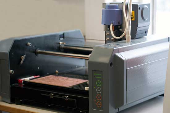
Milling the Board:
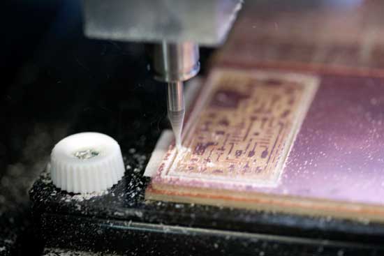
We will be milling the board using a precision desktop milling machine the Roland Modela MDX-20.
STEP 1 - Preparing the milling machine:
- Turn the machine on.
- Fasten your board with the special double tape provided. NO dust underneath.
- Make sure you have a sacrificial layer of material under your board. It will protect the machine and the milling bit when it cuts all the way through.
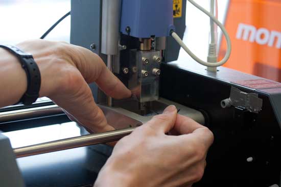
- Set the correct milling bit in. First we use 1/64". Make sure its almost all in so it does not accidentally break when we move to the zero point. Use an allen key to fasten it. Careful not to over tighten. (The bits and the tools are on a magnet on the machine)
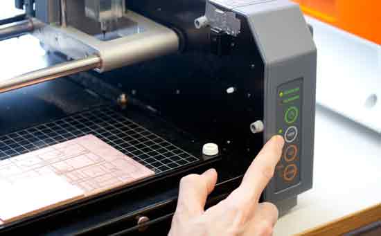
- Move the machine to the zero point pressing VIEW button.
- Use the DOWN button to set the machine in the lowest position, then take it back up a notch. (the purpose if moving the machine head up after putting it all the way down is to allow for it to move down from the starting position to cut into the material and it gives the milling bit the space it needs to travel above the board when moving from one milling position to the next.)
- Now lower your bit with the allen key so it sits on the board. Fasten it carefully. (Note you might need to go first to step 8 if your board if far from the zero point.
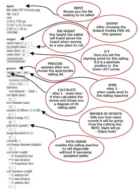
- Next open the Fabmodules and from there set your starting point. Zero point is an absolute position in the lower left corner. You need to play with the X and Y values to find where you want to start.
- If for some reason you need to reset the milling machine, say to clear its memory of a job it did not finish. Press and hold in both arrow keys at the same time. Pressing up and down to clear the cach in the machine only works in view-mode (light next to view button turned on)
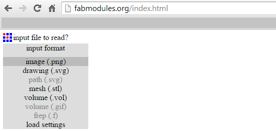
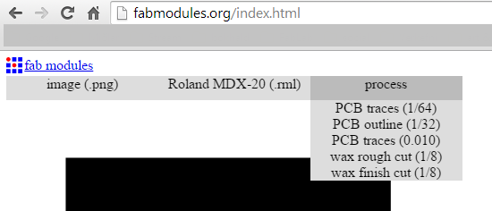
STEP 2 - Preparing the file on the computer with FabModules
- Download the board files.

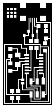
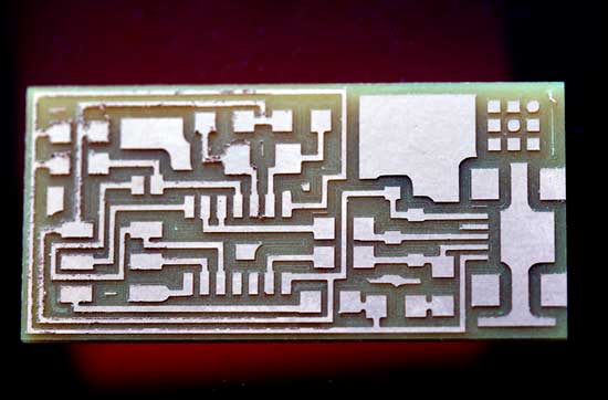
 There are two files needed for the milling. One for the traces (the boards roadmap) and one for the cutting outline. The reason why it is in two files is that two different milling bits are required for each job. We need a small flat 1/64" bit for the traces. For cutting the outline we need 1/32" end mill (flat). The third one is to show the placement of the components.
 - Use the FabModules to communicate with the Milling machine.
- INPUT: Start by importing the image you are about to mill. First is the trace.png
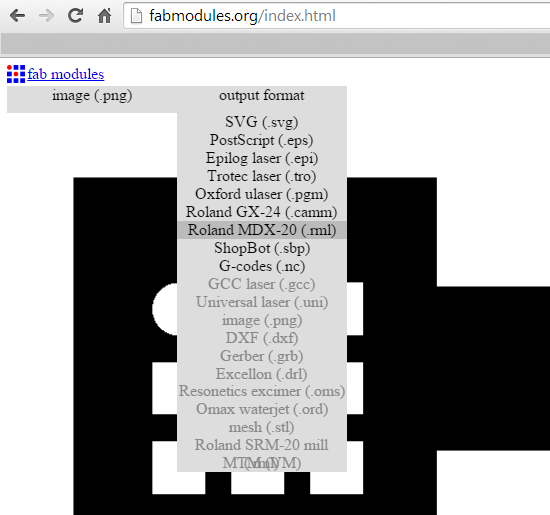
- OUTPUT: Choose the machine you will use. We choose Roland Modela MDX-20
- PROCESS: Pick the milling bit. - For milling the traces we need 1/64"
- Set the starting point. Zero point is an absolute position in the lower left corner. You need to play with the X and Y values to find where you starting point is.
- Press CALCULATE to see if the milling path is ok
- NUMBER OF OFFSETS -tells you how many rounds it will be going from the cutting line. NOTE: black will go - (black-hole). Make sure your paths don't overlap.
- Press SEND when ready and you're done!


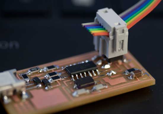
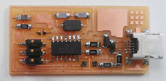
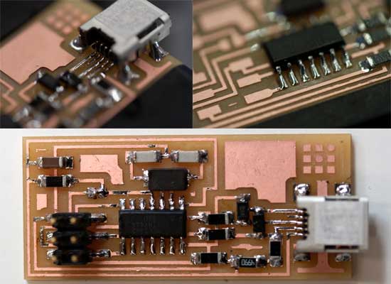
Solder the components on the board
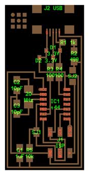
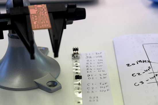
To see what what components are needed and where they are supposed to go we need the FabISP board diagram. Solder the components to the board using a soldering iron and solder. Use the handy copper wire to desolder.


We need the following components for the board:
| 1. | 1 USB connector |
J2 USB is the mini USB header. Solder the mini USB header first. |
| 2. | 1 ATTiny 44 microcontroller | Solder the microcontroller second. NOTE: There is a little circle on the chip that should be facing to the top left or on the rounded end in Neil's diagram. |
| 3. | 1 Capacitor 1uF |
Components marked with a "C" on the diagram. Capacitors have no marking on them, be careful not to mix them up. NOTE: capacitors do not have polarity, orientation does not matter. |
| 4. | 2 Capacitor 10 pF | |
| 5. | 2 Resistor 100 ohm | NOTE: resistors do not have polarity, orientation does not matter. |
| 6. | 1 Resistor 499 ohm | |
| 7. | 1 Resistor 1K ohm | |
| 8. | 1 Resistor 10K | |
| 9. | One 6 pin header | The components marked J1 ISP is the 6 pin programming header.
Orientation does not matter. |
| 10. | 2 jumpers - 0 ohm resistors | The components marked SJ1 and SJ2 are solder jumpers. -SJ1 can be bridged with solder. -Put a 0 ohm resistor over SJ2 on this board |
| 11. | 1 Cystal 20MHz | NOTE: crystals do not have polarity, orientation does not matter. |
| 12. | two Zener Diode 3.3 V | Diodes have polarity the "C" or cathode -end is marked with a tiny line.
Place the side with the line on it over the "C" side pad in the diagram.
You may need a magnifing glass. |
| 13. | one usb mini cable | |
| 14. | one ribbon cable | |
| 15. | two 6 pin connectors |
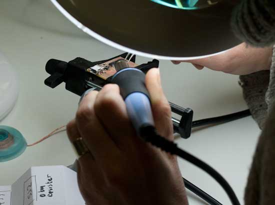
Soldering
- First step before we start soldering we need to clean all the debris on the edges. Just use your fingers or tweezers.
- It is really handy to put the board in a clamp to hold it in place. Another nice trick is to keep all your tiny components on a sticky tape fastened to your components list.
- The best temperature for soldering circuits is to have the soldering iron around 260C. So in our case we kept it between red and orange. I found the soldering not too difficult, I guess that years of silver soldering helped.
- After finishing soldering I did a continuity test and the board worked fine. So next was to move to the programming.
Set the board up for programming
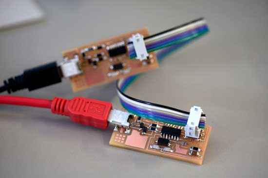
To be able to program the microcontroller we need to set a starting program on the chip. That allows us to communicate with it. That can be done with a AVR programmer which can be bought off the shelf but it can also be done with another FABISP which has been programmed already.
I followed the programming instruction given on the tutorial page. I use windows 8.1 and I had some issues with the compiler. Somethings still remain to be worked on. I finished the programming by using another computer.
- When making the cable make sure that the two 6 pin connectors face the same way on the wire. The two 6 pin connectors has two ridges on one side and that should always face microcontroller.
- . NOTE: When connecting two boards together.that the same color wire needs to go on the same pin on both boards.
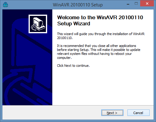
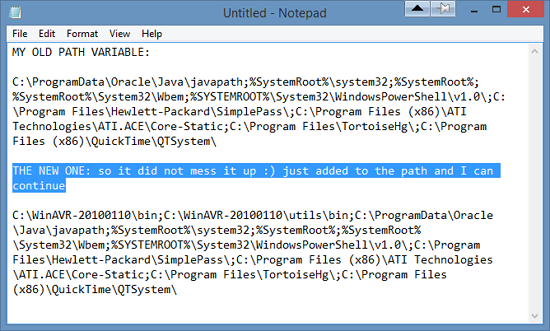
- Next step: Download and install the necessary software for your operating system and download the firmware. I followed the instructions and got the WinAVR compiler. I copied the systems path variable on my computer before setting up the WinAVR compiler. Apparently the WinAVR is no longer supported and it can destroy that part. (hmmm took some googling to understand the computer language but I got there.)
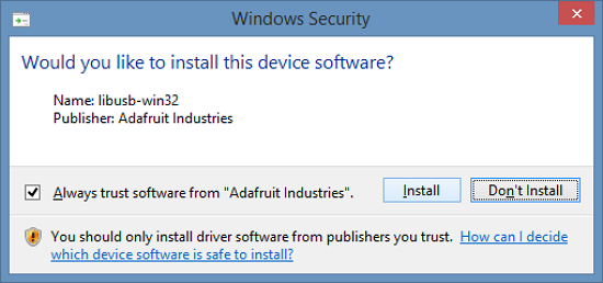
- Next was to download the drivers necessary for my version of Windows and download the FabISP Firmware. All went well.
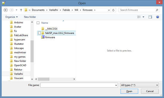
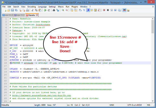
- Then I needed to edit the Makefile. The Makefile is in the firmware directory that I downloaded. I didn't find the file at first. It was disguised as a file for MAC. The Makefile is set up to work with the AVRISP2 by default. If you are using another programmer, you will need to edit the Makefile.
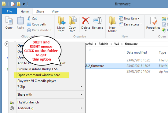
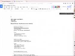
- In the process I learn this trick: to open the command window in the correct folder SHIFT - right mouse click and you get this option.
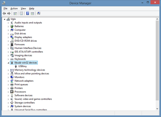
- My computer recognized the new board
- But when I tried to do the commands needed to program it. Like Make clean, it would not work on my Windows 8.1 PC . So I just moved to a friends computer and finished the process there. All went well.