


W6 ¦ Electronics Design
Assignment for week 6
- Redraw the echo hello-world board
- Add (at least) a button and LED (with current-limiting resistor)
- Check the design rules, and make it
- Link to this week’s home work page
The board
This is the Hello World board we are making this week:


Drawing the Board
- To draw the board we downloaded Eagle.
- Import a parts library from the FabAcademy schedule page for this week : fab.lbr
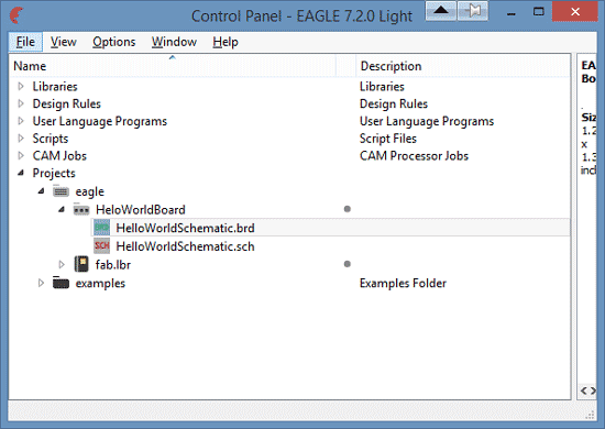
- To place the library in Eagle save the link to the folder Eagle makes under MyDocuments. It will then show up in the PROJECT folder under EAGLE
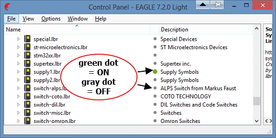
- To make things simpler hide all the libraries not in use. Right click on the LIBRARIES folder and choose USE NONE. In this case we will using the SUPPLY.LBR so make that active by making the dot green. The FAB.LBR should also be green.
- Next make a New Project under the PROJECT folder. Name your project. Then right mouse click your new project and select NEW- SCHEMATIC to start drawing.
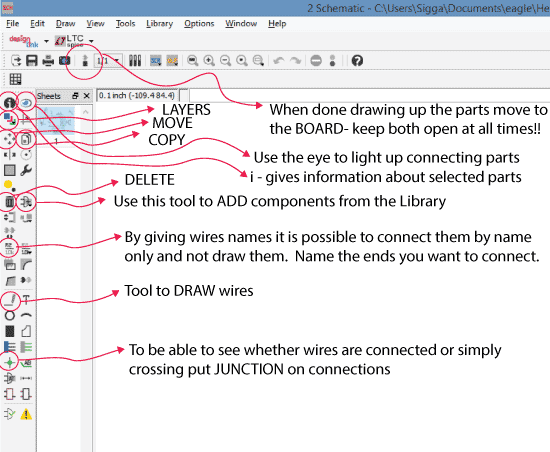
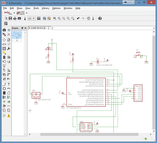
- The schematic toolbar:
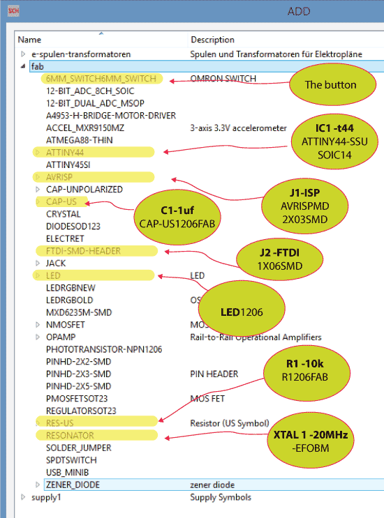
- I placed the necessary parts for the board and added a button and an LED with an resistor in the schematic.
- The schematic drawn up.
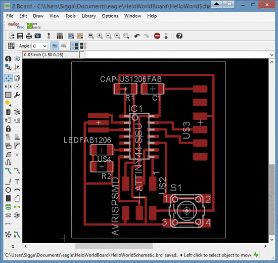
- When finished in schematics move to BOARD to draw the traces.
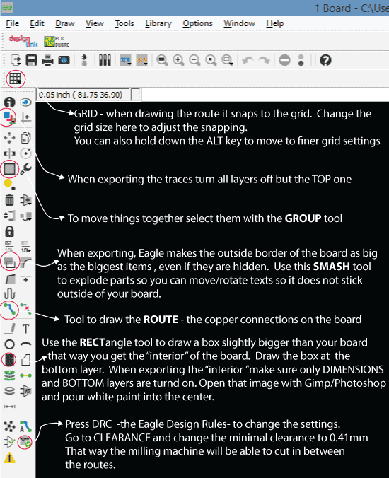
- To change the Design Rules - press the DCR button low in the toolbar. You need to change clearance to o.41mm to be sure the Milling Machine will be able to cut between the routes
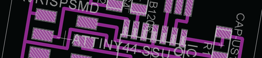
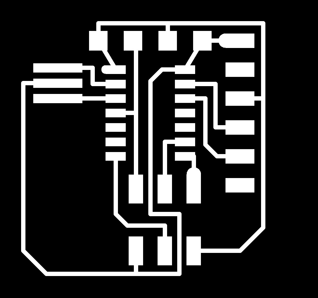
- The Board drawn up.
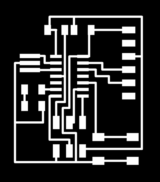
- Next step is to export the traces
Milling and making the board
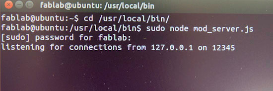
- To get the milling machine and the FabModules to talk together in Ubuntu we need to type:
- Milling was pretty straight forward.
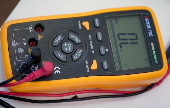
- There are only two components where the orientation matters. The microcontroller and the LED. The microcontroller has a dot on its back indicating that it should connect to the VCC. The LED we can test with a Multimeter
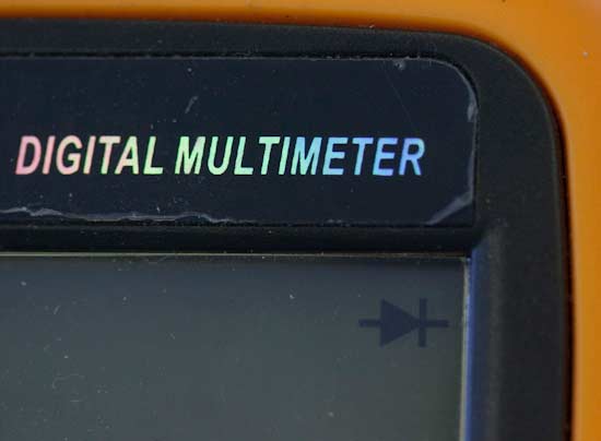
- On a multimeter the black lead is the negative and the red positive. Press the center button till you get this arrow symbol in the right hand corner of the screen.
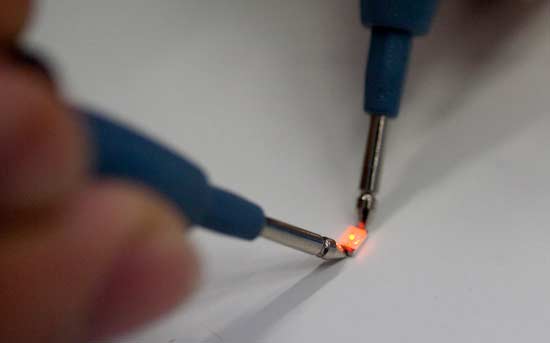
- When the LED lights up you know that the end where the black lead is touching is the minus - therefore that end should be connected to ground/GND.
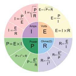
- When calculating what size of resistor we need we use Ohm's law: I = V/R.
- I stand for current in units of amperes (A).
- V is the potential difference measured across the conductor in units of volts
- R is the resistance of the conductor in units of ohms.
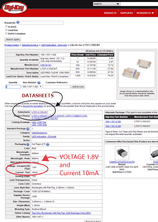
- To be able to calculate the resitor for the LED we need to find the data sheet for that LED. We find a link to the LED in the FabAcademy weekly schedule, week 6.
- Our calculation looks like this:
- We start by changing the mA into amps = 0.01A.
- We know that we will be taking in 5V so we find the difference 5V-1.8V=3.2V
- 3.2V/ 0.01A= 320 Ω
- we need 32o Ohms or higher for the resistor, so we take 499.
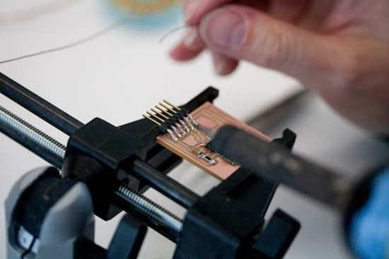
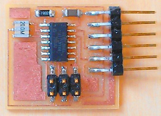
- Soldering the parts
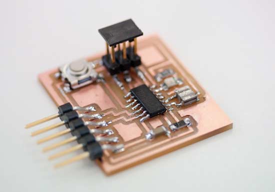
- Hello World Board finished