


W3 ¦ Computer-Controlled Cutting
Assignment for week 3
- Design, make, and document a press-fit construction kit
- Get familiar with parametric design tools
- Learn how to use the laser cutter and the vinyl cutter
- Use cardboard!
- The press-fit construction kit should make up more than one form
- Link to this week’s home work page
Rapid prototyping with the laser cutter- Design brief
For this project I wanted to make a press fit construction kit that would help in the presentation of food. Think big parties, weddings, buffets, restaurants and caterers.

I know from an experience when hosting large parties that space on the food table is often limited so I wanted to design something that would utilize the space above the table. Raising the food from the table would also work to present the food in a nice way.
I imagined that the final outcome could be perhaps be made out of see through material like clear plastic or glass. I also considered water cut ceramic tiles with the legs being made out of wood. I also do find the material Corian® exiting option.
One very important design requirement for me was that the construction kit would take as little space as possible when not in use. So basically lego for the dining table.
Inspiration
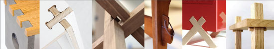
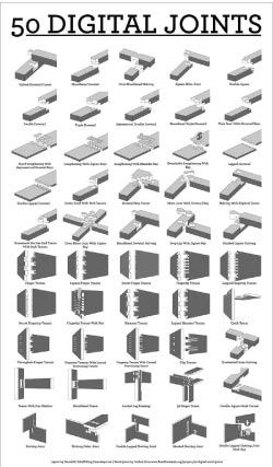
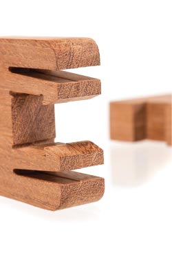
I started my research by looking into joinery. I have for a long time had a soft spot joinery, my heart skips a beat when I see for beautifully crafted joinery. So I had a little look at that and collected my research on Pintrest.
Computer work
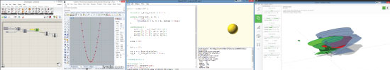
Next step was looking at ways to design the thing. I looked at the program FlatFab which is very cool to work with. I believe that I will return to that one at a later point for my own students. Next I looked at OpenSCAD, that was way too complicated for me who does not have any programming background. I also made a honest attempt with my class to get Antimony up and running on the computers at the lab, but we failed after a very frustrating afternoon.
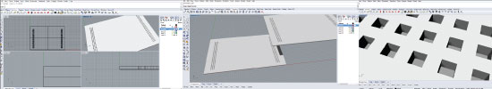
I started working in both Rhino and SkechUp and quickly found out that I liked the Rhino better. Then I wanted to learn to work with the Grasshopper adon for Rhino. I found a very good course on Lynda.com where I have access through my work: Up and Running with Grasshopper with Chris Reilly. Excellent course, but half way through it I panicked at the complexity and my own lack in math.
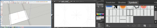
I made a conscious decision that if I wanted any thing made this week I would have to start working on the laser and the best way for my to get any design done was to work within Illustrator. I found a way to make it work in parametric manner by using symbols. I will how ever return to Grasshopper since I find that very exciting way to work.
Rapid prototyping - Working in the lab
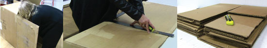
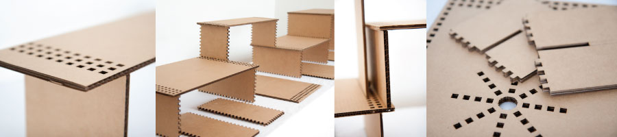
Step One: Find a cardboard box and cut it up to 30x60cm to fit in the machine.
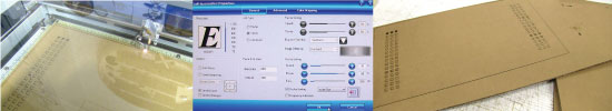
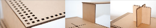
Step two: Send the first design onto the lasercutter. I went with a simple first design with very basic interlocking since I was looking for something aesthetically pleasing. Then it was time to play with them and see where that would lead me.
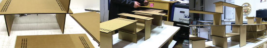
After the first mockup of three pieces I realized that my design would work better if the holes would be on the edge of the plate. That way I could more easily connect more plates to it, not only upwards but also to the sides. So it took me two design attempts to place them where they would work best.
This lead me to make sides with jagged edges all around. Thinking it would be a good idea if the sides could be utilize as a plate when not in there regular use. But the edges made the design very busy so I took I step back and decided on straight side edges.
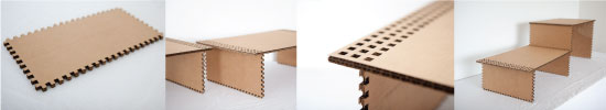
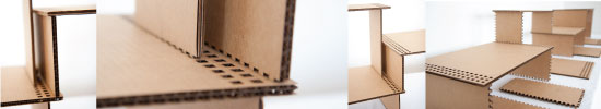
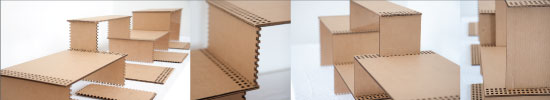
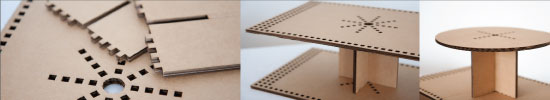
After playing a lot with the pieces they started to come more and more tattered and unstable. I wondered if this kind of joinery would be stable enough so I started working on designing some kind of supporting structure. After few brain farts I came up with a solution that was both minimal and made the whole structure a lot more stable.
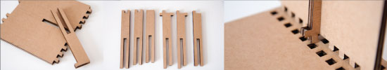
I started to look at ways to make some kind of base or feet. First design look awful!
The next one was more minimal and I felt that it would work.
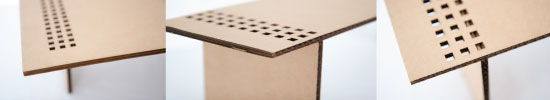
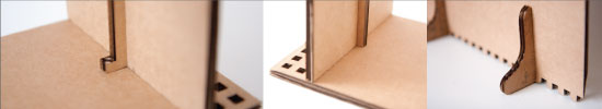
After playing with it I wondered if one should also be able to connect the plates in the sideway direction. That led to single line of holes running along the long side of the plate. I also thought to make a slot in the smaller side-plates to connect them together and put them to dual use as I support a plate from the center of the main plate.
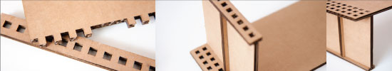
First I only put in a single cross in the middle of the plate. but after playing with it I wanted to be able to stack more than one on top of each other. That led to the star shape in the middle.
This opend up the possibility to also work with circles shapes.
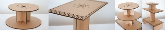
Some combinations were more pleasing to the eye that others to say the least. Some look very strange.
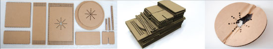
At the end of this playful process, which I really enjoyed, I ended up with some kind of press fit kit that would consist of 10 different designs. But to get there it took many attempts and I made over 40 different design in the whole. ( I actually got told off for using too much cardboard…. ) I also want to include the failure of the burning circle, simply forgot to turn the air on. Lesson learned!
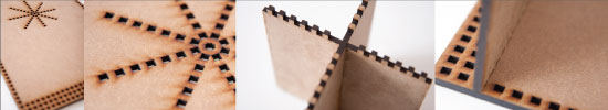
At the end of the day I was really curious to see how this would work in a harder material so I made one attempt with MDF. That was challenging since I had to rethink all the sizing not only the slots but also the spacing. It all had to work out with different numbers. So Grasshopper here I come….
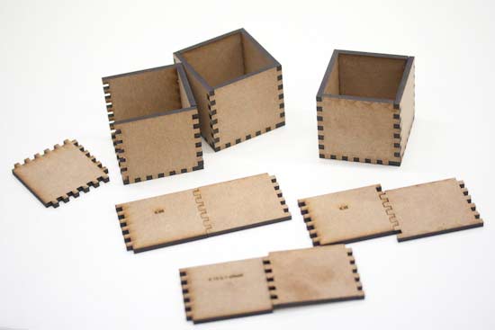
Since the laser burns away certain amount of material when working it is necessary make up for that, especially if things are supposed to fit snugly together. So when working with press fit, an offset of 0.1 mm is often recommended. That is, make a stroke of 0.2 mm, then “expand”/”stroke to path” that stroke again. Then reverting it back to 0.01 mm outline/stroke and delete the extra lines (for holes: delete the outer lines, for the outline: delete the inner line since we are making up for material loss). Both Illustrator´s and Inkscape´s strokes works in the same way, that is the stroke expands around the midline. This means that 0.2mm ends up as 0.1mm offset. Working with MDF I found that 0,2 mm outline did not work. It turned out as an impossible smash fit. I made few tests and found out that for 4 mm thick MDF a outline of 0.15 or 0.17 worked the best for me.