


W13 ¦ Networking and Communications
Assignment for week 13
- Design and build a wired &/or wireless network connecting at least two processors
- Link to this week’s homeworkpage
Making the boards
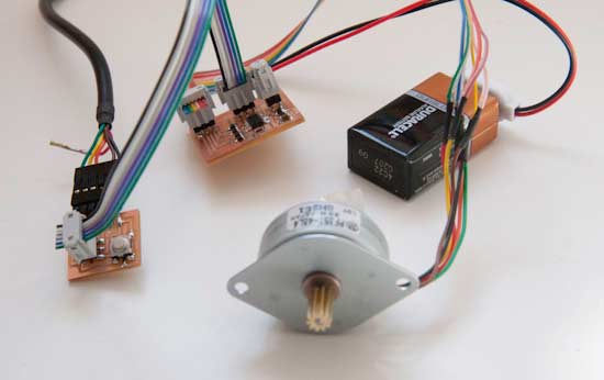
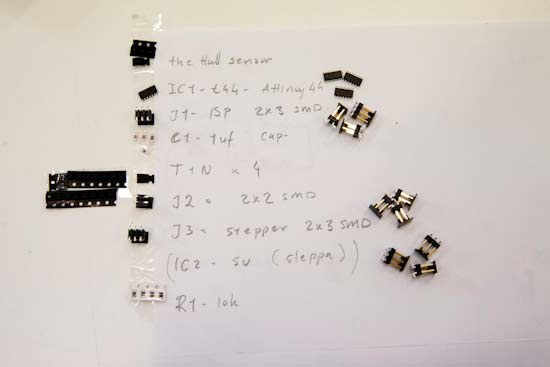
I am using this week to prepare for my final project. There I will need 30 motors and 30 boards to control them. I need to be able to give each board a command to move the motor to a new specific location. I am continuing with the board from OutPut week where I used I Hall sensor and a Stepper Motor. This week I made some alteration to the design so they could all be connected together.
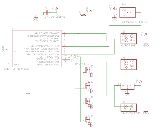
- I began by drawing up the schematics in Eagle. This time around I will not be placing the regulator on the board but my instructor advised me to keep the layout for that possibility.
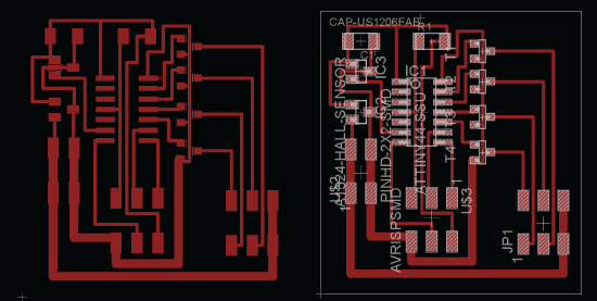
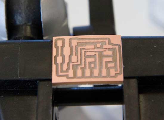
- The board layout.
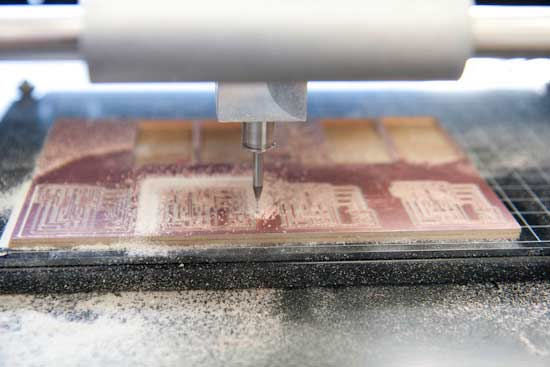
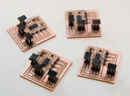
- I milled out 4 boards for the motor and hall sensor board.
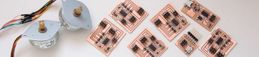
- Gathering all the components together.
- The four board ready.
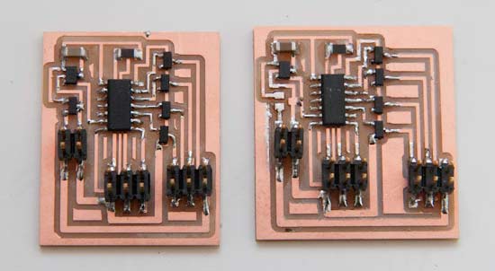
- Here are the two board layouts together. One from last week and one from this week. The main difference is the spacing. Last time I found out that I could not physically fit two connectors on to the board at the same time since the connecting pins were so close together.
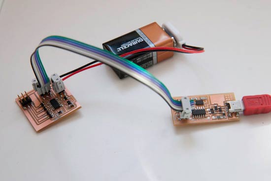
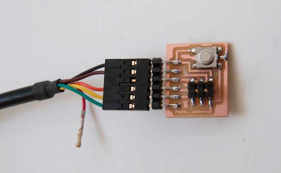
- To be able to connect the board up for serial communication I needed to make a connection board.
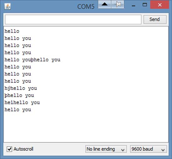
- I had bit of a trouble communicating with the board through the serial port. We then found out that I needed to disconnect the red power wire and break the green connections. Then I was able to send commands and get a response back.
Programming
This week I finished watching the C Essential Training with Isac Artzi on Lynda.com. After the frustration in output week I made the decision to program within the Arduino environment.
- Programming the board with the FabISP.
- All wired up for communication. For this week I am using the Sofrware Serial library in Arduino. That allows for communication between the boards This library uses the Serial protocol RS-232. Further information on the Serial Data Standards can be found here. Later in week 14 I had to change to a new Serial library as this one did not facilitate multiple nodes all connected in a daisy-chain. The library that I later used is called SoftwareSerialWithHalfDuplex.
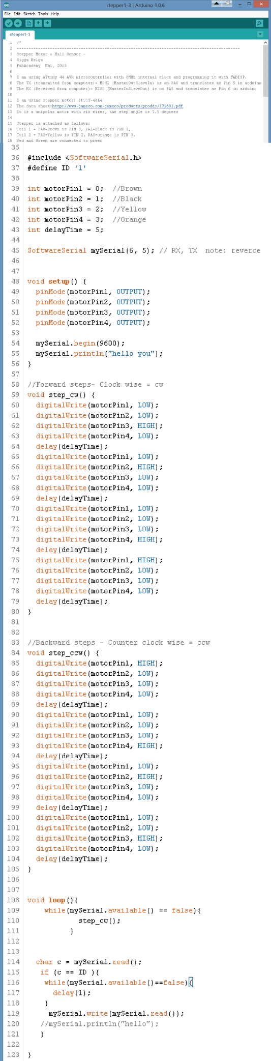
- Here is my program that allowed me to communicate with my board. Still early days but at least we are talking. Download: Stepper
In week 14 I got the code to work a lot better, and there I use the other Serial library mentioned above. Here is a link to that code. - Space control for major Tom...