


W18 ¦ Project Development
Assignment for week 18
- complete your final project, tracking your progress:
- what tasks have been completed, and what tasks remain?
- what has worked? what hasn't?
- what questions need to be resolved?
- what will happen when?
- what have you learned?
- documentation during development
- demand- vs supply-side time management
- spiral development
- Link to this week’s homeworkpage
Final project development
For my final project I am continuing with the idea of the poetry machine. I have been using all the week's assingments from week ten to prepair for the final project. So in week 15 I explain in details what I am aiming to achive and how the machine is supposed to work. But to summon it up in few words it should work like this:
- I have many microcontrollers all connected together listening in in the same line waiting for an order.
- Each mircocontroller controls one motor, and it has it's own ID.
- On a website there is motion detection through a web cam
- when motion is detected it sends a random poem from a pool of poems down the communication line
- On a web server there is a node.js bridge that allows for communication between the website and the microcontrollers
- When the microcontroller detects it's ID it will react on the order that follows. And is basically a certain position for the motor.
Motors and surprises
I had ordered 35 motors from Jamico.com. On their website and in the datasheet it was stated that the motors were bipolar. When they arrived they turned out to be unipolar.
While I was waiting for the motors to arrive I had already prepaired and made 2 boards with H- bridge motor controllers.
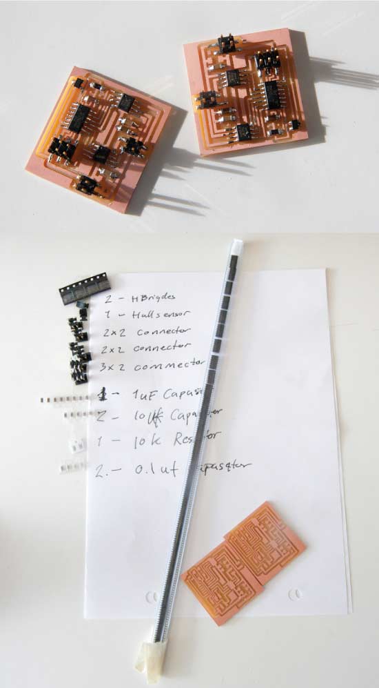
I had expected to work with bipolar motors and there for I had ordered 70 H-Bridge motor controllers from DigiKey that only work with bipolar motors. Another slight setback was the size of the motors. The motors turned out to be a lot smaller than I had anticipated. Their diameter is 20 mm. I had seen this is the data sheet but not quite realized these were literally baby motors.
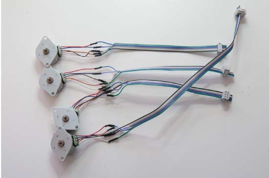
I was surely dissapointed but I prepaired and rewired 4 of the motors to work with. In output week I had already made 4 boards to talk to unipolar motors. So it was back working with them.
Experimenting with motion
I began using the motors and tried out some of the ideas I had in mind for the poetry machine. I had been working on my motor code for the past few weeks. For these experiments I used a code written in the Arduino environment.
I tried having the motors turn a string of pearls. It kinda worked but not very well. The motors could only turn the pearls if they got a push at the begining but they could not start on their own. I used Illustrator to draw up the mechanics and laser cut it in MDF.
This was heartbreaking to me as I has so sincerely wanted this to work. The motor also got extremly hot, so in desperation I pushed them aside and desided I needed some other motors.
/*
==============================================================================================
Stepper Motor & Hall Sensor -
Sigga Helga
FabAcademy  Mai, 2015

I am using ATtiny 44 AVR microcontroller with 8MHz internal clock and programming it with FABISP.
The TX (transmited from computer)= MOSI (MasterOutSlaveIn) is on PA6 and translates as Pin 5 in arduino
The RX (Received from computer)= MISO (MasterInSlaveOut) is on PA5 and translates as Pin 6 in arduino

I am using Stepper motor
The data sheet: www.jameco.com/Jameco/Products/ProdDS/2158557.pdf
It is a unipolar motor with five wires, the step angle is 7.5 degrees

Stepper is attached as follows:
Coil 1 = PAO=White is PIN 0, PA1=red is PIN 1,
Coil 2 = PA2=blue is PIN 2, PA3=orange is PIN 3,
Brown is connected to power and to both coils

This program controls one motor.  I have many motors connected and I am talking to many microcontroller all listening in on the same line
I am sending 2 bites of info, first is the ID of the motor, second is the new location.
When the microcontoller reconizes it's ID it acts on the order, otherwise it ignors it.

==============================================================================================
*/
#include
#define ID 2
#define stepsPerPosition 12              //if the motor has 7,5 degree steps that means 360/7,5 = 48 and each "step_cw" function consists of 4 steps hence 48/4 =12 for full circle
#define totalPositions 40                //How many letters are on the wheel.
#define myHomePosition 1

int motorPin1 = 0;
int motorPin2 = 1;
int motorPin3 = 2;
int motorPin4 = 3;
#define delayTime 5

int hallSensorPin = A7;                  //Hall Sensor reads magnetic field.  Using this to find the "home" position

int myCurrentPosition = myHomePosition;  // position 0 does not excist....0;
int myTargetPosition = 0;                // position 0 does not excist....0


SoftwareSerialWithHalfDuplex mySerial(6, 5, false, false); // RX, TX  for reciving and transmitting data

//=====================SETUP======================================================================

void setup() {
  pinMode(motorPin1, OUTPUT);
  pinMode(motorPin2, OUTPUT);
  pinMode(motorPin3, OUTPUT);
  pinMode(motorPin4, OUTPUT);
  pinMode(hallSensorPin, INPUT);

  mySerial.begin(9600);
  mySerial.println("hello you");                 // debug line - prints "hello You" each time you reset the program


}


//====================MAIN LOOP====================================================================

void loop(){                                         //If my target position is Zero(a position that only exists at the beging of the program) then
  if (myTargetPosition ==0) {                        // find the home position, the loop is defined here below.
      findHomePosition();                            // when you have found the home position set the target postion to one
      myTargetPosition=1;
  }
    if(mySerial.available() >= 2 ){                  // if 2 bytes or more arrived through the seraial communication line
            int targetID = mySerial.read();          // write down the value you read from mySerial and put it into a int called targetID
            int newTargetPosition = mySerial.read(); // write down the second value your read from mySerial into to a int called newTargetPosition
            if (targetID == ID ){                    // If the ID is the same as my ID
              myTargetPosition = newTargetPosition;  // then make the new target postion as my Target position
              }
     }


      if (myCurrentPosition != myTargetPosition){      // if my current Position is not the target position
         moveOnePositionCW();                          // keep moving until you have reached it.
      }
 }

//==================DEFINING FUNCTIONS=============================================================


void whichDirectionToGo (){                          // Shall we go backwards or forwards?
 if (myTargetPosition > myCurrentPosition) {         // If the target number is higher that my current number
    moveOnePositionCW;                               // move forward
  }

  else if (myTargetPosition < myCurrentPosition) {    // if he target number is lower that my current number
    moveOnePositionCCW;}                              // move backwards
}


void moveOnePositionCW (){ //clockwise direction      // one move in clockwise direction
    myCurrentPosition++;                              // add one to my current position
    if (myCurrentPosition == totalPositions+1)        // if I am one over myTotalPositions (the counting for totalPositions starts at zero hence the plus 1.
        {myCurrentPosition = 1;
        }
    for (int i = 0; i < stepsPerPosition; i++) {      //each "step_cw" consist of 4 steps, so if the motor has 7,5 degree steps that means 360/7,5 = 48 and 48/4 =12
          step_cw();                                  // go forward
        }
}

void moveOnePositionCCW(){                            //counterClockWise direction
    myCurrentPosition--;                              // subtract one from my current position
    if (myCurrentPosition == 0 )                      // if I am one over zero or myTotalPositios (-1)I reset the counter to start counting again
        {myCurrentPosition = totalPositions;
            }
    for (int i = 0; i < stepsPerPosition; i++) {      //each "step_ccw" consist of 4 steps, so if the motor has 7,5 degree steps that means 360/7,5 = 48 and 48/4 =12
          step_ccw();                                 //go backwards
        }
}


void findHomePosition() {                                           //finds the starting point on the wheel using a hall sensor and a magnet.  This runs when the program is started and it then knows where it is
     int hallSensorValue = analogRead(hallSensorPin);               //Read the anlog pin and put the value in an int called hallSensorValue
     while ((hallSensorValue > 450) && (hallSensorValue < 550)) {   //The hall sensor measures around 500-510 when it is neutral but it goes above or belove that when it senses the magnet, so if neutral
       moveOnePositionCW();                                         // keep moving
       delay (1);
       hallSensorValue = analogRead(hallSensorPin);                  //read the hall sensor again
   // while (1){                                                     //Debugger line- sends the Hall Sensor's reading to the console window
         mySerial.write(hallSensorValue);


     }
    myCurrentPosition = myHomePosition;                              //when the magnet is located then that is the home position

}
/*
//Forward steps- Clock wise = cw          //each go forward step consists of 4 steps, 7.5 degrees x 4 = 30 degrees in one step
void step_cw() {
  digitalWrite(motorPin1, LOW);
  digitalWrite(motorPin2, LOW);
  digitalWrite(motorPin3, HIGH);
  digitalWrite(motorPin4, LOW);
  delay(delayTime);
  digitalWrite(motorPin1, LOW);
  digitalWrite(motorPin2, HIGH);
  digitalWrite(motorPin3, LOW);
  digitalWrite(motorPin4, LOW);
  delay(delayTime);
  digitalWrite(motorPin1, LOW);
  digitalWrite(motorPin2, LOW);
  digitalWrite(motorPin3, LOW);
  digitalWrite(motorPin4, HIGH);
  delay(delayTime);
  digitalWrite(motorPin1, HIGH);
  digitalWrite(motorPin2, LOW);
  digitalWrite(motorPin3, LOW);
  digitalWrite(motorPin4, LOW);
  delay(delayTime);
}

*/
//Forward steps- Clock wise = cw          //This loops makes sure the electricity is low on the pin that was previoulsy high.
void step_cw() {
  digitalWrite(motorPin1, LOW);
  digitalWrite(motorPin2, LOW);
  digitalWrite(motorPin3, LOW);
  digitalWrite(motorPin4, LOW);
  digitalWrite(motorPin3, HIGH);
  delay(delayTime);
  digitalWrite(motorPin3, LOW);
  digitalWrite(motorPin2, HIGH);
  delay(delayTime);
  digitalWrite(motorPin2, LOW);
  digitalWrite(motorPin4, HIGH);
  delay(delayTime);
  digitalWrite(motorPin4, LOW);
  digitalWrite(motorPin1, HIGH);
  delay(delayTime);
  digitalWrite(motorPin1, LOW);
}

//Backward steps - Counter clock wise = ccw
void step_ccw() {
  digitalWrite(motorPin1, HIGH);
  digitalWrite(motorPin2, LOW);
  digitalWrite(motorPin3, LOW);
  digitalWrite(motorPin4, LOW);
  delay(delayTime);
  digitalWrite(motorPin1, LOW);
  digitalWrite(motorPin2, LOW);
  digitalWrite(motorPin3, LOW);
  digitalWrite(motorPin4, HIGH);
  delay(delayTime);
  digitalWrite(motorPin1, LOW);
  digitalWrite(motorPin2, HIGH);
  digitalWrite(motorPin3, LOW);
  digitalWrite(motorPin4, LOW);
  delay(delayTime);
  digitalWrite(motorPin1, LOW);
  digitalWrite(motorPin2, LOW);
  digitalWrite(motorPin3, HIGH);
  digitalWrite(motorPin4, LOW);
  delay(delayTime);
}
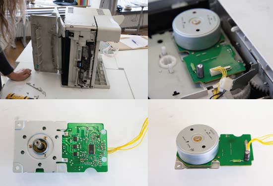
Recycled motors
I spent a long day calling companies here in Iceland and considering ordering some new motors from the States or UK. In the end I could not afford it, since the cost was over US $600. I then decided to to try out recycled motors. So I went to the electronics recycling center, which is a workplace for teenagers that have for some reason dropped out of school. There I was very welcome. They sent me home with all sorts of household appliances to test out. I knew that my best changes to get a hold of some stepper motors were inside printers and copiers.
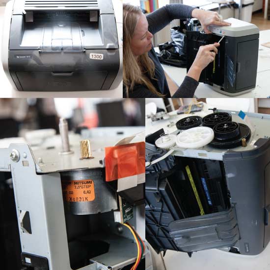
From HP laser printer I salvaged an excellent stepper motor. It was 6.4 ohm and after some fiddeling with my code I got the motor to work. It had extremely good tork. But it overheated my H-bridges. I managed at one point to explode one of my H-briges, firework and all.(likely I shorted from ground to power when trying to connect to a 13 V adapter)
Our FabAcademy instructor had at this point left us for India for two weeks and even though there were occational video conference calles it did not help me much. I got stuck on this problem for few days. In the end I called a friend how helped me finally crack this thing. One of the keys was OHM's law. To find out how much power could go through the H-bridges it was back to the data sheet. There it said 2 Amper max.
When calculating what power is needed to drive the motors we use Ohm's law: V=I*R
- V (volts), is the potential difference measured across the conductor in units of volts
- I stand for current in units of amperes (A).
- R is the resistance of the conductor in units of ohms.
- We start by mulitplying the max Ampers the H-Bridge can take and the resistance in the motors = 2*6.4 = 12.8 V
- So now we know we need 12.8V to power the motors optimally.
int pulseWidthModulation_count = 30;
unsigned int onDelay = 95;
unsigned int offDelay = 5;  // Do not set to zero

void PulseWidthModulate(int pwmMotorPin1, int pwmMotorPin2)
{
  for (int count = 0; count < pulseWidthModulation_count; ++count) {
    digitalWrite(pwmMotorPin1, HIGH);
    digitalWrite(pwmMotorPin2, HIGH);
    delayMicroseconds(onDelay);
    digitalWrite(pwmMotorPin1, LOW);
    digitalWrite(pwmMotorPin2, LOW);
    delayMicroseconds(offDelay);
  }
}
//Forward steps- //Clock wise = cw
void step_cw() {
  digitalWrite(motorPin1, HIGH);
  digitalWrite(motorPin2, LOW);
  digitalWrite(motorPin3, LOW);
  digitalWrite(motorPin4, LOW);
  PulseWidthModulate(motorPin1, motorPin1);

  digitalWrite(motorPin1, HIGH);
  digitalWrite(motorPin2, LOW);
  digitalWrite(motorPin3, HIGH);
  digitalWrite(motorPin4, LOW);
  PulseWidthModulate(motorPin1, motorPin3);

  digitalWrite(motorPin1, LOW);
  digitalWrite(motorPin2, LOW);
  digitalWrite(motorPin3, HIGH);
  digitalWrite(motorPin4, LOW);
  PulseWidthModulate(motorPin3, motorPin3);

  digitalWrite(motorPin1, LOW);
  digitalWrite(motorPin2, HIGH);
  digitalWrite(motorPin3, HIGH);
  digitalWrite(motorPin4, LOW);
  PulseWidthModulate(motorPin2, motorPin3);

  digitalWrite(motorPin1, LOW);
  digitalWrite(motorPin2, HIGH);
  digitalWrite(motorPin3, LOW);
  digitalWrite(motorPin4, LOW);
  PulseWidthModulate(motorPin2, motorPin2);

  digitalWrite(motorPin1, LOW);
  digitalWrite(motorPin2, HIGH);
  digitalWrite(motorPin3, HIGH);
  digitalWrite(motorPin4, HIGH);
  PulseWidthModulate(motorPin4, motorPin2);

  digitalWrite(motorPin1, LOW);
  digitalWrite(motorPin2, LOW);
  digitalWrite(motorPin3, LOW);
  digitalWrite(motorPin4, HIGH);
  PulseWidthModulate(motorPin4, motorPin4);

  digitalWrite(motorPin1, HIGH);
  digitalWrite(motorPin2, LOW);
  digitalWrite(motorPin3, LOW);
  digitalWrite(motorPin4, HIGH);
  PulseWidthModulate(motorPin1, motorPin4);
}
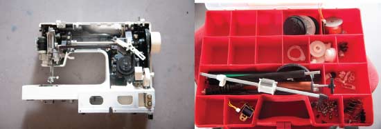
The motor from the copier turned out to be of another sort all together. So it was usless to me. The motor from the sawing machine was a DC motor, so again no use to me.
I went back to the recycling center and they were more than willing to collect all incoming printers for me. They estimated the number of printer to be around 40 a month that went through their hands. Very happy and excited about this news I went ahead and made plans to work with beads and motors. ( I intend to have them collect printers for me through out the summer since I am just starting on the motor journey)
Balls and beads
I had intended to 3D print some forms for my poetry chain and then cast a plaster mold of them to be used for casting ceramics. Unfortunately the 3D printer was out of order so I simply made some simple forms by hand.
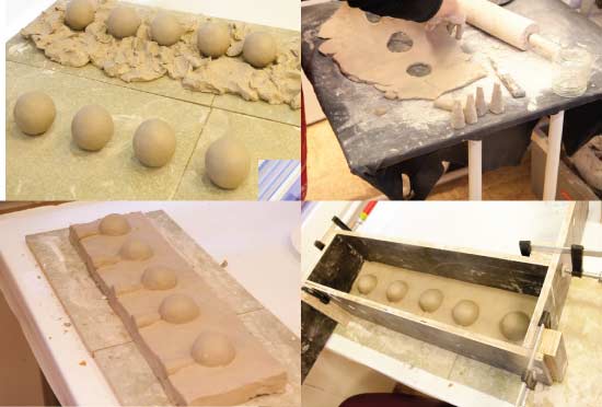
I made 4 molds, two diffrent sizes and room for 5 in each. I used clay to pack around the balls, then I also made pour holes out of clay. After having put a box around it I poured in plaster. After removing the box I pealed the packing clay carefully away and put the half-plaster mold back in a box and poured again. And vola! we have a two sided mold. Normally the drying time for molds of this size are 4-6 weeks but I speed dried them in the kiln for 72 hours at 60°C.
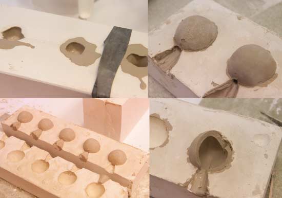
I soon realized that this was maybe a bit ambitious given the time left, only 10 days to go. I was rushing the process too much and opening up the molds before they were ready. This ment I was tearing the balls apart. After casting 20 of them I decided that this process was too slow for me at that point in time simply because I was getting too stressed to enjoy this. Each cast was taking much longer since the molds were not properly dry, so to make couple of chains of 40 balls each would take me 4 days. So I decided on a simpler method. (I still have the molds and have plans to continue with them in the summer.)
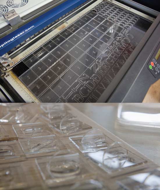
The laser cut stamps intended to be used with the casted ceramic balls.

I very quickly made some smaller solid balls by hand. Put a hole through them and marked the letters by hand. This took me no time at all, and I managed to make 240 of them in couple of hours. I dried them overnight and fired them slowly to 1260°C.
Experimenting further with the mechanics
Having gotten the beads out of the kiln I was eager to make some further experiments. I was really pleased with the outcome of this experiment. The beads where bit on the heavier side, I would much more prefer elegant, fragile, thin and hollow porcelain beads but maby in the future.
When I returned to the recycling center only one printers had come their way that week. It was the same Hp laser printer I had managed to salvage the large motor from. So now I had two of them. But I had always hoped to have more running so it was back to the drawing table.
Back to the motors I had ordered
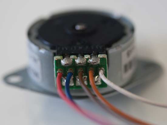
I turned my attention back to the stepper motor I had ordered hoping to be able to convert them from unipolar to bibolar.
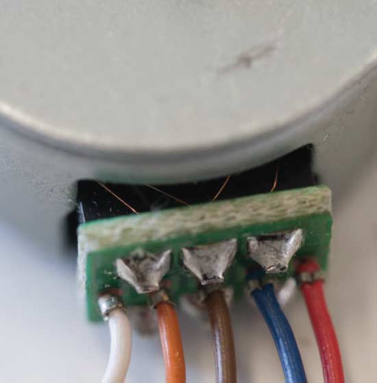
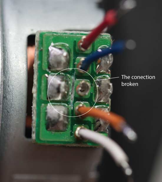
As can be seen from the image above the coils unite in the brown wire.
My first attempt was to drill into the motor where the brown wire was. That did not end well as I manged to kill all connection doing that.
I then realized that the green board were the wires were connected had the key. I measured the motor with multi meter and saw that by cutting through the underlying copper I could break the connection. And that actually worked! That ment that other possibilites opend up. I had high hopes since I had read that bipolar motors had more tork than the unipolar.
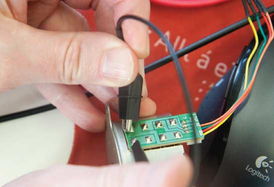
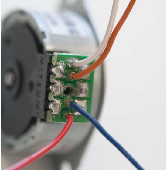
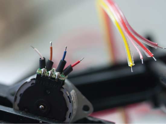
It took me few attempts to find out what was the best way to rewire the motors so I could use them with my boards. The very first one worked well but was messy. Then I simply cut the wires and soldered new flat cable at the end.
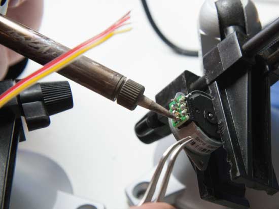 Next I tried the method shown above where I would strip the motor completely of the orginal wires and solder a flat cable straight onto the motor. I would then rearange the wires of the flat cable before putting on the connection shoe. This method I used on six motors with every other failing me. It turned out that the solder would disappear throught the board and make up some unexpeted connections at the backside.
Finally I found this method to work the best. Here I would cut the orginal motor wires back and make the switching of the wires in the flat cable right here. Red and white are on the same coil. So red and red paired up, white and brown, orange and pink and blue and yellow.
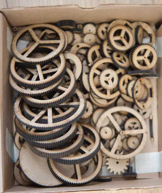
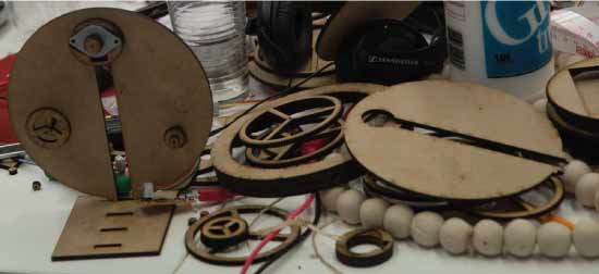
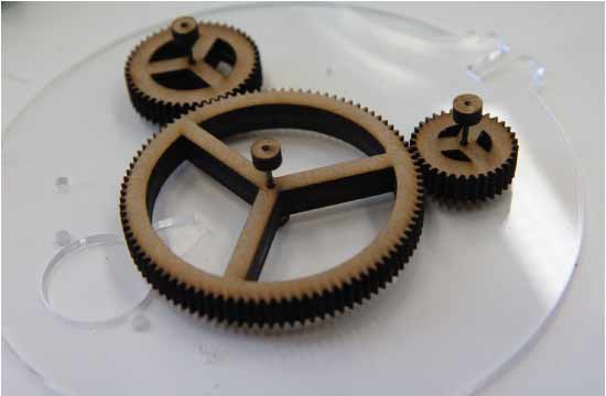
Experimenting with gears and the motors
Having recovered my motors I was excited about the new possibities and started to work with gears. I really enjoyed this process and thruth be told I lost count at how many design attempts I made during these days. Following are few of the highligts and stepping stones in the design process.
I used Illustrator to draw up the designs but for the gears I found a free addon for Inkscape called gear-developer. So I would use that tool to draw the gears but then copy them over to Illustrator to work further with them.
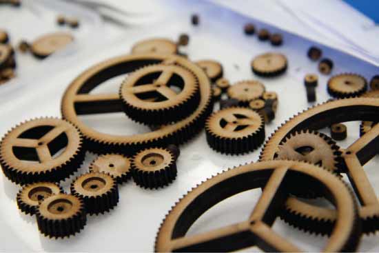
I used the laser cutter for these experiments. I mainly worked with MDF but also used clear plexy further on. In the begining I did not realize how much the laser cuts down at an angel, leaving the edge slighly tapered. This really came to hunt me in the end.
I quickly found out that motors were still really weak. With the pulse width modulation code I could now drive them at their maximum power, 25V and 2 Ampers, without them boiling over to motor heaven. They were working a lot better than before, but still crap.
With this construction above I made some further experiments with my code and managed to make everthing work like expected. That is the microcontroller would would listen in and react when it recived it's ID from the bridge. And the motor moved to it's new position.
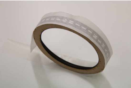
I used the vinyl cutter to make the letters for the wheel.
I used a stencil font and kept both the letters and the vinyl around the letters to be able later to use that part as a stencil and paint the letter straight on to the wheel.
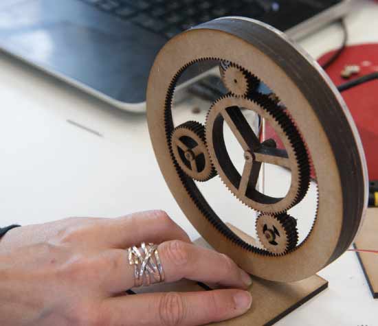
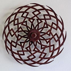
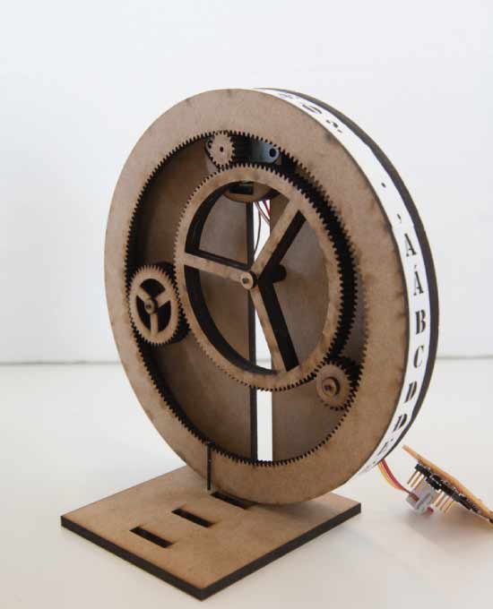
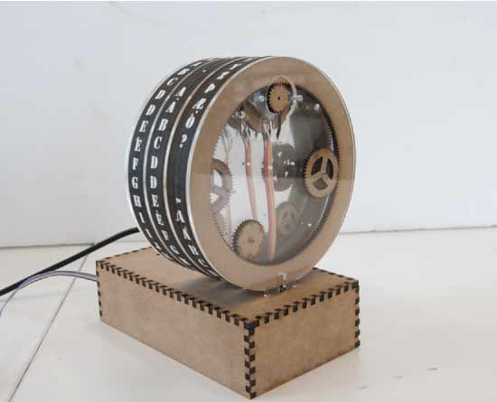
After playing around with the mechanics and the gears I found it real shame to lock that away inside the machine. So I desided to make the sides out of clear plexy glass. That opened up a new way of playing with the gears and the way they looked together in harmony.
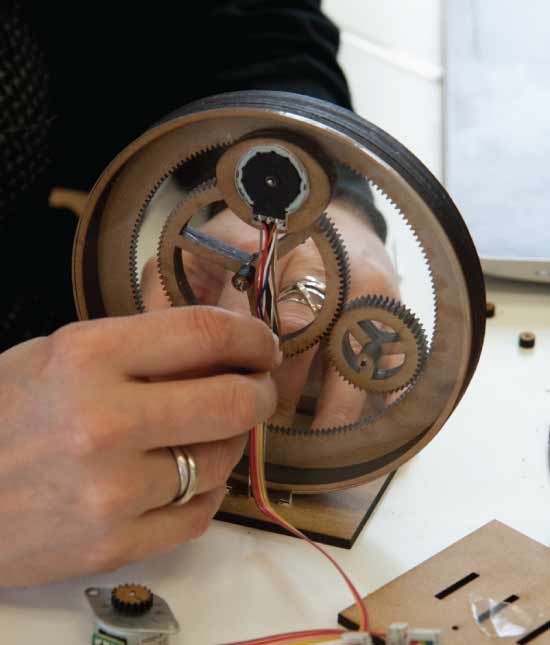
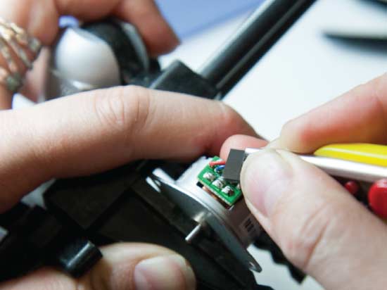
Like I mention above when telling about the motors the messy wiring of the motors was now not appropriate since it was supposed to be seethrough. So I stared to find way to rewire the motors diffrently. That took few attempts before I managed to get it just right.
This wiring for example cost me few days delay as every other motor would end up broken inside the machine. Here the flat cable is soldered directly onto the motor, but the soldering leaked partly underneath the motorboard and coused me so much headache. This connection also broke very easily.
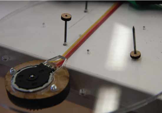
I tried many diffrent designs. My main problems were that the motors where so weak that they had problem starting if the mechanics were not extremely loose and relaxed. Here above in the picture I am using a tool that allows me to screw bolts directly into the plexy with out the use of nuts. That way I could secure the motors better.
After many experiments I felt confident enough to continue and started making mulible version of the one design that worked resonably well. A lot of other ideas came alive during this process, one thing led to another. I ended up redesinging and redefining the main structure many times over during this process.
I tried out a lot of ways to fasten the gears. I was really conscious of all drag being created inside the unit since the motors where so weak. One method I used quite a lot was making small MDF spacers. They fitted just so and sat tightly on the nails used as axels for the gears. I often would split the MDF so it was only 1.5 mm thick. The gears themselves on the other hand had larger center gap and played freely on their axel.
For most of the design attempts I used identical gears cut out of 4mm MDF glued together. Later I found away to skip this and managed to only work with single sided gear. This meant that the tapered cut from the laser cutter did not affect me as much.
Electronics - making boards with H-Bridges
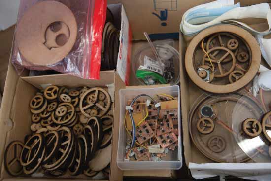
Happy with the progress I was making with the design I went ahead as planed and made 16 new boards with the H-bridges.
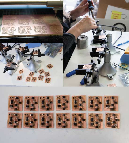
I was both pleased and surprized with the amount of time this process took. 16 boards in 4 hours, 15 min each!
Machine development
At this point I thought I could continue, plain sailing and make the rest of the machine, but no! I ran into many obstacles on the way, and really got stuck on many things but all the problem had one thing in common, the motor weakness. The motors were simply to weak to drive the design. I spent endless hours refining and redesigning.
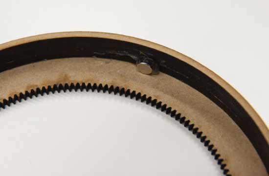
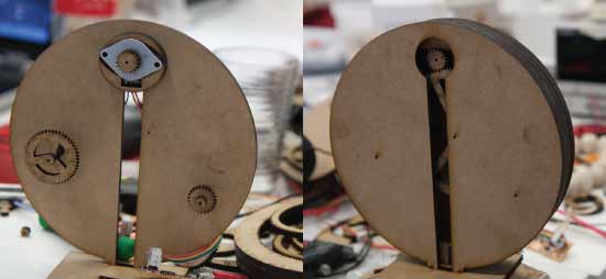
I am using a magnet and a hall sensor to find the home postion. This magnet also caused few problems on it's own. This problem I solved later by enclosing the motor in an MDF casing of it's own. That eliminated most of the drag the magnet was creating but not completely.
This problem I also tried solving by redesigning the whole structure, placing the motor in the center.
Earlier experiments had told me that the motor could not be far from the main wheel. But I honestly don't know what possesed me to spend 6 hours redesigin the whole thing suspecting the whole time it would not work. But hey, you win some and you loose some....
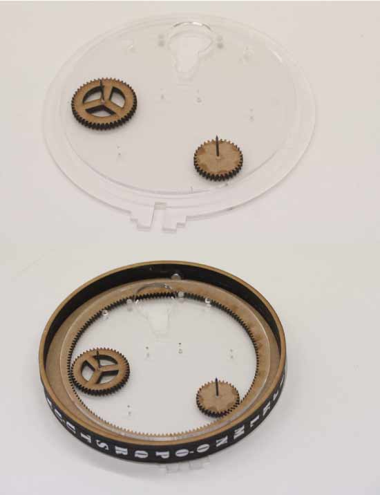
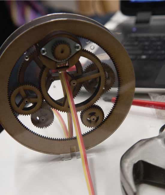
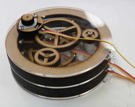
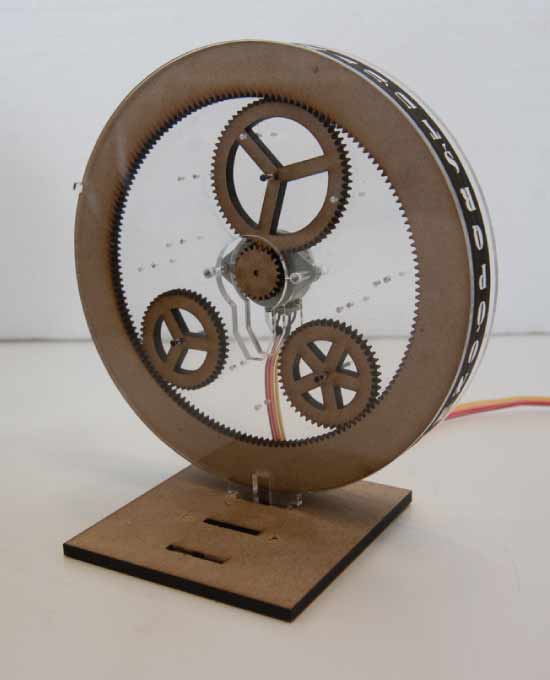
Above is a picture showing how the inside is structured. This was one of the last versions. Here I use two clear plexy plates together for each unit. The smaller plexy workes as a spacer and holds both the gears in perfect placment as well as keeping the bigger wheel also in place. The motor screws straight into the plexy. The bolts used to fasten the motor also work as a spacer and hold the whole thing together.
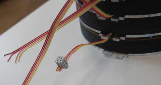
At the bottom of the larger plexy there are feet that go into a box which contains the electronics. The wires need to be thread through the box before the the connection shoes are put on the end.
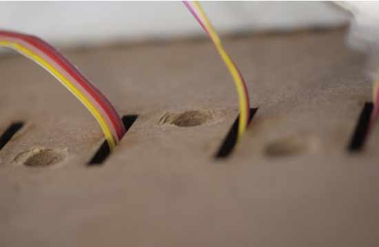
When everything was in place i found that the hall sensor had difficulties reading the the magnet through the MDF. So I drilled some holes in the base right above the hall sensor on each board.
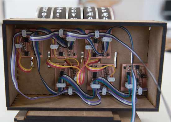
Here is a picture showing under the hood. The motor is thread though the base and connects to it's board. All the microcontrollers are connected together on one line going to the computer. And all the motors are connected together on one power line since the motors need more power than the 5V the microcontroller receives from the computer.
Since I was having such trouble with the motors and their weakness, one of the things i tried and worked ok was to remove the center gear since it sometimes caused unnecessary friction.
In the design attempt that placed the motor in the center I tried to design it so that it did have nice placement of the gears and would be visually pleasing. Like I said before, this design did not work out in the end, but it was visually more complex since there are holes in the plexy which allow for four diffrent placements of the gears. So all stacked together it would look rather busy.
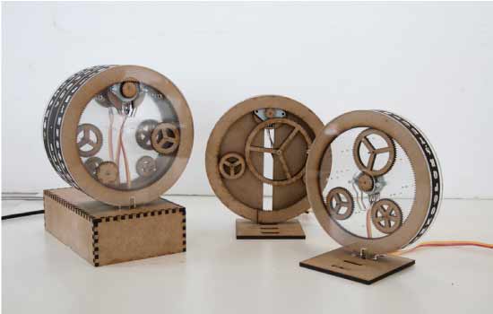
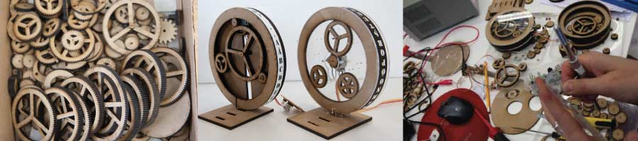
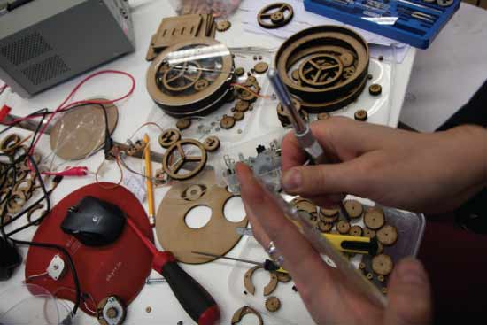
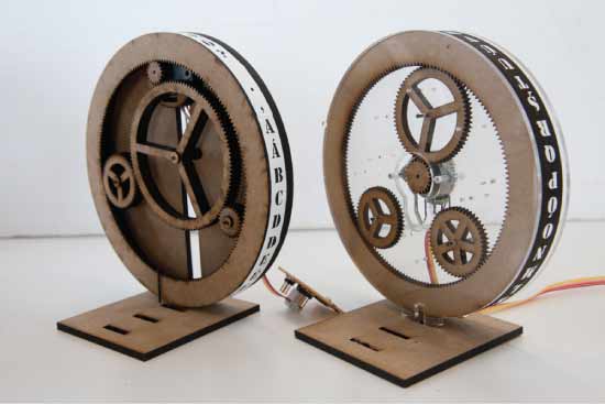
Here is a picture of three of the diffrent designs I made.
I did have lot of fun during this process. I made so many diffrent designs during this experimentation period.