


W8 ¦ Computer-controlled machining
Assignment for week 8
- Make something big!
- Use one sheet of sheet of plywood- 15mm thick,1220 x 2440 mm
- Learn how to work the Big milling Machine -The ShopBot
- Learn how to use VCarvePro
- Link to this week’s home work page
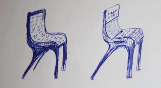
Designing
First step was to come up with some design for this weeks project, make something BIG. After throwing lot of ideas around I decided on a simple chair..or so I thought. I included flexures in the chair design since I was interested in learning more about flexible wood. I have worked a lot with wood and I was curious to see how hinges or flexures would work .To be honest I was rather sceptical it could work well, at least I had difficulty imagining the woods limits and behavior. I therefore wanted to start the design process by doing some testing and get some hands on experience with flexures to get the feel for what was possible and what was not.
Testing
There were three main aims with the testing. First was to learn how detailed I could mill. Second was so learn about the flexibility of the wood. And thirdly I was searching for decorative designs for the wood hinges.
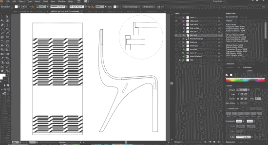
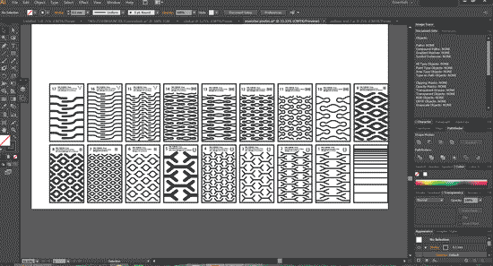
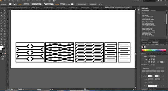
- So with this in mind I began by working in illustrator. Utilizing the Symbol tool as well as the Effect-Transform I managed to work sort of in a parametric way. I set up some patterns I wanted to learn more about. I took some inspiration from the article Curved laser bent wood by in Aaron Porterfield on Instructable. Researching the flexures on the internet I only found documented research relating to 4mm thick wood. When looking into 15mm thickness or greater I only found documentation on very simple straight designs. There were images of work in thicker wood but I could not find any readings. The one thing I learned was that the relationship between the material thickness and the length of the patterns was important.
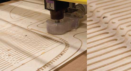
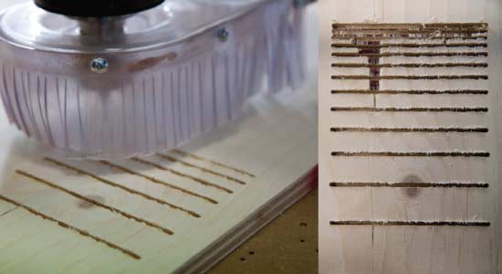
- The first test was a simple line test with 1/8 inch up cutter to see how fine I could cut the poor quality plywood we were working with. The plywood is five layers and it chips very easily. The test showed me that I could not leave less than 3 mm between cuts or it would all disappear.
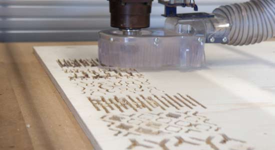
- Since I had learned that the pattern could not be any thinner than 3 mm I altered the tests I had prepared and cut the first 8 test with ⅛ inch up cutter.
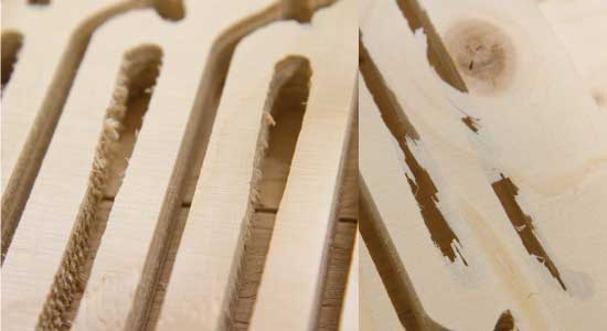
- The result was awful. The wood chipped so much! But I took the test pieces out and started playing with them. I quickly found out that some patterns worked better than others and that I needed a second batch of testing to find out more.
- This time I wanted the test pieces to be wider so I could better explore the correlation between the length of the pattern and the wood thickness. For this second test I designed the patterns so that I could use the ¼ inch tool, because we had a ¼ inch down cutter.
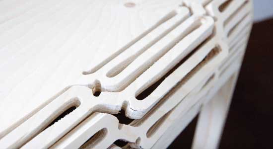
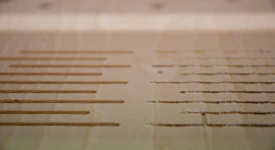
- I started the cutting by using the down cutter for the first 3mm depth. And that made all the difference! the cut was clean and the chipping was almost none. The picture above show clearly the difference. The cuts on the right are made by a 1/8 inc up cutter and the ones on the left are by 1/4 inch down cutter.
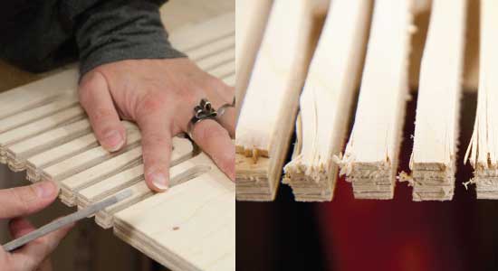
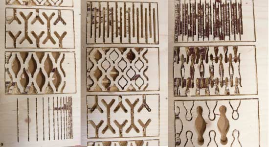
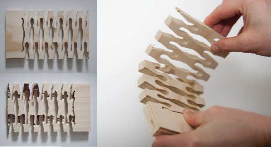
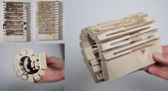
- With these test I wanted to explore the relationship between the width of the gaps and the wood left between. All the test pieces are from 15mm thick plywood and their size is 12cm x 20cm.
- The first test on the left shows ⅛ inch gap made by a up cutter and the wood left between is the same thickness as the gap or 3.175 mm. That piece was the most flexible one but also the most damaged by chipping.
- The second on the left shows ¼ inch wide gap (6.35mm) with the wood left at a 5 mm thickness It was part of the first test batch and was cut with a ⅛ inch up cutter, hence the chipping. That was still very flexible and I would like to repeat that test where I would start with a down cutter.
- The third one is cut with ⅛ inch up cutter and the width is 15mm, same as the thickness. That was not working well except for that it didn't’ chip a lot.
- Test number 4 is cut with ¼ inch tools, first the down cutter and then the up cutter. The width of the wood strips is 14.5mm. That test showed potential but the test piece probably needed to be wider to give the desired flexibility.
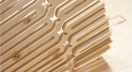
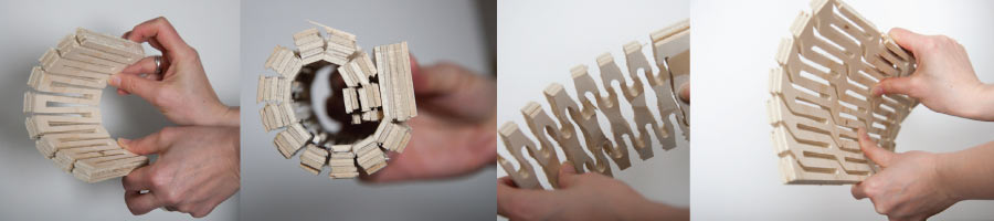
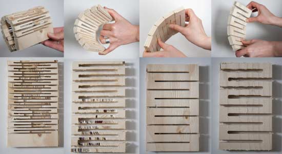
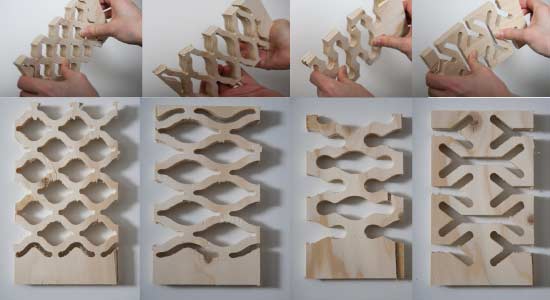
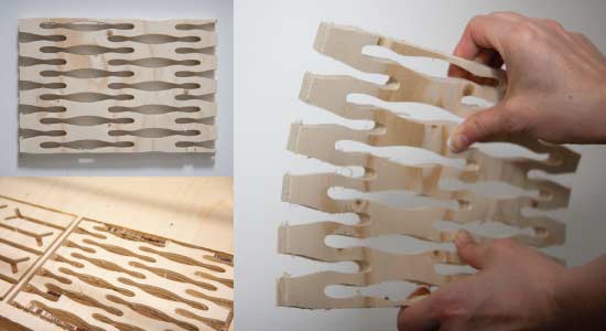
- With the patterns above I discovered that all the test pieces were too narrow in width for them to be flexible. They are the same size as the test above or 12cm x 20cm. The did however showed some potential so I decided to repeat some of them in 30 cm width where the pattern could be longer.
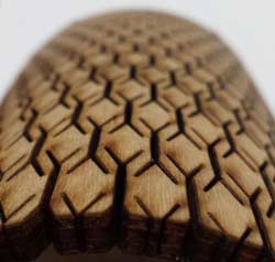
- This pattern here turned out to be the surprize of the testing. It was very flexible, but since it was cut with the ⅛ inch up cutter it was badly damaged. The gaps were around 6mm where they are the narrowest and the narrowest wood strips are just under 4 mm. Here the pattern was finally long enough in relation to the thickness and width of the wood. So from this test I wanted to make a larger 30cm wide version.
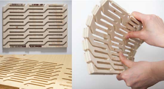
- This test piece is from the second test batch, the size is 30cm x 20cm. I had tested this pattern twice before in the first tests. It was both very rigid and very flexible depending on the pattern size. This attempt was not very successful. The width of the narrowest gap and the narrowest wood strip are 7mm. It did bend a little but not enough. My guess is that the pattern needs to be even longer if I want to keep the wood strips around 7 mm in hope to have the wood sturdy enough to sit on.
- This piece helped me understand a bit more the relationship between the pattern length, the thickness of the wood and the wood strips width. It was obvious to me when playing with this one that the wood strips left behind were way too large. Not only were they 25mm but they were 55mm where the met in the middle of the pattern. This was very rigid and did not bend well.
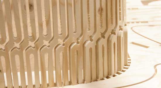
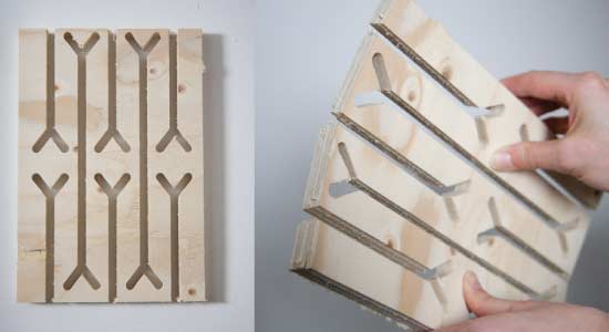
- With this simple pattern I felt I was finally getting somewhere. The test piece was 20 cm x 30m and cut with ¼ inch tools, first the down cutter and then with the up cutter. Note that I forgot to cut the outline of the whole piece with the down cutter. The up cutter chipped badly away at the edges. Here the length of the pattern was allowing for the wood to bend considerably. I found this pattern a bit simple but I decided to develop this pattern further for my chair.
- This simple line test was clearly the winner when it came to flexibility.
Cutting The Chair
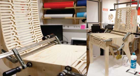
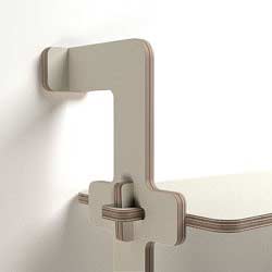
- When preparing the design in VcarvePro I ended up making 10 different cutting paths to get the result I was after. Some cuts were on the line others inside left and others as different depth pockets. I used ¼ inc tools. started the first 3mm with a down cutter for all the lines. I then had it cut to 10 mm depth at the chair sides. I then cut the side bar loose and tested the fit.
- Some of the cuts were very unclean. As the pieces came loose one after the other I needed to keep screwing the plywood plate down in places to keep it flat. Otherwise I would get cuts that were not totally through.
- The ends of the back chipped badly. They needed a lot of filing. Reading up on it I found this brilliant tutorial online about milling bits. There I found out that I need to learn more about Climb vs. Conventional cutting methods.
- After cutting the back loose I tested the fit and decided to widen the gaps I had left in the chair. The back had a lot of splintered ends and it was hard to get them in. I increased the width by 1.5mm and that worked fine in the end.
- The back turned out beautiful and very flexible. I had been most worried that it would not work at all so I was pleased at that point, even though I was still worried about bending it almost 90 degrees.
- Next step was glueing the chair together. I had wanted the design to be minimal and I therefore made the joints not through the sides but only 10 mm in. The glueing went reasonably well. The assembly took about an hour whereas the milling had taken a beginner like me a lot more time.
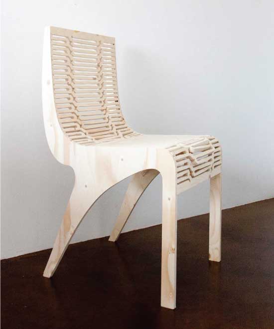
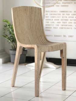
- Well here is the first prototype of the chair. Lot of things remain to be worked on. The pattern needs to be able to bend both ways. I now would like to experiment more with milling the material from both sides as well as milling with a V shaped tools. I have learned a lot from this process and this week has been excellent fun.
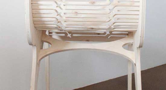
- There were things that I was fairly pleased with in the overall design like the shape of the structure underneath the seat. I was also surprised how sturdy the chair was. I had expected it to be more flimsy.
- As I had anticipated the pattern design of the back would not allow for a 90 degree bend at the front.