


W10 ¦ Input Devices
Assignment for week 10
- Measure something: add a sensor to a microcontroller board that you've designed and read it.
- Link to this week´s homeworks page.
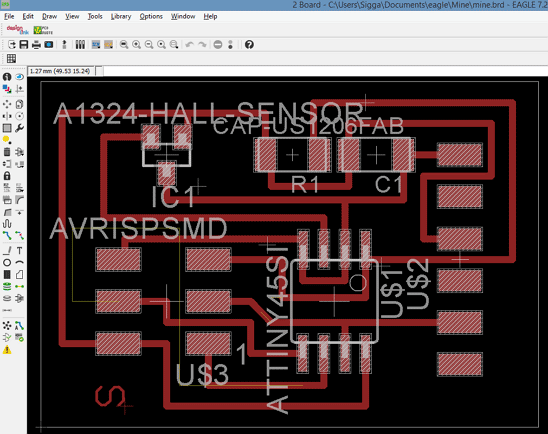
Designing in Eagle
For this week I decided on measuring magnetic field since I could incorporate that into my final project. So Hall sensor is the flavour of the week. To learn more about Hall Sensors here is a link to wikipedia explaining how it works.
The Hall sensor is only partially in the Fab library in Eagle. Only the footprint is there so we need to add and draw the new component. The footprint is in the fab library as a PACKAGE and there we need to create both a symbol and a device so that we can add the component to our schematics drawing.
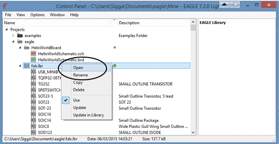
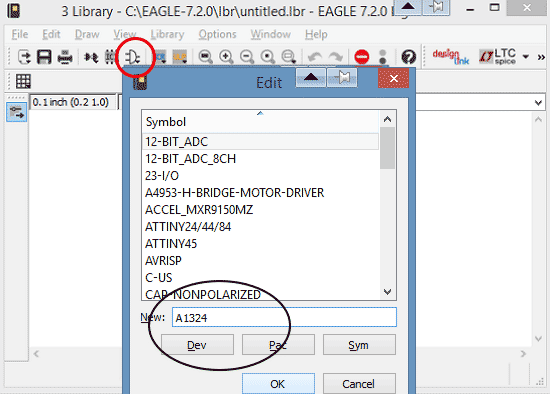
- I opened the Fab library
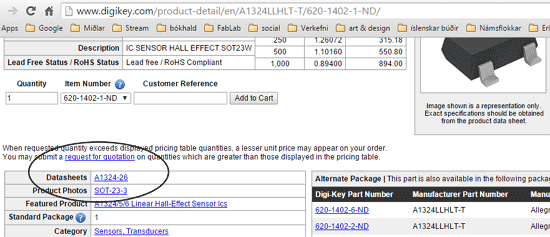
- Then I found the datasheet for the Hall sensor. There I found the names for it or A1324 -26 and SOT-23.
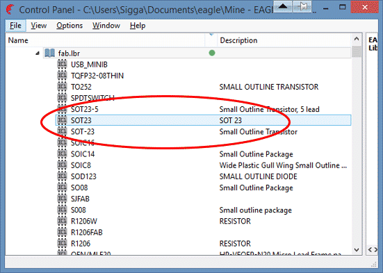
- Knowing the name helped me finding it in the list.
- I opened the footprint in the library - The package.
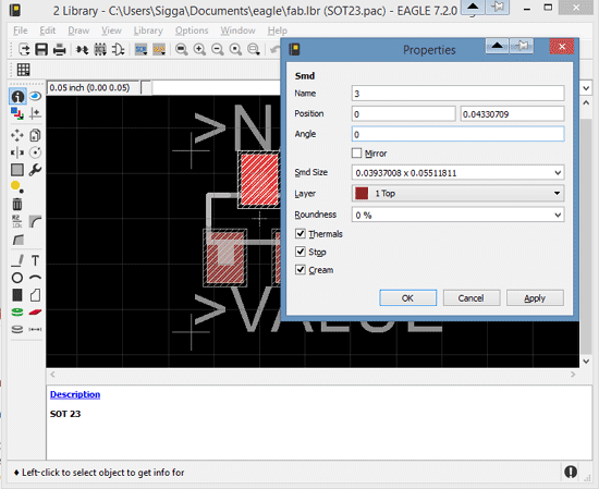
- When inside the SOT23 package the symbol had to be created. I named it A1324 after the information found in the datasheet.
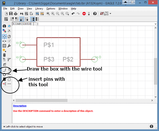
- Next was to draw the symbol using the wire tool. Then I added pins to the symbol with the Pins tool.
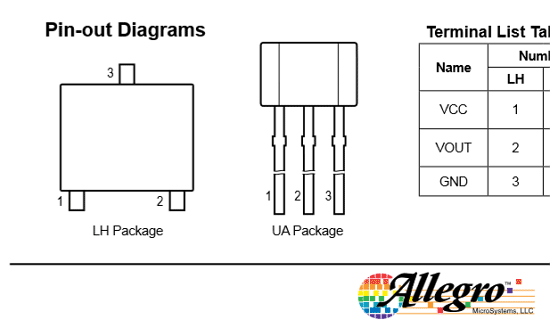
- To be sure how to draw the pins I referred to this drawing in the datasheet.
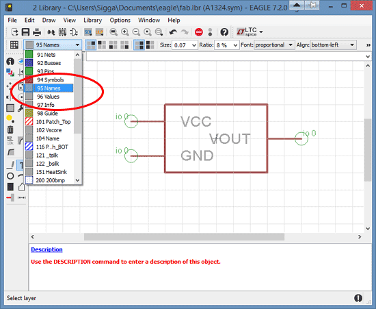
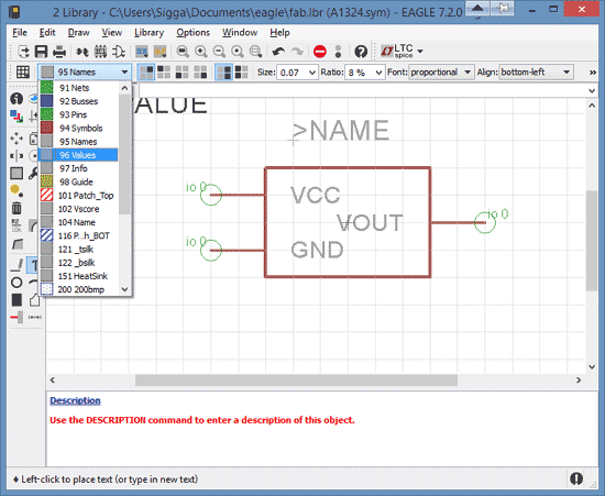
- There VCC is defined as pin1, VOUT is pin 2 and GRD pin 3.Now it was time to give the pins the correct name. That is done on the NAMES layer.
- Next was to give it value, again that is done on the appropriate VALUE layer.
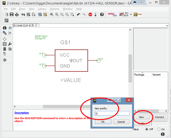
- Next we create the DEVICE - I gave my device the name A1324-HALL-SENSOR. Press PREFIX and give it the letter IC.
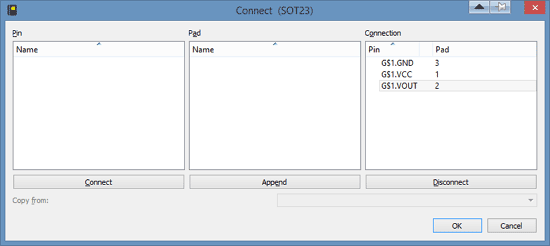
- Still inside DEVICE we connect the pins.
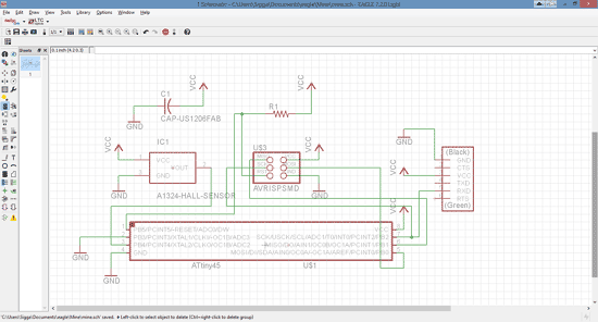
- Then we are finally ready to start work on the schematics drawing.
- It took me many design attempts to get my routing to work. I had to start over with a clean slate at least four times. One of the issues I had was when checking the layout with DCR (the design rules) the program kept giving me warnings that I could not go through the Hall sensor. I managed to find an alternative route, and that took some time. Later I found out that a simple solution to this is to take the board image to photoshop and edit there!
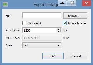
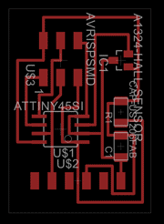
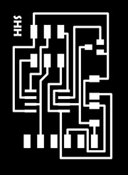
- When exporting use 1200 dpi and monochrome setting. Remember when exporting- always start with the interior. Draw the box for the interior, place it on the last layer, have that layer turned OFF and only the Dimension layer turned on when exporting. Then you can export the traces.
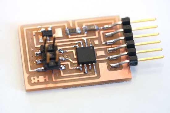
Stuffing the board
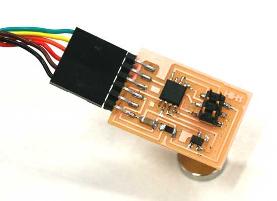
- Here are the result ready.
- Soldering went well and the continuity test was positive.
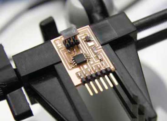
- The board ready for programming.

Programming
I have been having problems with the WinAVR compiler since day one, I am running on windows 8.1. This week though I found a solution to this problem at the avr freaks forum. From there I downloaded this file and copied into the WinAVR -utils/bin directory. That solved my problem!
This week I am using Neil's code without adaptations, It can be found at the homework page under Magnetic field.

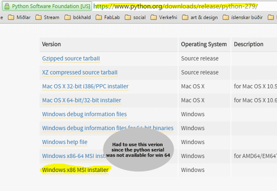
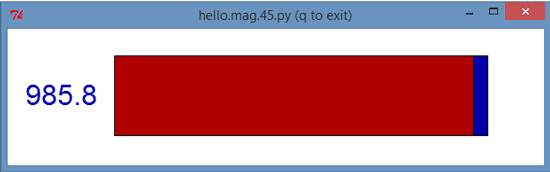
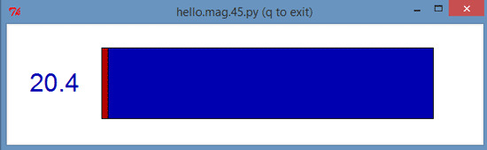
- The Hall sensor sends it´s reading back to the computer using a python interface. To be able to see the reading I set up Python 2.7.9.
- I started by setting up the Windows x86-64 version but had to uninstall that later as I found out that I needed something called SERIAL. That only works for the 32 bit version.
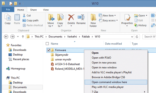
- Next step was programming. Shift- right click on the folder containing the programing files.
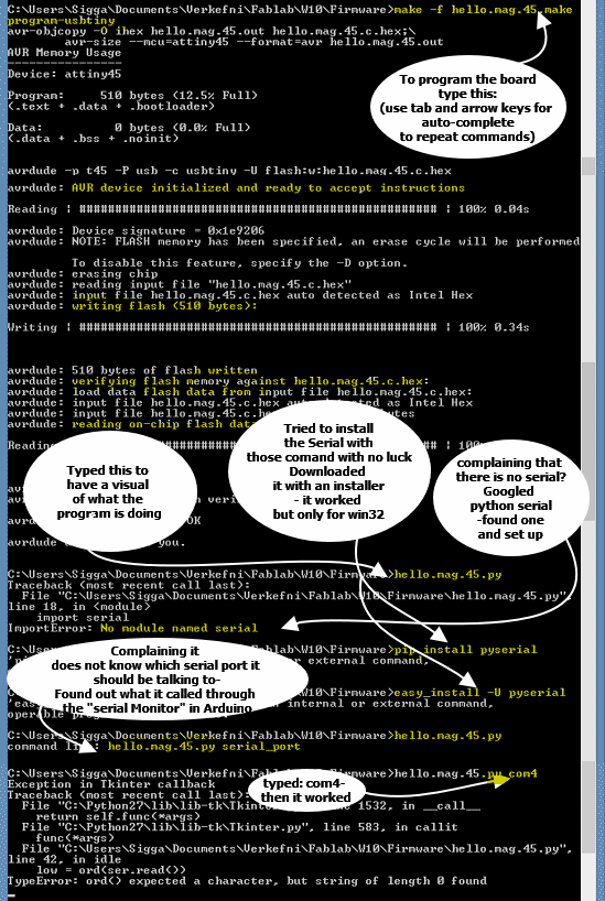
- Managed to work my way though the programming jungle.
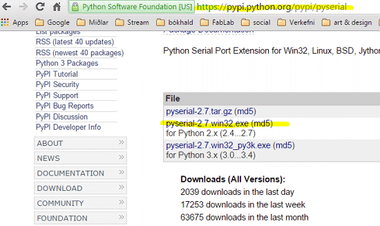
- After the error message: No module named serial. I googled Python serial and found this one, set it up and then it worked.
- The board in action.