


W11 ¦ Output Devices
Assignment for week 11
- Add an output device to a microcontroller board you've designed and program it to do something
- Link to this week’s homeworkpage
Stepper motor and hall sensor
This week I wanted to use the opportunity to program a Stepper motor for my final project. I added a Hall sensor the board as well. I intend to use the Hall sensor for positioning.
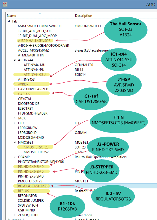
- These are the parts I used for the board.
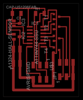
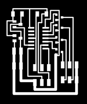
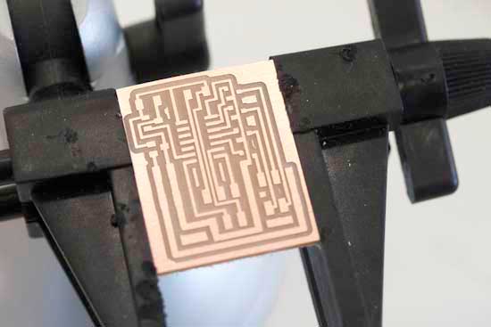
- The traces.
- Drawing in Eagle went well. I simply used my newfound knowledge of altering the image in Photoshop after having exported it.
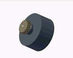
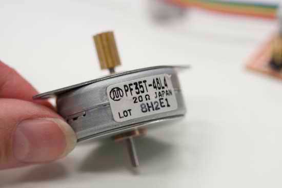
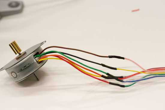
- In the lab I found a unipolar stepper motor. Here is the data-sheet
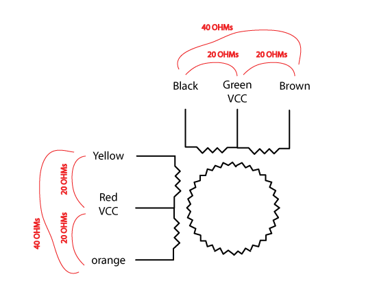
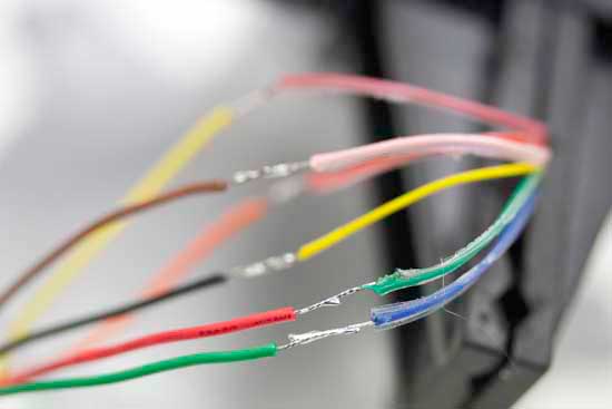
- The motor has six wires. To find out how to connect them I measured the current running through each combination.
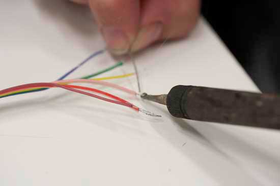
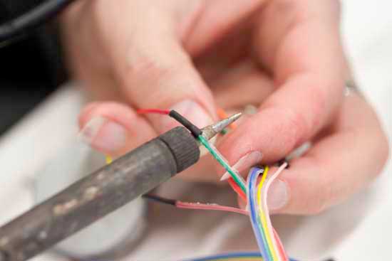
- Best is to pre-solder each wire and then solder the two ends together.
- It was bit confusing to find out where which wire should go. I started by attaching the six pin shoe to the cable, I then used the digital multimeter to find out which wire was what.
- Using heat-shrink to insulate the wires.
- The motor connected to power.
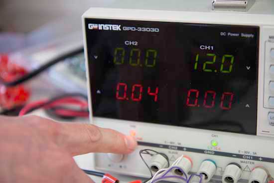
- I learned how to use the power supply to test whether the 4 pin power connector shoe was correctly attached to the battery wires. By taking down the current to 0.04 Amps but keeping the Volts at 7 I would not damage anything if it was the wrong way around.

Programming
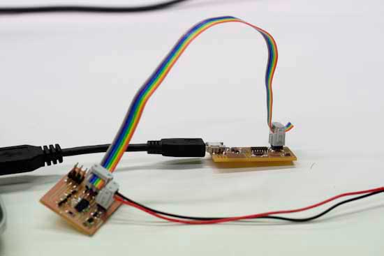
- Programming the board using Neil’s makefile went well. I intended to serial connect this board using the ISP connection. But I found out that the motor connection and the programming header are too close so I can not physically fit two six pin connector shoes next to each other.
- I got the motor to run bacwards and forwards alright.

Here is where my problems started. I now wanted to combine the Hall sensor program with the Stepper Motor program. That did not go smoothly. I have no prior experience in programming and even though I have been watching programming courses online I was no closer to understanding what needed doing to get these two programmes into one! For me this is like trying to compose a symphony only knowing ONE note.
I started by writing sudo code explaining to myself what needed doing. I then made an honest attempt to combine Neil´s two programs and adding my own requirements for my final project. After a long day of frustration I took a step back, had a good think about this and decided that I needed to program this in the Arduino environment. There I would at least stand a chance.
Here is my sudo code:
Programming in the Arduino environment
Working within the Arduino environment was more to my liking. Here is the code I managed to put together in the end:
/*
==============================================================================================
Stepper Motor & Hall Sensor -
Sigga Helga
FabAcademy  Mai, 2015

I am using ATtiny 44 AVR microcontroller with 8MHz internal clock and programming it with FABISP.
The TX (transmited from computer)= MOSI (MasterOutSlaveIn) is on PA6 and translates as Pin 5 in arduino
The RX (Received from computer)= MISO (MasterInSlaveOut) is on PA5 and translates as Pin 6 in arduino

I am using Stepper motor: PF35T-48L4
The data sheet:http://www.jameco.com/jameco/products/prodds/171601.pdf
It is a unipolar motor with six wires, the step angle is 7.5 degrees

Stepper is attached as follows:
Coil 1 = PAO=Brown is PIN 0, PA1=Black is PIN 1,
Coil 2 = PA2=Yellow is PIN 2, PA3=orange is PIN 3,
Red and Green are connected to power

This program controls one motor.  I have many motors connected and I am talking to many microcontroller all listening in on the same line
I am sending 2 bites of info, first is the ID of the motor, second is the new location.
When the microcontoller reconizes it's ID it acts on the order, otherwise it ignors it.

==============================================================================================
*/
#include
#define ID 1
#define stepsPerPosition 12  //if the motor has 7,5 degree steps that means 360/7,5 = 48 and each "step_cw" function consists of 4 steps hence 48/4 =12 for full circle
#define totalPositions 40
#define myHomePosition 1

int motorPin1 = 0;  //Brown
int motorPin2 = 1;  //Black
int motorPin3 = 2;  //Yellow
int motorPin4 = 3;  //Orange
#define delayTime 5

int hallSensorPin = A7;  //Hall Sensor reads magnetic field.  Using this to find the "home" positstion

int myCurrentPosition = myHomePosition; // position 0 does not excist....0;
int myTargetPosition = 0;// position 0 does not excist....0


SoftwareSerialWithHalfDuplex mySerial(6, 5, false, false); // RX, TX  for reciving and transmitting data

//=====================SETUP======================================================================

void setup() {
  pinMode(motorPin1, OUTPUT);
  pinMode(motorPin2, OUTPUT);
  pinMode(motorPin3, OUTPUT);
  pinMode(motorPin4, OUTPUT);
  pinMode(hallSensorPin, INPUT);

  mySerial.begin(9600);
  mySerial.println("hello you"); // debug line - prints "hello You" each time you reset the program


}


//====================MAIN LOOP====================================================================

void loop(){
  if (myTargetPosition ==0) {
      findHomePosition();
      myTargetPosition=1;
  }
    if(mySerial.available() >= 2 ){  // if 2 bytes or more arrived through the seraial communication line
            int targetID = mySerial.read();
            int newTargetPosition = mySerial.read();
            if (targetID == ID ){
              myTargetPosition = newTargetPosition;  // make my
              }
     }


      if (myCurrentPosition != myTargetPosition){
         moveOnePositionCW();
      }
 }

//==================DEFINING FUNCTIONS=============================================================


void whichDirectionToGo (){
 if (myTargetPosition > myCurrentPosition) {
    moveOnePositionCW;
  }

  else if (myTargetPosition < myCurrentPosition) {
    moveOnePositionCCW;}
}


void moveOnePositionCW (){ //clockwise direction
    myCurrentPosition++;
    if (myCurrentPosition == totalPositions+1) // if I am one over myTotalPositions I am back to square one (the counting for totalPositions starts at zero hence the plus 1.
        {myCurrentPosition = 1;
        }
    for (int i = 0; i < stepsPerPosition; i++) {  //each "step_cw" consist of 4 steps, so if the motor has 7,5 degree steps that means 360/7,5 = 48 and 48/4 =12
          step_cw();
        }
}

void moveOnePositionCCW(){  //counterClockWise direction
    myCurrentPosition--;
    if (myCurrentPosition == 0 )  // if I am one over myTotalPositios (-1)I reset the counter to start counting again
        {myCurrentPosition = totalPositions;
            }
    for (int i = 0; i < stepsPerPosition; i++) {
          step_ccw();
        }
}


void findHomePosition() {
     int hallSensorValue = analogRead(hallSensorPin);
     while ((hallSensorValue > 450) && (hallSensorValue < 550)) {
       moveOnePositionCW();
       delay (1);
       hallSensorValue = analogRead(hallSensorPin);
   // while (1){                                    //Debugger- sends the Hall Sensor's reading to the console window
         mySerial.write(hallSensorValue);


     }
    myCurrentPosition = myHomePosition;

}
//Forward steps- Clock wise = cw
void step_cw() {
  digitalWrite(motorPin1, LOW);
  digitalWrite(motorPin2, LOW);
  digitalWrite(motorPin3, HIGH);
  digitalWrite(motorPin4, LOW);
  delay(delayTime);
  digitalWrite(motorPin1, LOW);
  digitalWrite(motorPin2, HIGH);
  digitalWrite(motorPin3, LOW);
  digitalWrite(motorPin4, LOW);
  delay(delayTime);
  digitalWrite(motorPin1, LOW);
  digitalWrite(motorPin2, LOW);
  digitalWrite(motorPin3, LOW);
  digitalWrite(motorPin4, HIGH);
  delay(delayTime);
  digitalWrite(motorPin1, HIGH);
  digitalWrite(motorPin2, LOW);
  digitalWrite(motorPin3, LOW);
  digitalWrite(motorPin4, LOW);
  delay(delayTime);
}


//Backward steps - Counter clock wise = ccw
void step_ccw() {
  digitalWrite(motorPin1, HIGH);
  digitalWrite(motorPin2, LOW);
  digitalWrite(motorPin3, LOW);
  digitalWrite(motorPin4, LOW);
  delay(delayTime);
  digitalWrite(motorPin1, LOW);
  digitalWrite(motorPin2, LOW);
  digitalWrite(motorPin3, LOW);
  digitalWrite(motorPin4, HIGH);
  delay(delayTime);
  digitalWrite(motorPin1, LOW);
  digitalWrite(motorPin2, HIGH);
  digitalWrite(motorPin3, LOW);
  digitalWrite(motorPin4, LOW);
  delay(delayTime);
  digitalWrite(motorPin1, LOW);
  digitalWrite(motorPin2, LOW);
  digitalWrite(motorPin3, HIGH);
  digitalWrite(motorPin4, LOW);
  delay(delayTime);
}
Here is a vido showing the motor in action moving to the right postion. The video was actually shot in week 14 when I had also mangaged to establed networking communication between the microcontroller and a website sitting on a server, using a node.js bridge: