19. Project and development
I describe here the design flow of my Final Project. In the end, there are varions tests how the electrolysis works and some description of the paths I didn’t take. Unfortunately, I didn’t fail fast.
Right in the beginning I would like to praise the weekly tasks for helping me to advance the final project. The ones that especially have helped me were:
-
The principles and practices week where I searched information for my final project and decided to try electrolysis.
-
The project management week where I prepared the git pages which were neccessary for documenting the final project..
-
The computer aided design week where I presented the first version of the electrolysis pool.
-
The electronics production week where I manufactured the UPDI programmer.
-
The 3D scanning and printing week where I learned 3D printing quite neccessary in the final project.
-
The electronics design week where I designed the microcontroller I use in the project.
-
The computer controlled cutting week where I learned to use the laser cutter neccessary for producing the windows in the pool and the float.
-
The embedded programming week where I learned to use Arduino studio and the programming techniques used in the final project.
-
The output devices week where I learned to program LCD display and use the registers and memory of the LCD controller board. Unfortunately, keep it simple, there was no memory to implement the temperature and humidity bars for the LCD display. I used directly parts of the program code produced on this week.
On this week we also learned to measure the current requirements in the group work, which was usable skill when measuring the current consumption of the final project. I replicate the same measurements here.
-
The input devices week where I learned to program LCD display and use the registers and memory of the LCD controller board. Unfortunately, keep it simple, there was no memory to implement the temperature and humidity bars for the LCD display.
-
The networking and communications week where I learned to use a bus for transferring signals and to use UPDI to UART USB cable included in the final project as component. The bus I use in the final project is derived from the bus I designed there.
-
The Interface and application programming week where I refined my skills in reading and writing on devices and how to use and connect multiple devices on my microcontroller board. The code I use here is mostly written on this week.
-
The Invention, IPR and Income week where I prepared for putting video on my page and making a poster. I also learned about Fab licence I am using in the final project. However, my project is used on the users own responsibility.
Introduction
I decided to do a electrolysis pool for the final project. Designing of the working small scale electrolysis system is quite trivial. I was tempted to use my experimental system as electrolysis pool and concentrate only in doing a control unit as the final project, but I was told that it was not possible.
Before building my setup, I used a lot of time testing the materials and learing how to do a small scale electrolysis, which electrodes do work and which ion combound is the best for the purpose. I will leave most of the details of my experimental systems out of the documentation, but it was fun.

Here is a video of my experimental setup using FabLab Oulu lab power supply and Glauber’s salt as an ion source.
There are Electronics of my own design integrated into the final project. I decided to use the board I designed during the Electronics Design week.

The board is connected to a computer with the PL2303HX USB to TTL RS232 COM UART converter cable. The cable was used in the Interface and Application week.
The board is connected to the relay module (sr1y) and to the measurement module (DHT22). These devices were also introduced in the Interface and Application week.
The LCD display with the LCD controller board used in the Output Devices and also in the Input Devices week is also used in the setup much similar way and the instructions how to use the LCD display and the controller board is described there. The number of the pins available required, that the line originally dedicated for the key press is used as relay output line.
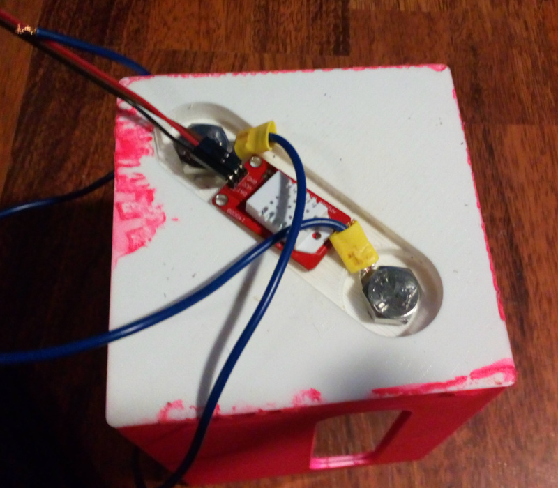
There is a panic button designed by me inside the case, for emergency stop of the relay. It is currently not connected to the case, but adding it to the case is trivial and would provide a manual elecrolysis on/off functionality.
The external modules could have been replaced by the design of my own, but use of relay modules, sensor modules and LCD controller modules is common in Arduino based embedded development and the sensor modules are widely available. I also decided to separate control logic casing and the water pool, so the sensor and the relay are located other case. I still need some feedback, if the originality cirteria for the I/O part is currently met. If it is not currently met, then I would like to add the cpu with a bit larger memory and use Serial library to implement the UI I already designed on the Interface week. It is directly compatible with this project, when the code bits from that code are moved to this project. My conclusion is that my Final Project is using electronics designed by me
There was also a requirement fo 2D and 3D designs integrated into the final project. The electrolysis bowl (Pool), Float for collecting the gas, stand for the Pool and control unit case are all 3D printed. The Float and the Pool use windows used for viewing the accumulating gases. The windows are laser-cut to fit into the design. Therefore both 2D and 3D designs are integrated in the project.
What parts there are in the project?
The designs for the 3D parts include:
-
Design for the control unit, Version Dec the 1st 2022. (This one was used in the experiment, but it required some work with the holes and removal of failed installation structures for the parts.
-
Design for the control unit, Version Dec the 4th 2022 with modifications. Positions of holes are moved a bit, holes for the LCD should be in the right position and there are material removed inside in order to provide mariginally more space and maybe also shorter printing time and have a bit lower material consumption.
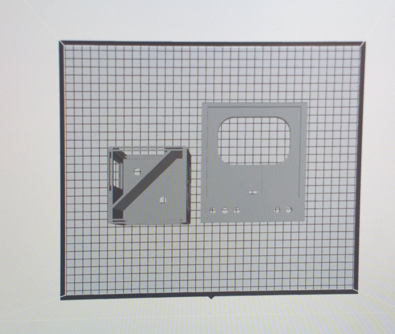
Both parts, upper and lower are in the same file as components (Component 3 and Component 4). The printing time is reasonable to print both parts at the same time.
-
Design for the pool and the float. Both are in the same file. You might want to export the parts as different .stl:s for printing because of long printing times.
-
Prototype design for the pool stand, Version Dec the 1st 2022. This has major problems and is only included here, because the early experiments are concluded with it.
- Revised version for the pool stand, Dec the 04th 2022. This one should be ready to use with less corrections. It has readiness for keeping the sensor in the stand and it should be possible to assemble this one without grinder.
The designs for the 2D parts include.
Microcontroller board KiCad_pro file.
Microcontroller board KiCad_pcb file.
Microcontroller code. The code is built based on several publicly available examples.
Note, that the Pool has designed for windows space of 2.13 mm width. The float has windows space of 1.28 mm after scaling down to 90%. That means, that the closer match for the float windows is 1 mm acrylic with silicone sealant fixing the leaks. Even 2 mm acrylic is tight to get installed.
Links to the files will obviously be inserted here, when the documentation advaces to that point.
Note that the files are distributed under “fab license”:
**(c) Antero Metso 30.11.2022
This work may be reproduced, modified, distributed, performed, and displayed for any purpose, but must acknowledge “project name”. Copyright is retained and must be preserved. The work is provided as is; no warranty is provided, and users accept all liability.**
What needs to be done:
-
Control unit case holes should be resized.
-
Stand design file needs adjustments.
-
The control unit closes, but is tight. Deepness of the lid could be adjusted and some isolation could be added between connectors.
-
The design already uses connectors. Wire ends use pressed loops now. Decent soldered loops should be added or Abiko loops should be soldered to the terminating pins of the wires, or female pins should be soldered to the loops.
-
The Float needs to be scaled down a bit in order it to float more freely.
-
The ABS material used now in the float is more difficult to paint. Consider reprinting using other alternatives.
-
While resizing the Float can be done easily, this affects on the fit (thickness) of the windows in the Float design. Manual adjustment was required. Therefore, changes are required in Float design, Valves design and to the windows file.
-
The wiring could be ordered better inside the case.
-
Connectors under the Pool unit should be changed.
When changes are done:
The next time available to do the changes is Saturday, the 3rd of December. The redesign of the windows and lids will be done then. If everything goes well, new parts are printed during the weekend. The designs in the electronics depend on the feedback, which may come or not come.
There are exams coming on the following week. I need to postpone doing rest of the fixes after that. (2.12.2022 situation.)
Other design considerations
- The electronics is powered by USB via USB to UART cable. UI functionality was not implemented because of memory issues. It was tested separately and it worked. All the required libraries did not fit to the memory (over 1000 bytes missing). If the UI functionality is considered important, the microcontroller should be replaced with more powerful ATtiny. If really required, this is an easy task and required only redesign of the circuit board following the quidelines in the Electronics Design Week. Doing it would add workload to the project and could also be considered as a Future Expansion option.
-
The button and the led are not used now and could also be removed. Pressing the button affects on the relay now, bit this requires opening the case.
-
The rubber paint I used is fluorescent. Some UV leds would be a nice finish.
What has worked, what hasn’t?
Here is what I learned from testing the setup.
What is working?
-
The unit turns the relay off and stops the process if temperature exceeds the limit (35 degrees C set now in code).
-
The display is working correctly and shows what it is supposed to show indicating that connection between microcontroller card and the control board as well as the connection between the control board and the LCD board works.
-
The connectors outside the box are working.
-
The wires inside the box use connectors instead of prototyping pins. Not a sinle single pin wire is left.
-
The electrodes get power when the design is turned on and temperature (measured by a temperature sensor under the bowl measures temperatures under 35 degrees C.
-
The control unit logic works on USB power. Charger or computer can be used.
-
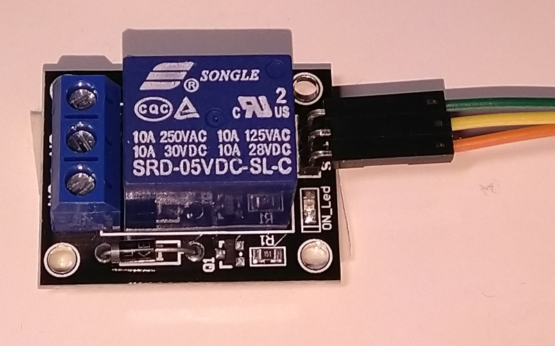
The power distribution from high-current / voltage source to the pool works. The relay is rated for 10 A.
-
The device produces now hydrogen and oxygen, which are collectable by collecting the bubbles rising from the electrodes.
-
The Glauber’s salt solution is not immediately destroying the acid resistant steel electrodes, so the materials selected are working.
-
The fit between the control unit top and control unit bottom was satisfyingly perfect. The parts stay together even if not connected with screws.
What is not working?
-
I painted the float at home in small space, resulting too thick layer of paint and very long drying time for the rubber coating. Rubber coating with clear layer is required to make the 3D printed material water and airproof. Therefore the Float used for collecting the gases is not tested. The float is still drying and needs the clear layer after it is dried and the protective layer on the windows is replaced.
-
The Float design was scaled down, therefore the window thickness was also scaled down. The windows require some fine tuning in order to fit.
-
Also test show, that the lower part of the case could actually be removed so that there is no supporting layer under the acrylic windows. The supports were so thin that they could not take fine tuning, so I removed the thinnes part manually from the maufactured piece.
-
The sizing of for the sensor in the stand did not fit. The stand needs redesign. The sensor position was not correctly sized and the holes made for the wires were not placed correctly. Plastic ring had to be removed from the connectors. This resulted the connectors extending under the stand. This was compensated by adding pads under the stand.
-
The stand holes and the holes in the control unit case had to be manually enlargened. Larger holes are needed in both of the designs.
-
None of the supporting structures in the bottom control case part were correctly sized. I removed the details manually. While the wiring fits now, thanks to using flexible bus, some redesign could be used.
-The same part could use some redesign in order to make the screw tops go under the surface of the case.
-
The float needs some kind of valves so that air can be let out and the gases kept in. The simplest way would be just closing the holes and removing the air manually. The issue is the 3D printed parts letting the gases out, so laser cut design for a valve or commercial small aquarium valve could be a solution.
-
The computer control user interface had to be dropped. The system now inputs only humidity and temperature and shuts down by pulling the wires from plugs or if temperature exceeds the set temperature.
-
There is still a small leak somewhere in the pool. While the pool can be demoed with the very small leak, it is a nuisance and needs to be found.
-
I redesigned the wiring harness. Before that, fitting the card to the seat I had designed to it resulted in a connector stripping out of the board. Fortunately I had used the same design as before, so I still had spares left from the networking week.
What questions needs to be resolved?
-
Is the computer UI necessary? If it is, a new circuit board is needed.
-
How to implement valves, if more fine tuned way to collect the gases is required.
-
Is it required to limit the incoming current over 10A? Is the 10A for maximum current consumption or maximum input current? If current consumption, this could be adjusted by ion content.
-
What kind of internal structure is required for the project? All the single pin connections are replaced with larger connectors. The extra pin holes in the connectors are not filled and the connectors are not keyed. Is this required?
-
Have I missed the January deadline.
What will happen next?
-
The list of the changes seems a bit excessive, but it is actually not so bad. I have everything fresh in my memory and the complexity is not too much to handle the project as a single object in my head. It is 2 - 3 days of days work, delayed mostly by availability of 3D printers.
-
I need confirmation that this design meets the requirements for the final project and feedback which of my changes are required and which are not.
-
I need to know, if I can still graduate on January.
-
Otherwise, I will redesign the parts needing immediate adjustment and 3d print the parts in FabLab Oulu.
-
I will update the design files accordingly.
-
I need information if a computer UI is a required feature. There is still a button and a led line unused in the current board, but adding Serial library I used in the interface week to the code would result in too big code to fit in the memory of ATtiny used, unless some “magic” is used. A pin compatible cpu with more memory would be nice.
What have I learned
General thoughts
-
Designing things are fun, however there are other goals in life too which needs some attention. Unfortunately, the fun can’t always come first.
-
It is really easy for me to use excessive time in some interesting details in the design, when moving on would be more beneficial for meeting the deadlines. However, things like making the I2C bus finally work the first time after using a lot of time in details are really good experiences which give energy for doing other things. So, I don’t know if the time is so badly wasted after all.
-
When you are in a hurry, it is guaranteed that FabLab is closed for Saturday or for the previous evening before the deadline.
-
I have other, mostly compulsory things to attend on daytime before 16.00, so the limited access to the Fablab (it closes at 19.00, open on Saturdays 9-15 and closed on Sundays) really slowed down the project. Especially that “closed on Sundays” part seems like an awful waste of lab time for me. I had hardly time to design a detail at the evenings before I had to leave it 3D printing for the night. This resulted on some bad design decisions I need to redo now.
Skills
-
I can do now 3D design for the objects. However, I still lack a lot of basic knowledge in quite general things like scaling down the object size of the design. My learning curve in 3D is quite deep now. For example, I have now designed a lot of parts as separate designs, which I probably should have added in the same design.
-
I learn all the time new things about 2D desing which I would like to try. I really wanted to use bending acrylic on the laser cutter in this project, but that would have required more time in FabLab than I had. Transparent electrolysis pool with some thought put on the design of the form affecting on how the bubbles would move up, like in lines, would have been just cool to do.
-
Connectors and wiring part is interesting too and I think I have learned something on the system level planning while re-designing it. I had to do two redesings 30.11.2022 in order to make the design both work and be reliable enough.
-
I have now learnt to make cabling and make a bus from the ribbon cable in order to add or remove functionality of the device. The sensor and relay are added to the common bus with connector.The LCD display is not in the same bus, but it originally was. I needed to wire it separately to save space in the case.
-
I have also got some ideas how to make more out of bus design in the future. I am planning to learn how to use 3D printing to sink parts inside the casing. A bus placed inside the walls of the case wouldbe nice to implement, the functionality could just be pluggend in the 3D printed case wall at the correct places, like power plugs are used in the walls.
-
I have learnt about the memory requirements of the libraries. I still need to understand the logic in the compiler, if only those components which are needed are included, or if everything is included. This is, if it is possible to remove unused library components in order to save space?
-
I have definitely learned a lot about the electrolysis and the materials. I used a lot of time in trying to find semi-permeable membranes, which would have allowed downscaling the size of the electrolysis pool. Especially an idea to use two-sided circuit board as electrodes, which probably could be done with careful selection of materials, perhaps plating and ions used in the pool was something I would have liked to try with the semi-permeable membranes. That would have allowed to do some really interesting things.
A full bill of materials to replicate the final project.
This needs to be revised, because some parts I considered using were not used and others were used instead. Also, I am not sure how to count the price of acrylic and 3D printing materials. If I need some spray paint or tape for prototyping, do these count to the bill of materials?
Estimated 500 gr of FabLab materials, 25 euros / kg = 12.5 euros These contain 3D prints and 1 mm plexi glass for the float (depending how it is scaled), 2mm plexi glass for the pool. - 197 gr of PLA for Raise3d, 289.6 cm3 material (M30_BLK) and 63.4 cm3 support material (SR35) for Stratasys. - ~300 cm2 transparent acrylic is required.
Electronics
Microcontroller
A piece of circuit board. About 3.3 x 2.3 cm. Price included in FabLab materials. - 1 uF SMD capacitor. Estimated 5 cents. - 499 ohm smd capacitor. Estimated 5 cents - ATtiny 412 microcontroller 0.70 euros - A smd led. Estimated 5 cents. - A keybutton. Estimated 30 cents. - 2 6-pin 1-row connectors for each end of the circuit board. 0.20 euros.
Input/Output
- Keynes SR1y relay module. 16 euros.
- DHT22 sensor module. 10 euros.
- PL2303HX USB to UART cable converter 10 euros.
- LCD display module with controller. Estimated price 10 euros.
Connectors and wires
- Female banana connectors, 14 pieces. 0.60 euros / piece
- Male banana connectors, 14 pieces. 1.50 euros / pair.
- Reel of blue wire, 8 euros. Only 1.50 m required.
- Reel of blue wire, 8 euros. Only .50 m required.
- 14 banana sockets: @ 0.60 euro
- 2 Green
- 2 Yellow
- 2 Blue
- 4 red
- 4 black
- 14 banana plugs, @ 0.75 euro
- 7 black
- 7 red
The bus
- 6 cm 16 pin flat ribbon cable. 0.20 euros.
- 5 female 14-pin two row ribbon cable push-through connectors. @ 0.40 euros.
-
18-pin 1 row straight pin headers. 0.20 euros.
-
Wires between modules, included to Fab acdademy lot.
- 15 female to female jumper wires for constructing the cables. 1 euro
- Insulation sleeves, blue, yellow, green small size, red larger size, ~ 4 euros.
- 18 pin pin row. 0.20 euros
General screws 3.0 x 16 (INOX CSK CHIPBOARD 3 x 16) 4 eur. Any compatible screw goes.
Cases
- SCOTCH Invisible tape for painting job 10 eur.
- SCOTCH Two sided tape (for prototyping, fixing problems). 5.90 eur.
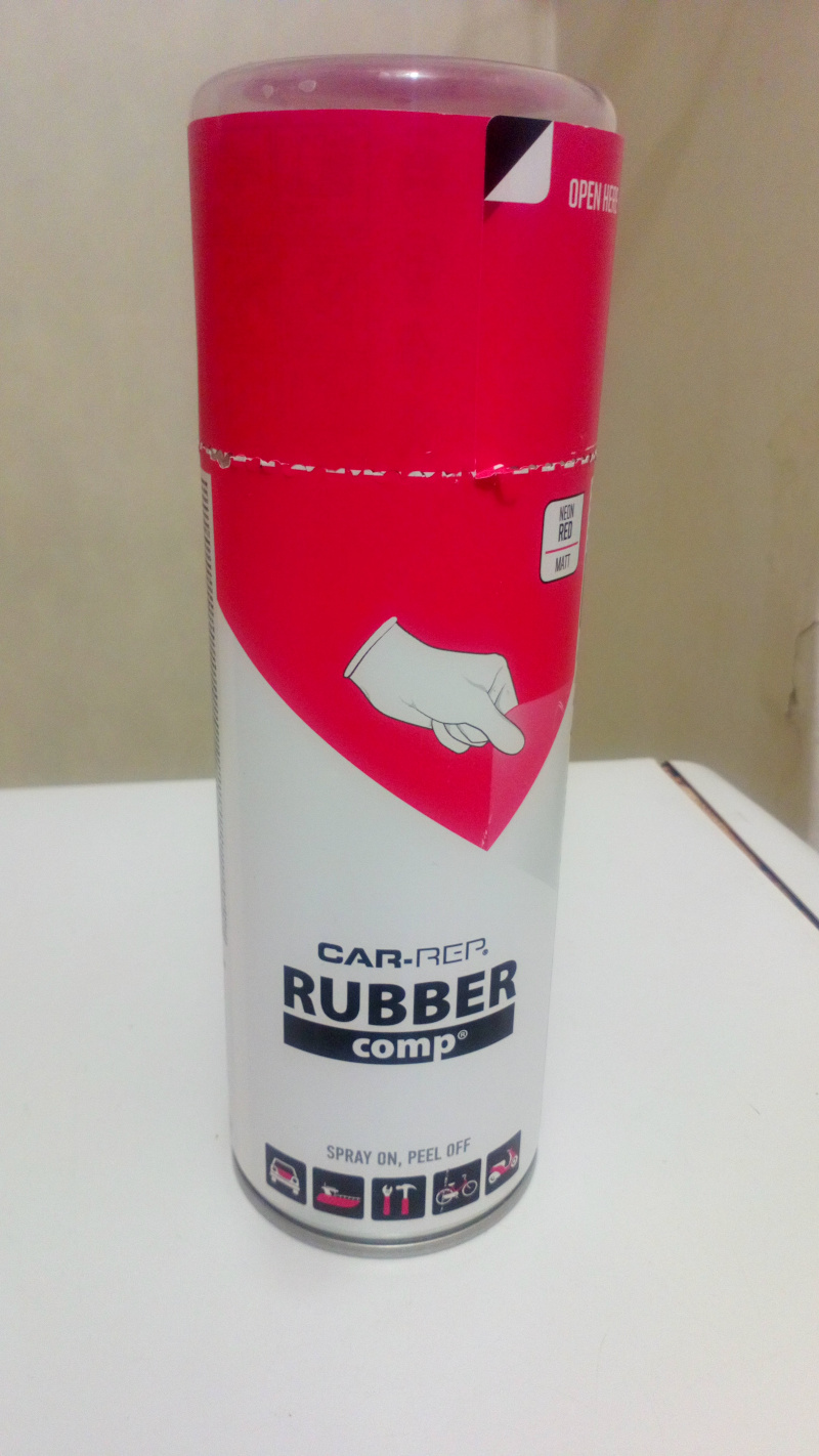
- CAR Rep plastic primer 7.99 eur
- Pink fluorescent rubber paint. 12 euros.
-
Clear coat spray. 7.99 euro.
-
Electrodes. Acid resistant steel bolts and nuts. 10 eur.
-
Sika Silicone sealant for making the pool waterproof. 6 euro.
- Some thick tape (I used Gorilla tape, SCOTCH Invisible tape above will do) for constructing the mold for waterproofing the bottom of the pool.
- Set of pads, 3 euro.
Total: 220.80 euros, greatly exceeding all my estimates.
Optional: USB charger can be used to power the project instead of a computer with traditional USB slot.
Total estimate for the project at this point: 145 euros. Note that a lot of that money could be divided to tens of project, for example paint and tape costs. Those costs could also be avoided by using cheaper alternatives.
Description of the final project
I started doing the components in July. Here I describe some of the components and the way how they were designed and printed.
Float
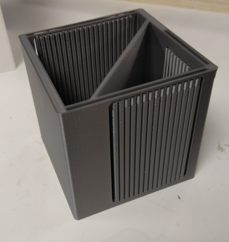
The purpose of the float is to collect gases produced by the electrolysis process. The general idea is that the float is originally filled with electrolysis solution and then slowly starts rising up when the gases accumulate. The float is divided in two chambers. The volume ratio between the chambers is calcuated to be 2:1, reflecting the hydrogen-oxygen ratio produced in electrolysis. When the float is opened, the hydrostatic pressure will push the gas out while the solution fills the float. The effect can be helped by pushing the float down manually.
The first version of the float was printed on grey PLA.
Layer height of 0.25 mm, shell width of 0.8 mm, infill of 10% and infill speed of 80 mm/s were used. I used the settings recommended by instructor or someone helping me then on the FabLab. The estimated print time was 13 hours and it used 123.6 g filament.
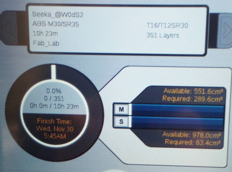
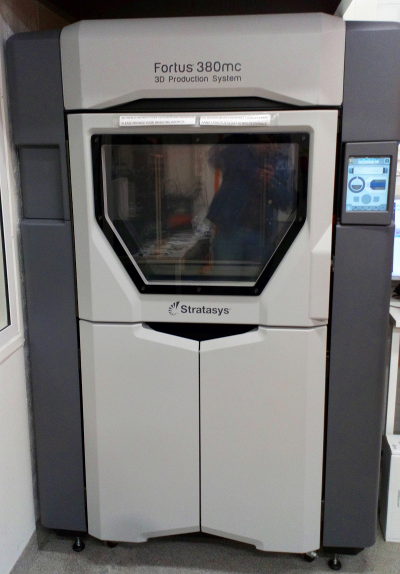
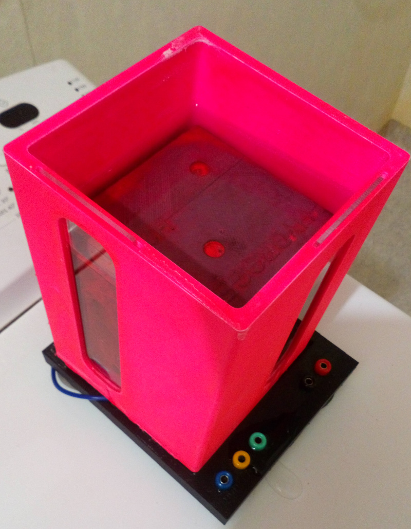
The second version of the float was printed on black ABS in Stratasys. It was printed together with the pool stand. In the image, the acrylic window is already installed into the design.

The printing time was 10h 23 min, 289.6 cm3 material (M30_BLK) and 63.4 cm3 support material (SR35) was required.
It now appears to me that infill of 10% for a component designed to be air and waterproof probably wasn’t the best recommendation I have got and was probably given materials savings in mind. However, it has the good side that it made the float lighter and it floats easier. There would have good reasons to use a lot more dense parameters when printing a float designed to contain hydrogen, which has a small molecule size. The result was too fragile and leaked both gases and water.Additionally, grey PLA used there was considerably harder to paint compared to the white one used in the pool itself.
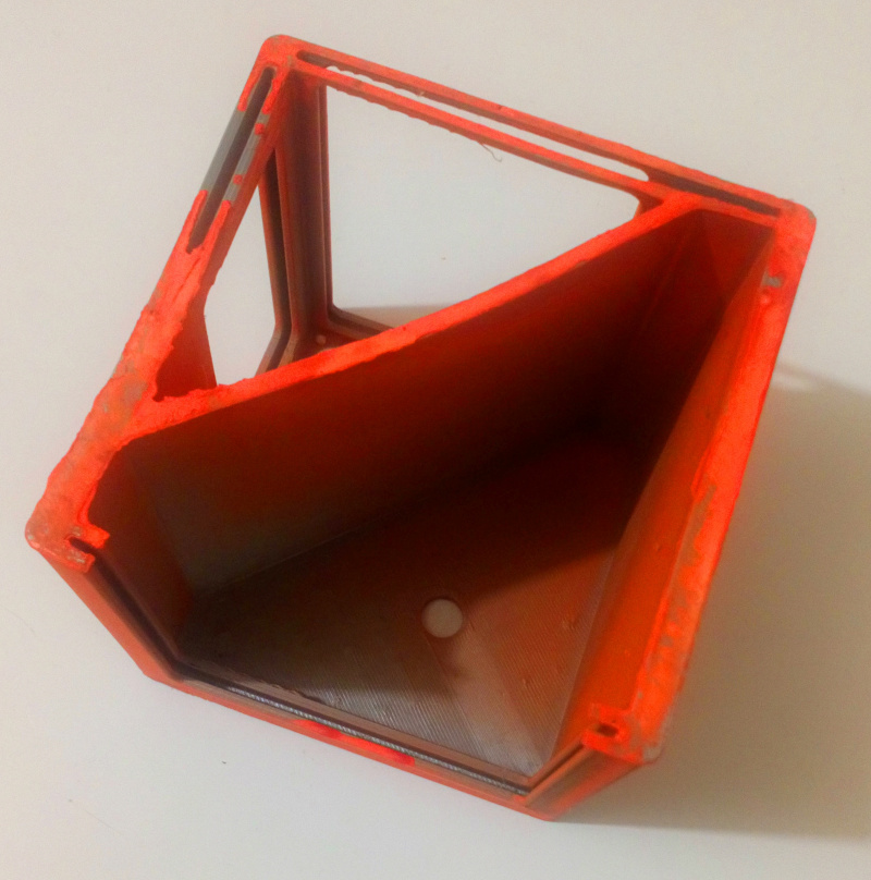
The status of the float today, after being painted orange (after applying plastic primer) and after being in the sun for a while, demonstrates the problem I faced: The part didn’t hold the form. Some gap was designed based on what I learned on the Computer controlled Cutting Week about tolerances and kerf between the pool and the float, but I did not factor in the structure itself warping. That part could not be used and I ended up trying other designs for the float.
The float has holes over it for letting air out and collecting the gases. There were connectors designed and printed for that part. Unfortunately, I could not ffind the printed parts. They could have been reused.

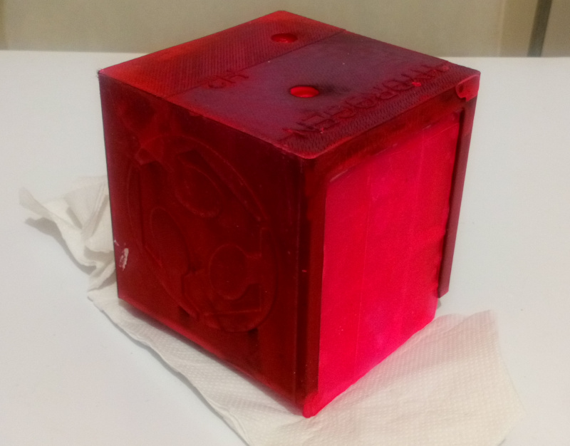
A new print was required. While the previous version was printed on June, the new version was printed on the end of November. Unfortunately, the lab was closing so I just had time to add some text, logos and downscale the model. I did not do the downscaling properly, but followed the lab assistant’s suggestion to use hotkey for scaling down the model without any consideration.
New version was printed on abs this time, with Fortus 380mc making it considerably more water and airtight.
The model was printed with unfortunately even more quickly designed stand.
The resulting model looked a lot more solid.
The items printed with Stratasys require extensive time in NaOH solution in order to remove the supports. Some supports were still left when the FabLab closed early, I had to remove those with force. See the white supports in the lower corners of the window openings.
However, the model still had to be painted in order to make it waterproof and able to contain the hydrogen. I used again plastic primer and added then rubber coating. However, last time I could do the painting outside at June. Now it was too cold and paint would have frozen in the air. I had to paint it in shower with very short distance between spray and the object. This resulted really bad resilts. Fortunately, the results are not final and another layer of plastic primer and clear coating should make the float usable. The rubber paints I use also react on blacklight, so the result should be stunning.
The float was scaled down to 90% in order to make sure that it fits. That was a bit too much: Smaller change would have increased the tolerance between the pool and the float, but still made the windows designed to fit. I re-used the previous windows but now I had to adjust the windows manually.
The float after the rubber paint was cured. It has a kind of interesting pattern in it. I decided to give it a try before any more surface finishing. Curing takes too long time at this phase.
The tapes were removed. The float looked just fine to me.
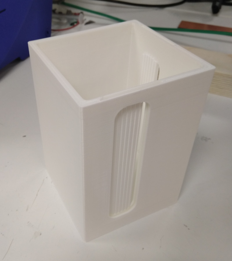
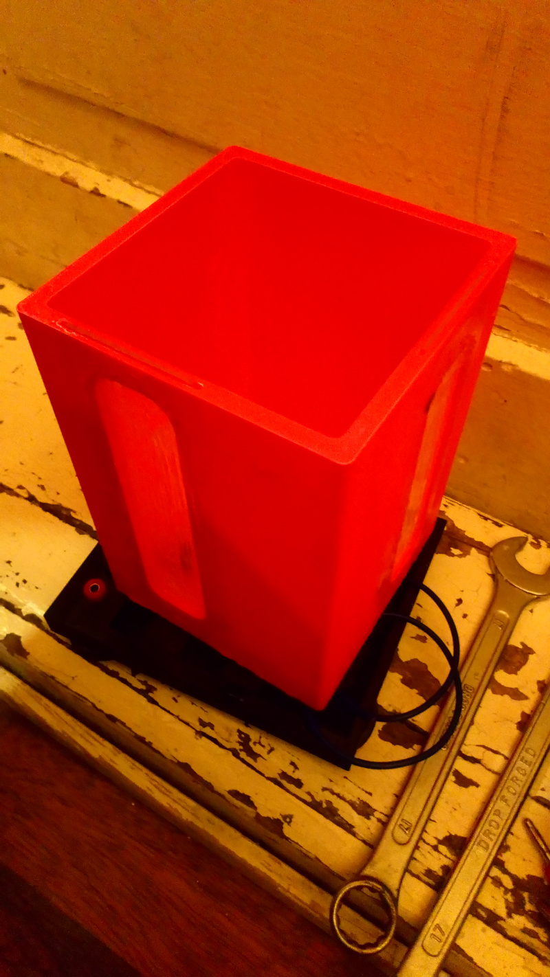
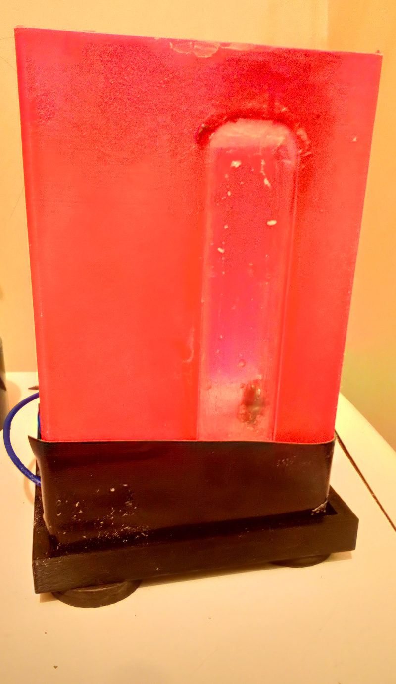
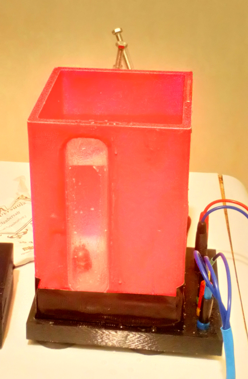
Pool
The function of the pool is to contain the water-conducting ion solution and hold the electrodes used in the electrolysis process. In order to work the pool should be waterproof but unlike the float, it needs to contain only water, not gases. Therefore using dense printing in it is not so crucial, provided that the surface is coated properly.
The pool was designed in Fusion 360 and moved to the slicer as .stl file, like all the other 3D printed designs printed in this project.
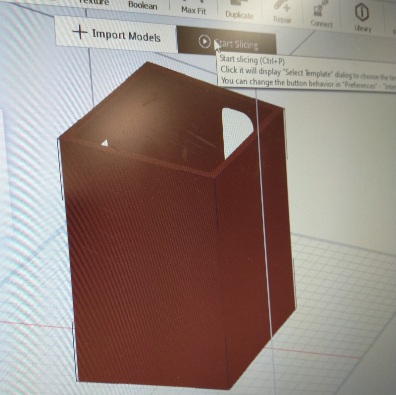
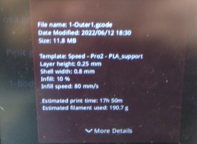
The pool was printed in white PLA with a Raise3D printer with layer height 0.25 mm, shell widht 0.8 mm, infill again only 10%, infill speed 80 mm/s. Estimated printing time was 17h 50m and the estimated filament use was 190.7 g.
The pool was coated with plastic primer and them rubber coating for providing the main insulation against the water. The rubber coating is quite fragile, so it is also protected with clear coating.
The painting was done outside. The part was let dry outside for days.
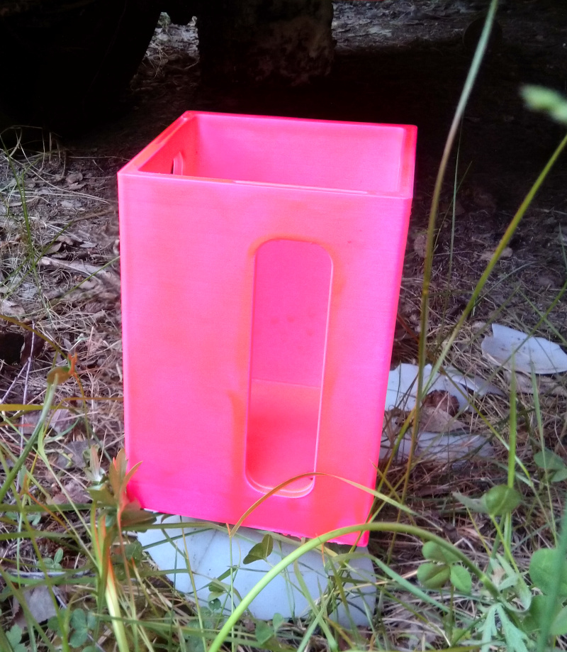
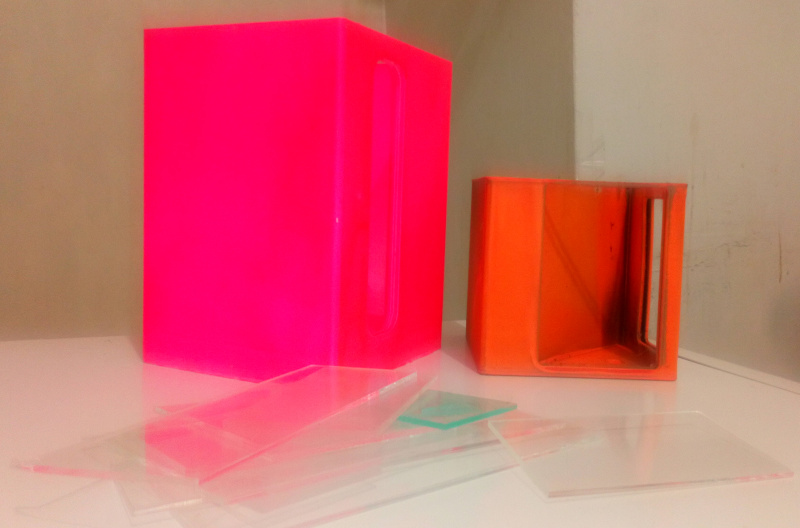
The windows were 3d-printed from acrylic at the same time as for the float. The windows were designed in Fusion 360 and prepared for cutting in Inkscape. Note the difference between fluorescent painted old float and rubber painted pool after spending a summer outside. Apparently rubber painting is a better option, or as I suspect, the white PLA was of better quality.
Because of the nature of the 3D-printed objects, it is very likely that the pool will eventually leak water. Therefore, no electronics should be placed directly under it without making sure that it is covered and the water has some other way to go. This resulted in a design decision to use separate case for electronics. The humidity sensor can be used to detect the leaks and the value rose rapidly when the leak occured.
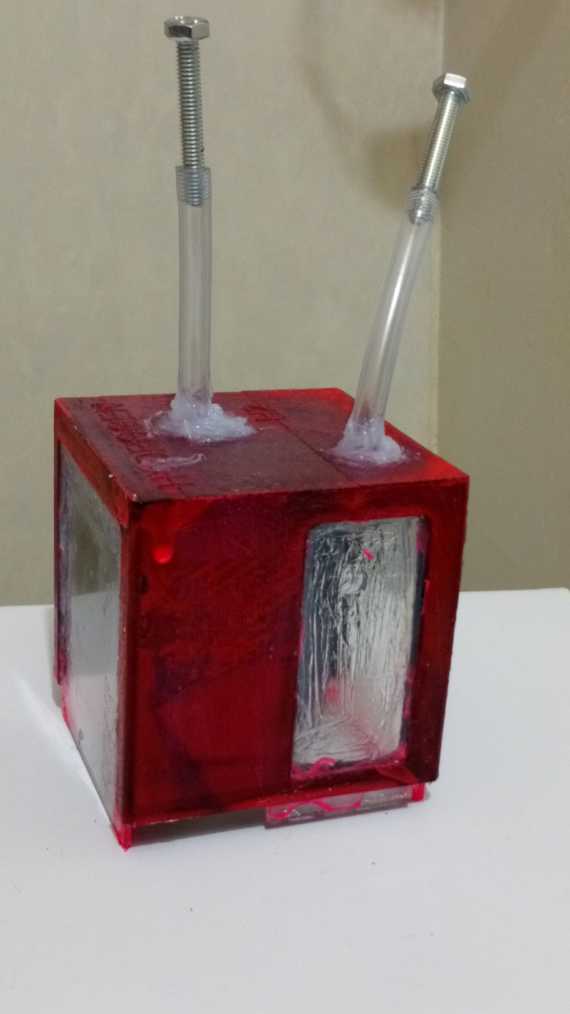
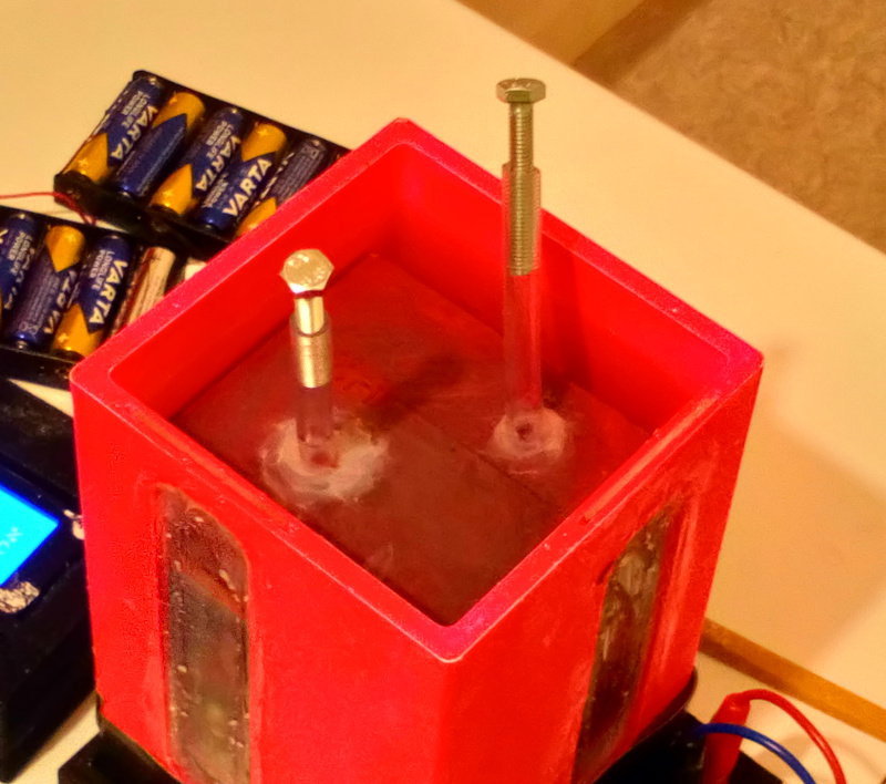
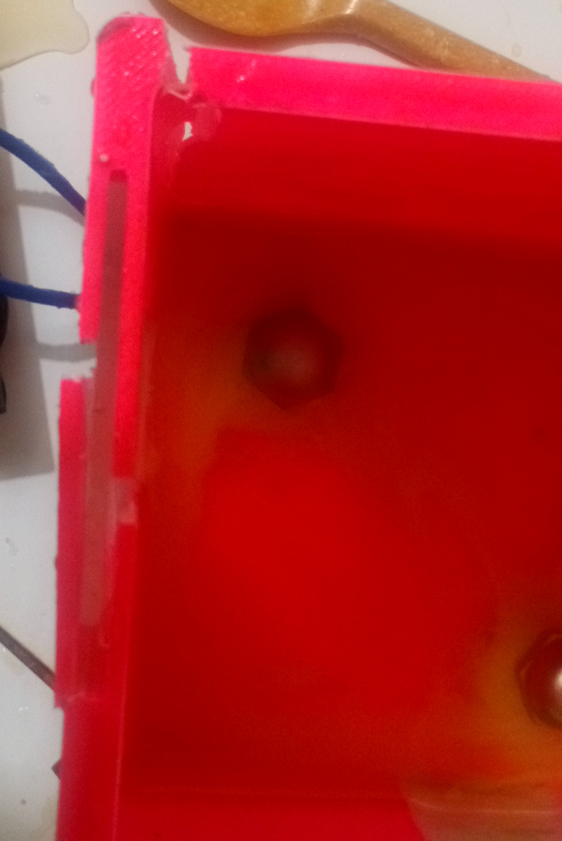
Acid-resistant steel bolts were used as electrodes. This setup makes it possible to change the top nut easily, if there were serious corrosion in the electrodes.

The bolts were installed in to the bottom of the pool.
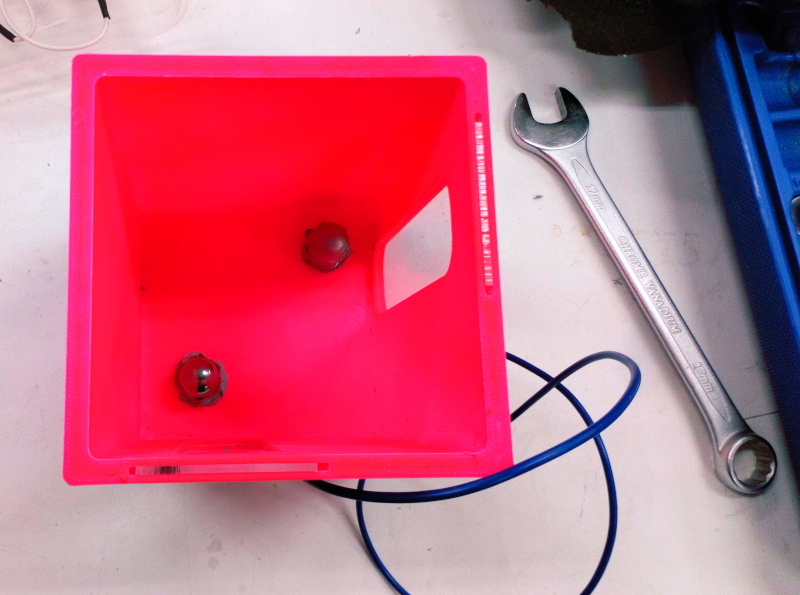
The image showing how the wires and the sensor are installed. This image is obiously of prototype phase, because the separate wires in the DHT22 connector and wires not soldered to the Abico connectors. The original idea was to use the bolts to install an additional part to the bottom of the pool containing the connections and perhaps electronics. The groove is unfortunately not deep enough for DHT22 sensor module, there is a hole in the stand now. The location of the sensor is discussed more later.
The pool contains windows for viewing the water level in hydrogen chamber and oxygen chamber in the float. In the bottom of the pool there is some room for fastening the electrodes and connecting the wires to the pool.
DHT22 module was used. The sensor itself requires only minimal logic. It is quite slow to read, so reading it too often is not recommended. I also prepared for a case that the module itself is not considered as self-designed I/O by purchasing two DHT10 components. They are not currently used in the design.
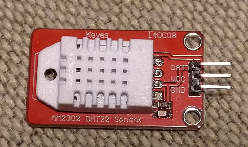
The location of the temperature/humidity sensor (DHT22 module) shown earlier is an interesting design decision. It is currently placed in the same location with the electrodes. However, there were no fastening mechanism designed for the temperature sensor, because there was supposed to be a 3D-printer part there held by electrode bolts carrying it. The part was not designed at the same time as the pool because there was no information about the size of the temperature sensor at that point.
Now the electrodes are insulated in place without inserting the desingned part. The better location for the sensor would probably be in the stand, if the stand is to be redesigned. The separate wiring would not be required then. However, if place in the stand it will be directly on the way of dropping water. The pool is currently wired directly in the stand without connector.
Note that the bottom of the pool is not covered with the rubber paint. Originally this was because it was easier to paint everything else first and the bottom last. However, it occured that with 10 % infill it would probably be a good idea that the water eventually penetrating inside the wall had some way to exit. So, I didn’t pain the bottom with rubber paint.
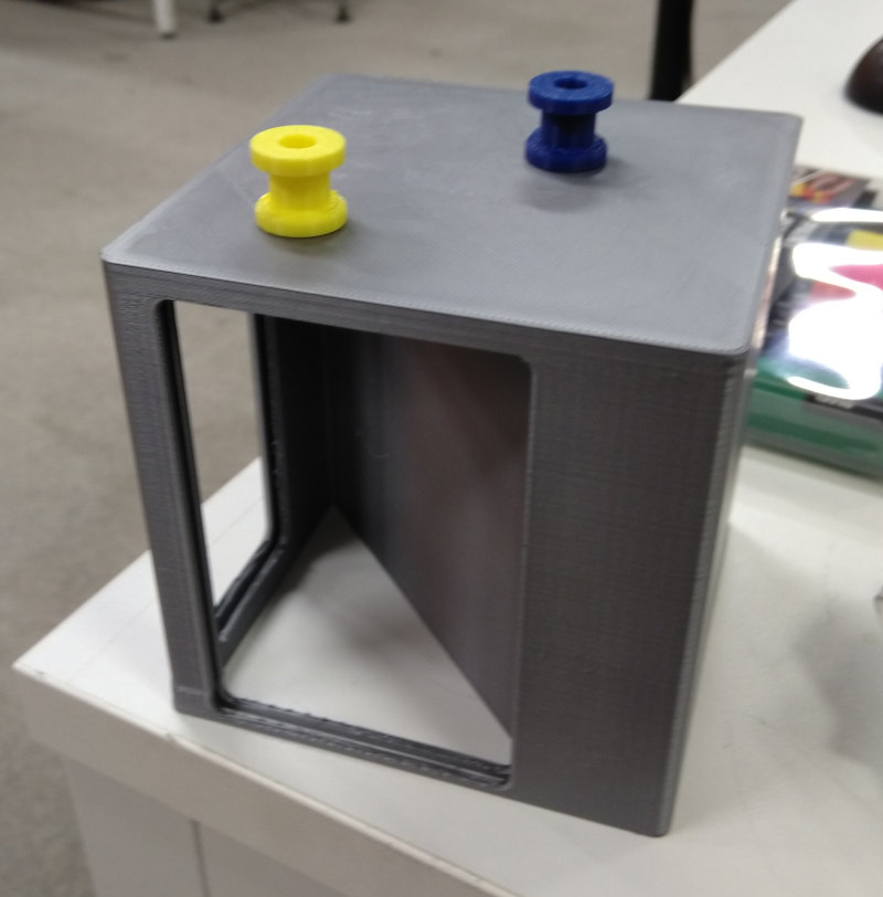
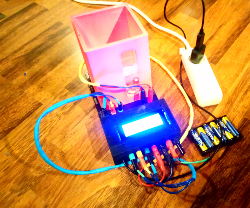
The pool and the stand form a functional combination which is connected to the control unit with four thick wires and banana connectors. Separate thick wires are used for structural support and also provide a possibility to use the pool directly without the control unit by just providing the current to the electrodes. The control unit has 10 A current limit because of the maximum recommended current for the 140C08 relay module. The pool/stand combination has no such a limitation.
Three of the wires are for the sensor and two for power. The connectors are color coded: Black and red are negative and positive terminals for the electrolysis current. Green is for DHT22 data, yellow is for DHT22 VCC and blue is for DHT22 GND.
The wires used for signal purpose are unneccessarily thick. For electrolysis current, they can’t be too thin, because the resistance leads to heat formation. However, it is often thought that electrolysis requires high current. That is generally true for any practical purposes, but my tests were powered with a set of 1.5 V batteries and they were just fine for the purpose.
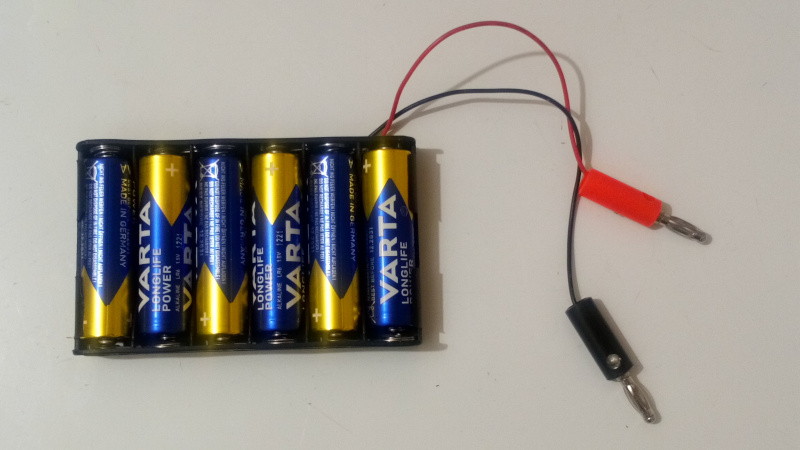
The pool produced gases just fine with the batteries. Video will be added later.
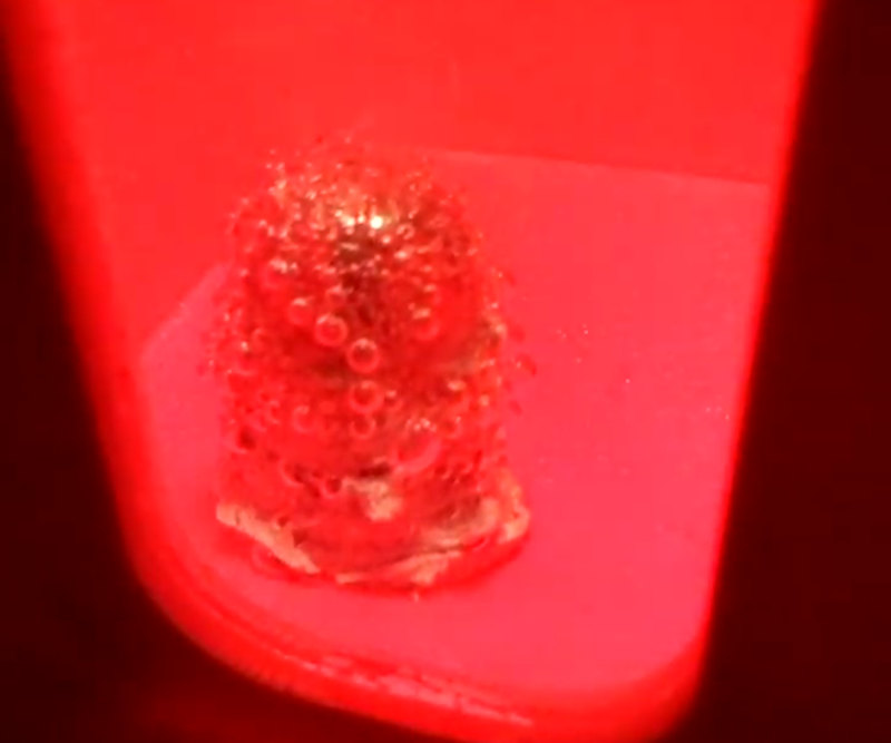
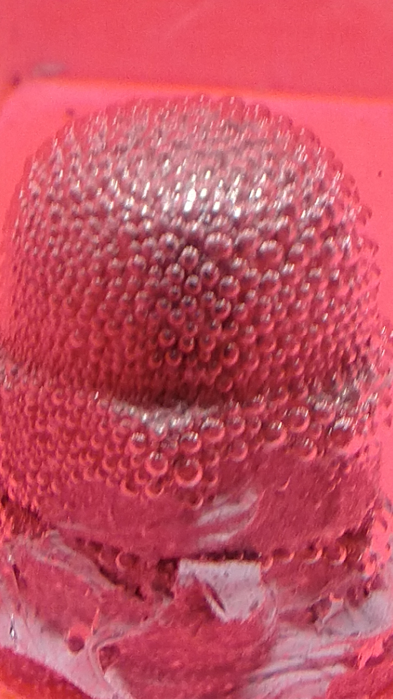
Closer view shows how the gas bubbles form on the whole area of the electrodes.
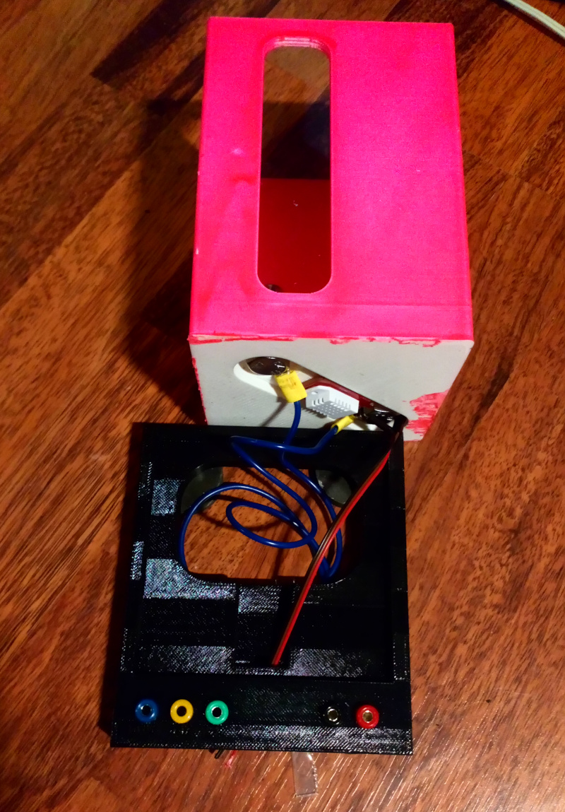
Pool stand
The pool stand was printed with Stratasys on black ABS (M30) together with the new version of the float. It was designed in Fusion 360. I used Fusion 360 repeatly for the weekly tasks.
The the Pool stand unit provide a way to pour the pool empty without hindering all the wires. Currently, it is still hardwired to the pool, but provides enough space that it is possible to pour the pool empty.
There are multiple design failures in the first version of the pool stand. The version used here is made usable by using the risers and removing some material below the connectors to make it possible to connect the wires. Too early version was saved for 3D-printing and some features, mostly extrudes, were missing from the printed version.
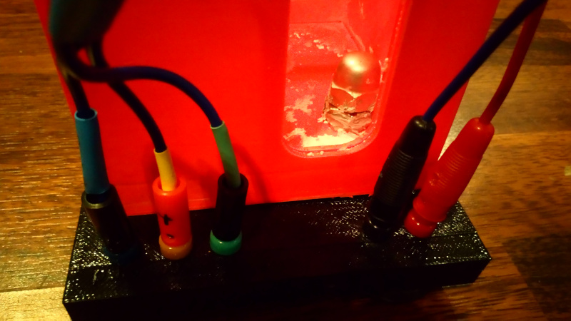
They were listed above in the What questions needs to be resolved-chapter. The genreral functionality it has is to provide three connectors for the DHT20 sensor and two power connectors for the electrolysis. All the connectors are color coded.
The blue connector is for DHT20 ground. The yellow connector is for DHT20 VCC. The green connector is for DHT20 data. The red connector is for electrolysis positive current, the black connector is for electrolysis ground.
The motivation for using banana connectors for this kind of laboratory experiment is mostly historical. The same type of connectors are often used in laboratory experiments done in schools. Also, there is a very real possibility of leak. Water leaking in a row connector might cause short circuit between positive and negative terminals easier. The banana plugs provide better protection from water by deflecting the water away the connector and rising the connector above the surface.
There are also four stands under the pool stand. They are just regular furniture stands used for protecting the floors.
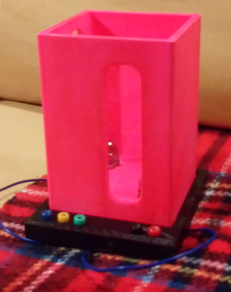
Control unit
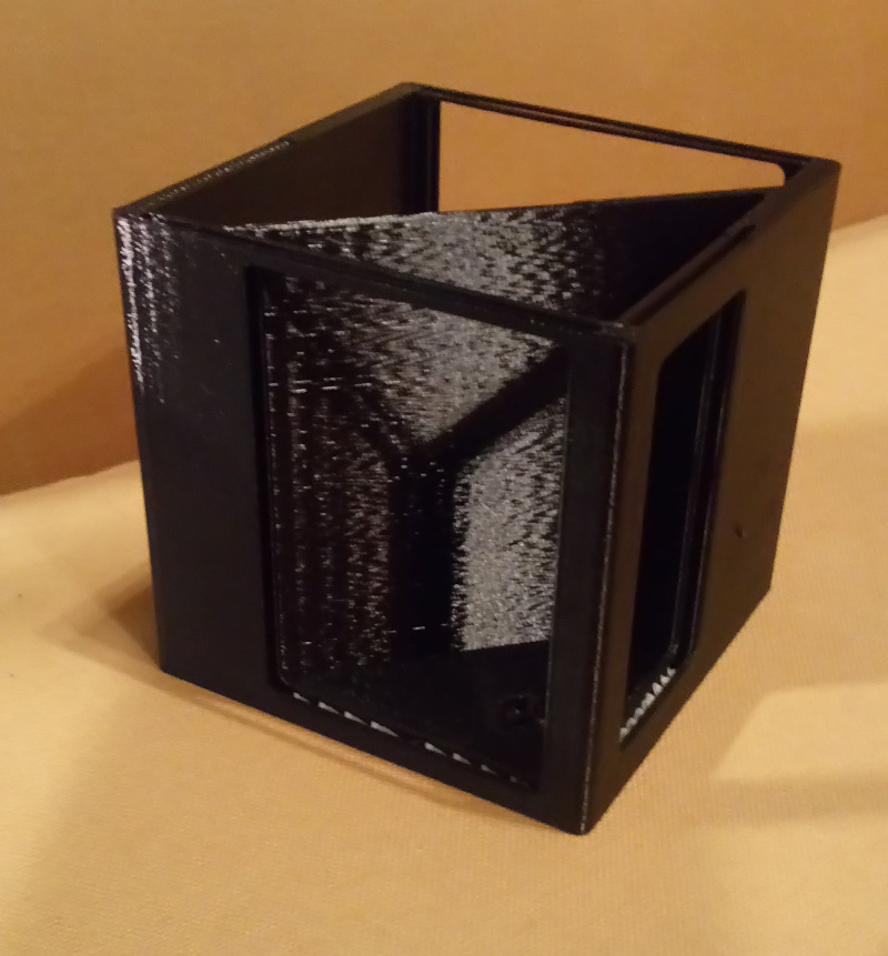
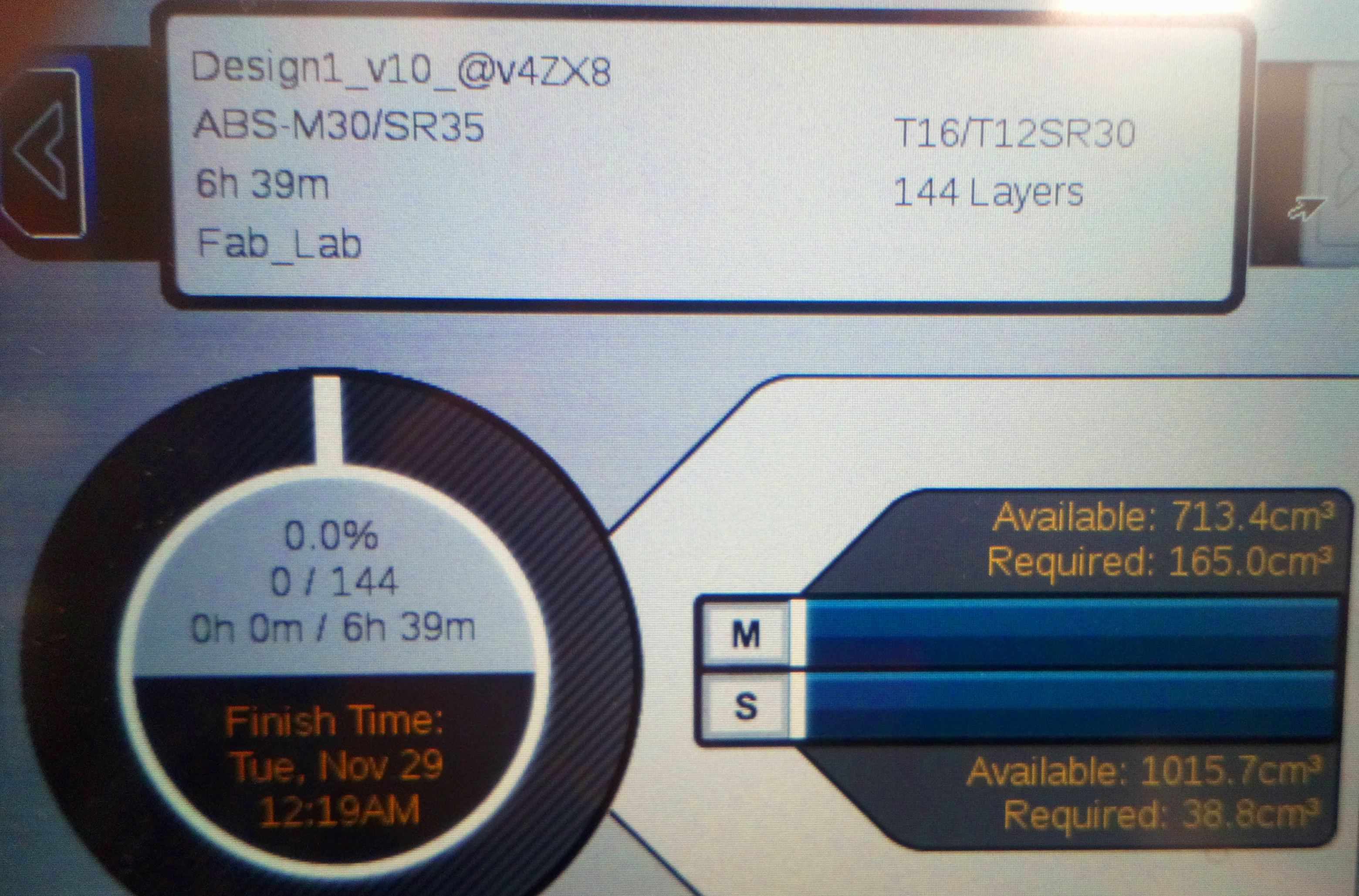
The control unit was printed on Stratasys on black ABS. 165.0 cm3 black ABS (M30) and 38.8 cm support material (SR35) was required. The printing time was 6h 39 min.
The case for the control unit was designed in Fusion 360.
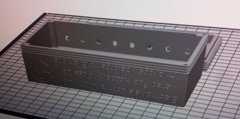
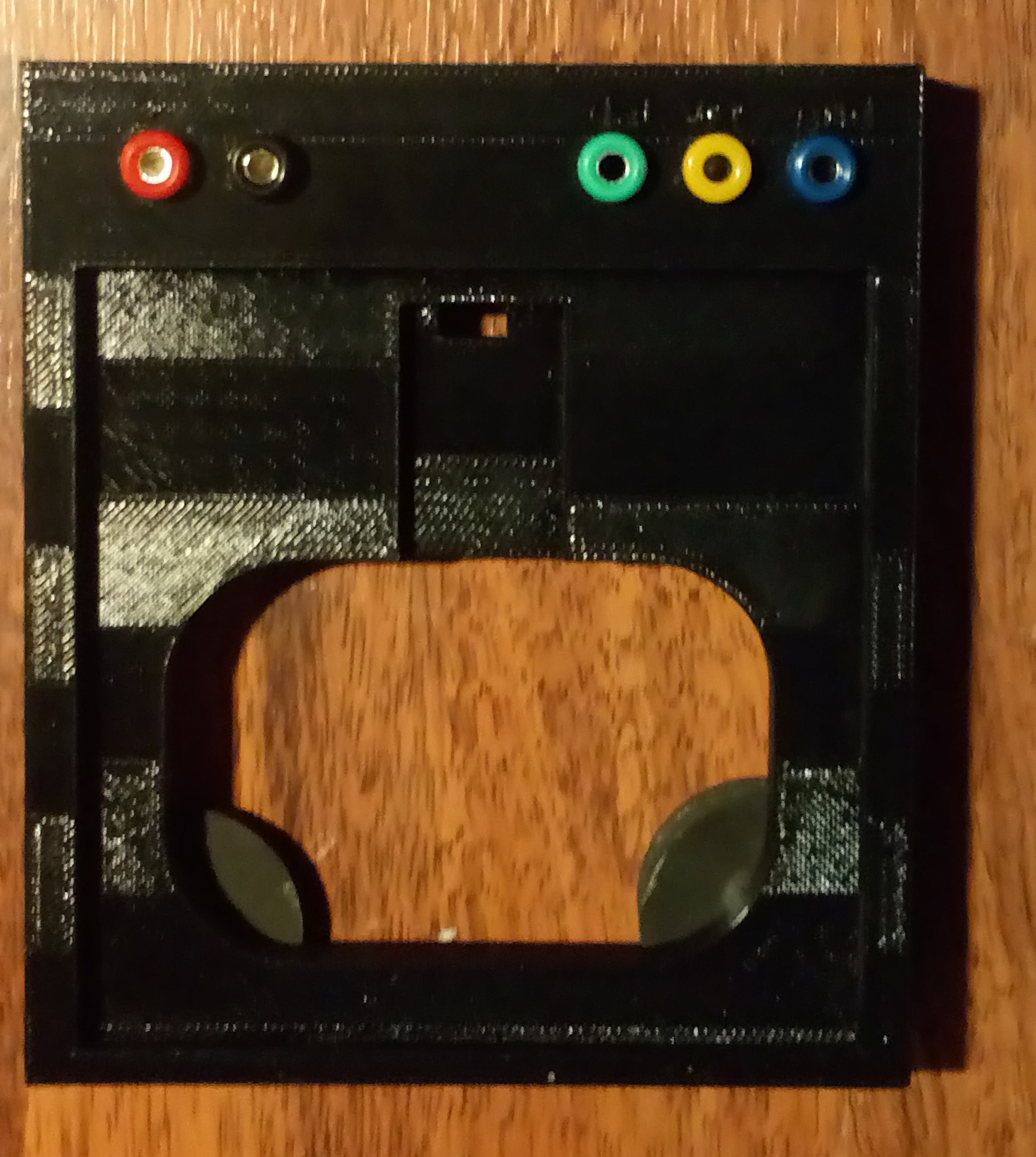
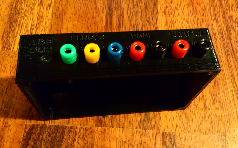
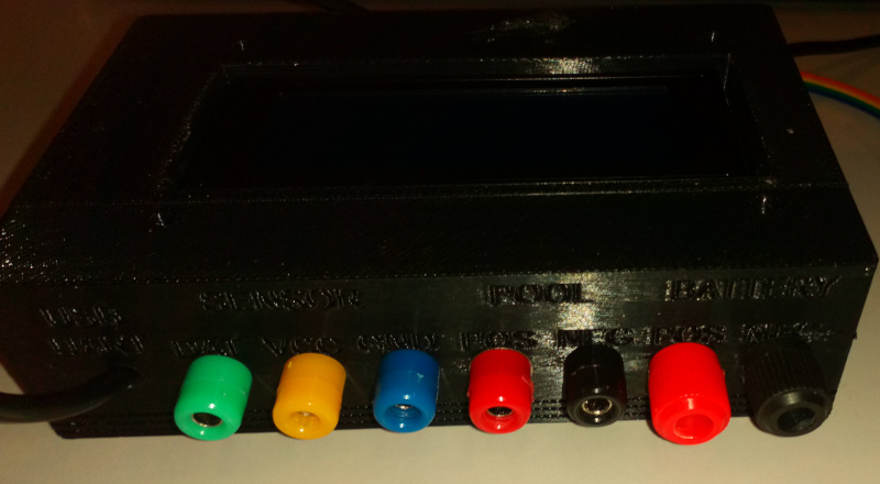
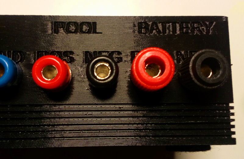
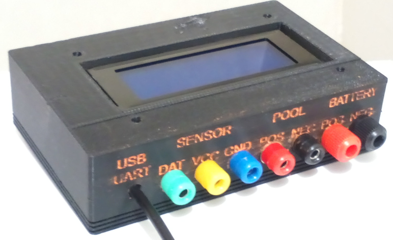
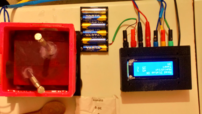
It consists of two parts. The bottom part and the top part. The top part is bigger and has holes for usb power cable (USB to UART converter cable) and the banana connetors for incoming electrolysis power, outgoig electrolysis power and finally three connectors for the external DHT22 temperature / humidity sensor module located in the Pool unit. Image from construction of the unit when the connectors were installed at the first time is shown below.
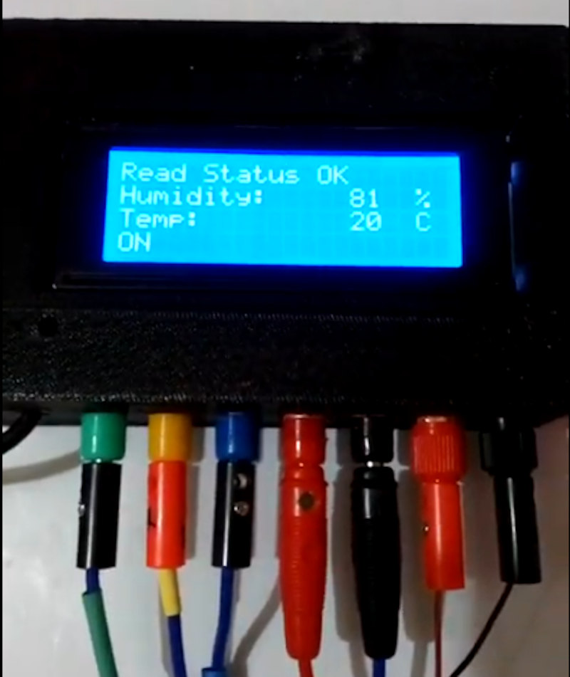
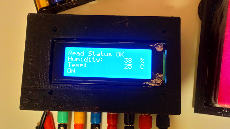
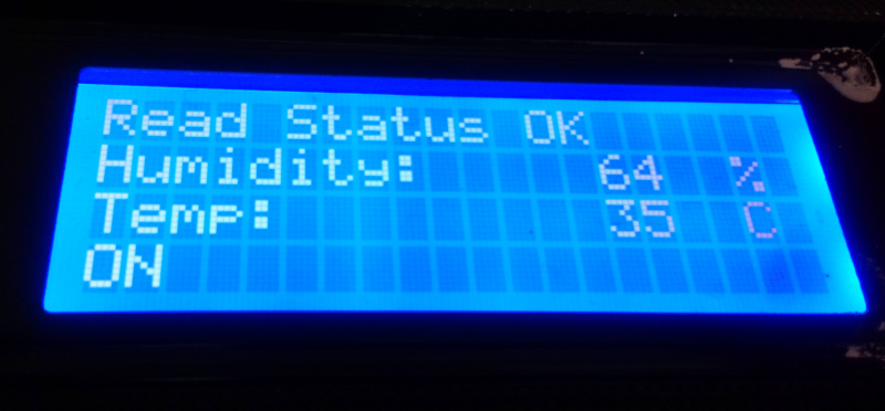
The control unit monitors the temperature of the pool and cuts the current if the sensor temperature rises above 35 degrees C. The control unit also displays if the connection to the sensor is ok or if there is an error. It also shows the sensor temperature and the humidity on an LCD display.
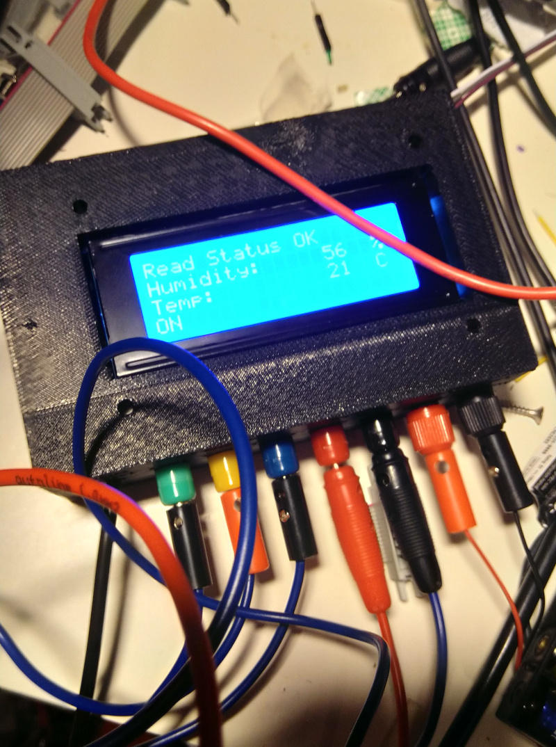
A better view to the LCD screen.

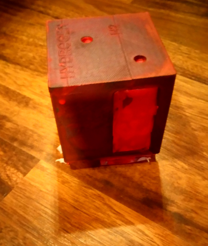
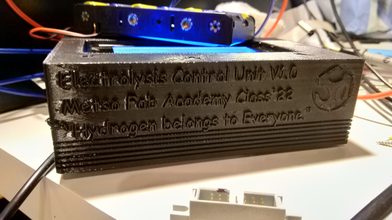
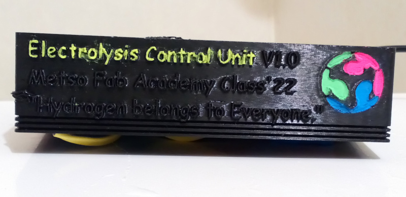
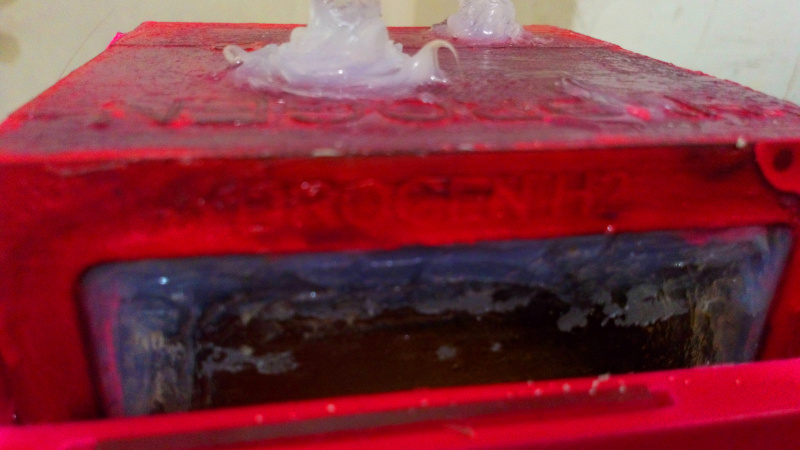
The back side of the control unit contains only some text and a nice logo.
The first version of connections between the control unit and the Pool are shown in the video. This was the first time the system was tested.
More work on the control box
One of the requirements of the Final project was that the wiring should be made properly. I made the wiring inside the control box and the wiring between the pool and the control box more compliant with the guidelines given. The separate wires between the pool and the control box were grouped in two sets, power set and sensor data set. All the wires on a set were combined. All the wires were color coded. Also the wire sets were colored differently in order to minimize the possibility of connecting the wires wrong but still maintaining the versatility of being able to use different pool, different power source or different sensor.
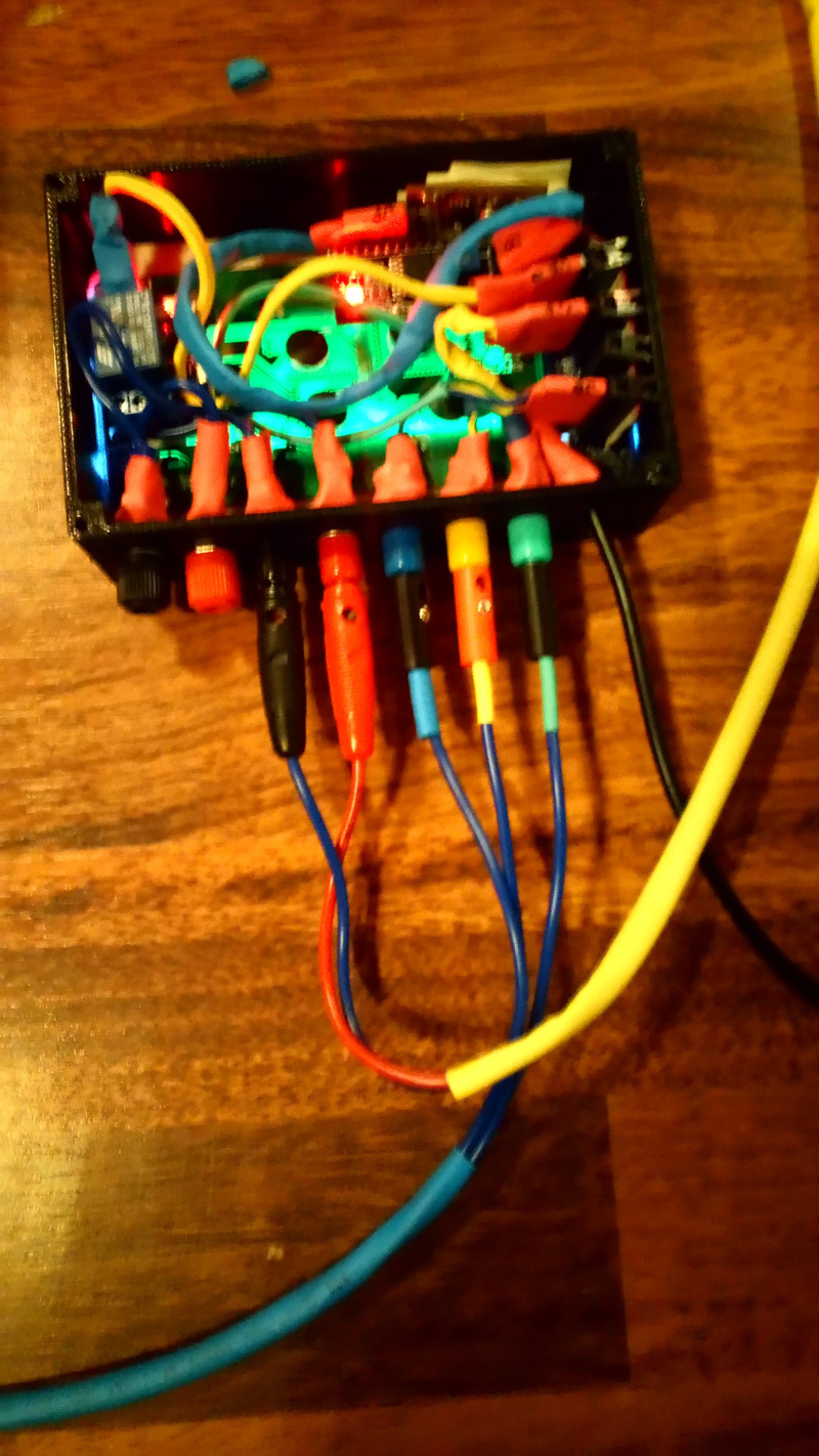
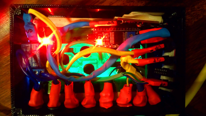
Inside the control box. the wires were grouped, connectors used and loose wires contained. There are three different cables inside the box, color coded with different colors. The power cord is also yellow, but probability of mixing it are low. The top direction is marked in every connector. The back sides of the front panel connectors are all insulated.
The connectors in the pool stand are color coded as well.
After tidying both the external wiring and the system looked like this.
More detailed view inside the control box. The red lights come from the LCD control circuit and from the 140C08 relay module.
Contents of the control box
The heart of the control box is the same microcontroller board that was designedby me on the Electronics design week. I made a new one for this project, but the connector broke off at testing phase. The one in use now is one of the earlier boards following the original design.
The left header
There are two six-row headers in the board. The right header has six pins. From top-down direction the pins are onboard LED pin, onboard Key Button pin, Free external connection pin, VCC, GND and UPDI data pin for programming the device.
The design uses the second pin (originally the button pin) for relay control. It is a logical pin 0 for the program.
The third pin is used for communicating with the temperature / humidity sensor (DHT22 module). It is a logical pin 4 for the program.
The right header
The right header is connected to the bus. The bus is a scaled-down version of the bus used in the Networking and communications week. The differences are shorter lenght, no male header and the row of pins connected originally to the left side of the microcontroller board is not connected.
The bus connected to the right header
The bus consist of about 4.5 cm of 14-wire flat ribbon cable. The cable was originally 16-wire,but two wires were removed for it to fit in 14-pin connectors. There are five 14-pin row connectors connected to the bus spaced so, that the bus has some flexibility. One of the connectors is not used by the system, but it can be used to program the microcontroller by connecting programming wire from the UPDI programmer to the bus. The programmer was the similiar to the one made on the Electronics production week.
One reason for using the bus is that it is also used for distributing power to the relay and to the sensor module. No separate power connectors or wiring is used now.
The power budget of the device
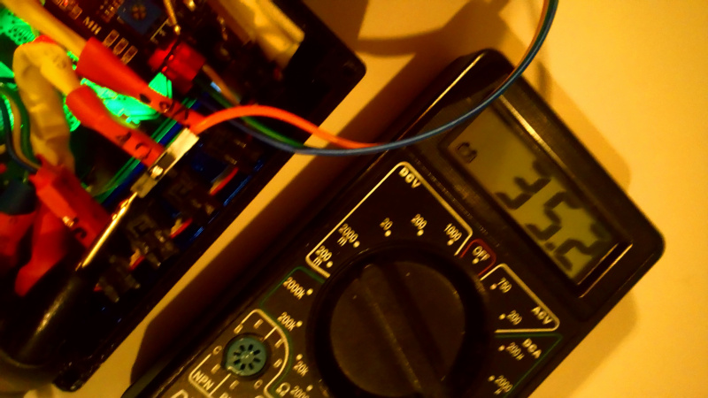
Can the ribbon cable be used for delivering the power and does the device draw too much power from the USB bus? DHT20 draws 3.2 mW. The coil in the relay module consumes 450 mW. The microcontroller using the same components consumes 55 mW (see the group assignent on the Electronics desing week. This totals 508.2 mW. The leds when turned on can consume a few tens of mA more. The display module had drived module connected to it, so I opted just measuring the current consumption with backlight turned fully on. The result was 35.2 mA. It was lower what I expected, but that is what was measured.
Calculating all the data with a P = U x I rule ( I = P / U), the full current comsumption of the device is 140 mA.
The microcontroller board using the same specifications draws 0.11 The ribbon cable has markings 28AVG. This tells the maximum current defined by the cross-sectional area of the cable. This table (external link) suggests that for chassis wiring the maximum current the cable can take is 1400 mA.
Also, the maximum current that can be safely taken from the USB bus is 500 mA.
The conclusion is that the ribbon cable can be safely used in this application and the current consumption does not exceed the amount of current the USB bus can safely provide.
External links: - The data sheet for the coil. - [https://aqicn.org/air/sensor/spec/asair-dht20.pdf]
The devices in the bus
In this design, the devices are connected to the right side of the bus. The bus is physically placed to top-down direction, the red zero wire is on top. There is no keying in the bus, so the top direction is marked in every connector in the bus with word UP.
The first device connected to the bus is the microcontroller card.
The second device connected to the bus is the relay module. There is a yellow cable connecting the bus to the relay.
The third slot is used for supporting power to the bus. It uses a yellow wire as well, but the power cable is easy to identify because it is connected to the USB to UART cable, mixing is unlikely.
A connector was placed on the head of the USB to UPDI cable and the data pins for serial data were placed inside the cover with the plastic one pin connectors still in place. If the device were expanded later, the pins can be easily connected to the free row in the bus for providing serial connectivity like in the Networking week.
The fourth bus slot is not used by the design, but is for programming the microcontroller without removing other devices in the bus. It can also be used as backup slot or for future expansion or for enabling the second row in the bus.
The fifth slot is used for connecting the connectors for the external DHT20 module to the bus. Green color is used to mark the cable. The three other ends of the cables are connected to the external banana connectors with round end tips. All the connectors are insulated.
The external connectors are color coded. Green means signal, blue means GND and yellow means VCC. For easier identication, the cables have the same markings and there are the same colors in the pool side connectors.
In the Pool side the wires from the connectors are directly wired in to the pins of the 140C08 DHT20 module. A three-pin row connector is used in the end.
The left header has also six pins. From top-down direction the pins are GND pin, a not-connected (NC) pin, VCC pin, Free external connection pin, Free external connection pin and the last pin is another not-conneted pin.
There is only one six-row connector in the left header, because it wasn’t necessary to connect a bus there in this application. The cable is color coded blue and it goes to the header in the LCD display control module. The order inside the cable just maps the connected pins in the left header (excluding NC pins) to the connector in the LCD control module, with the order of the two data pins swapped.
The display module used is the same I used in the Output Devices week experiments.
The electrolysis current circuits
The electrolysis current circuit is used for turning the power in the external Pool on or off. The ground is directly connected from the incoming black terminal to the outgoing black terminal. The external headers for incoming and outgoing power are different so they can be easily identified. There is also text in the control unit identifying the incoming and outgoing pins.
The 140C08 DHT20 module is connected between the positive terminals. The cables are connected to the first and the second slots in the screw connector from the left when facing the connector. These are the top and middle positions in the image.
When the program turns the logical pin 0 on the cpu on, the signal advances to the bus, to the yellow cable and to the relay activating it. The relay turns on, connects the pins containing the power wires on. The incoming and outgoing positive terminals are then connected together and the current flows to the electrodes of the pool. There the ions in the water (Glauber’s salt in this case) carry the current. The potential on the poles exceeds the decomposition potential of water leading to release of hydrogen and oxygen on the poles.
Testing the full setup
When the float was inserted into the pool filled with the water, it sank like a rock.
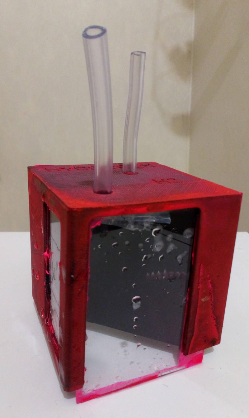
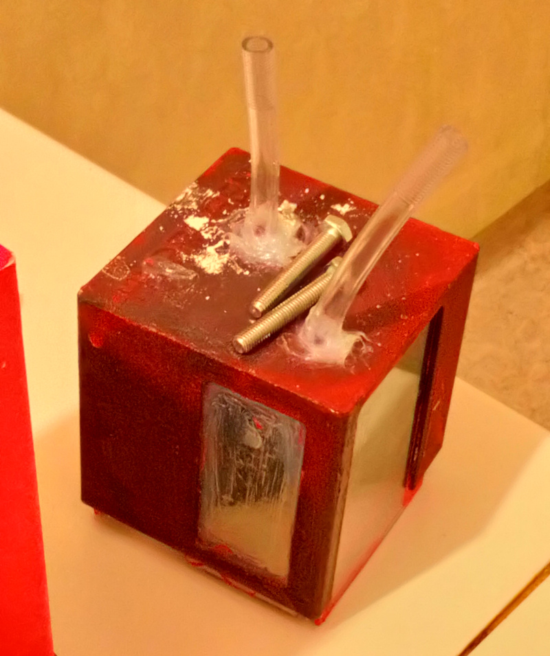
The tapes I had used for covering the holes were not airproof. I inserted shortplastic lines instead of them. The size of the lines was perfect.
Then I looked for a way to cover the ends of the pipes and I found one.
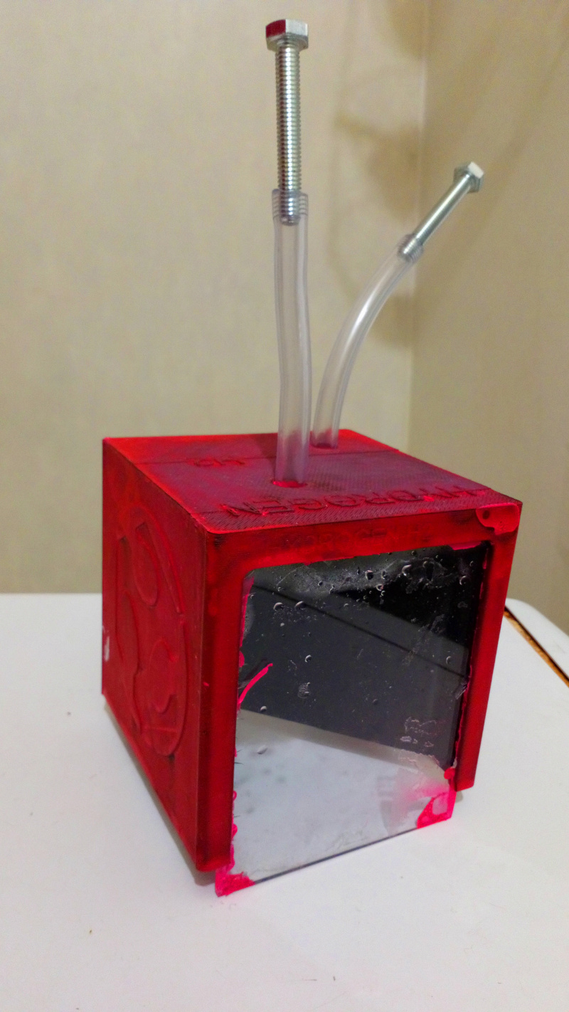
What happens after the hydrogen is produced, contained and a way to collect it is provided is beyond the scope of this project. Therefore just closing the pipes by now should be a viable alternative.
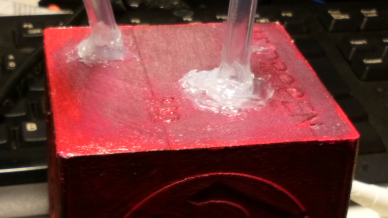
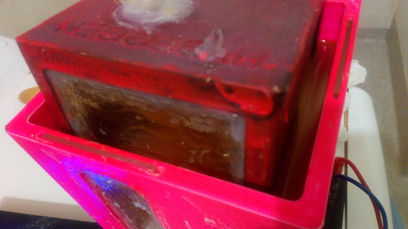
The new test was made to see, which places require fixing. It was obvious that the sides of the glass on N corner of HYDROGEN text and in the connections of the pipes needed some work.

The cube was already covered with rubber paint, so the silicone sealant applied on cube would be placed mostly over the paint. It should be easy to remove later if necessary. Casco Silicon was used for covering the leaks.

I like making estetically pleasing products, but this is not one of those times. Hydrogen is called the element number one for a good reason. It is the lightest element with very small molecule size. I covered the corners of the leaking glass with silicone sealant, with large margins. I applied silicone sealant over most of the hydrogen chamber outer sides and also on the top of the float. There was also a place where there was a bubble in the picture. I covered that position as well. I didn’t glue the pipes, which probably would have worked better, but applied a thick layer of silicone sealant around the pipes instead. Protective gear was used. I also had a hot glue gun ready for surprises.

While waiting the silicone sealant to dry, I painted some of the letters in the box to see if the paint I have works for it. It appears that the paint works.
When the silicone sealant was cured, after a few hours, there were no visible leaks on the hydrogen side. Unfortunately the side window in the oxygen chamber was leaking, so I fixed it next. I learned that next time I will cover all the window corners with silicone sealant right after assembling the cube. The curing takes a lot of time and it is always possible to remove the extra silicone sealant later. However, if the middle wall is holding, leak in the oxygen chamber would not stop testing the hyrgoten side.
After the silicone sealant was cured, the float didn’t leak anymore. The setup was quikly connected and ran.

The humidity sensor showed 81 %, indicating leak in the pool. Soon it became obvious, that the leak rate is so high, that the pool will be empty soon. So, it was time to dry the pool and apply silicone sealant to it.
The pool was dismantled and silicone sealant applied to window frames and electrode connections. It needed to cure.
After the pool was cured, it was still leaking. I decided to run against the time and filled another battery pack. However, after measurements, the pack provided 5.69 amsp at 5v, so using 2 packs in paraller would exceed the 10 amp limit.
It was now obvious to me, that this game was lost at the time, when someone who helped me in the Fab lab selected 10 % fill rate for me. Reprint on abs / with other than lace like fill rate was needed. However, it was still possible to use this pool as proof-of-concept design-
I got an idea of the Molding and Casting week. I ended up burning more money and buying Sika silicone sealant and Gorilla tape.

I used the tape as a mold and filled the mold with Sikasil silicone sealant. The general idea was to make so thick layer of silicone sealant, that it just can’t leak. Also, I already had used Casco silicone sealant and using silicone is a kind of one way: It is a common knowledge among the people who have ever painted their own car, that any common paint just won’t stick over silicone products. I didn’t include the temperature sensor, because it can be temporarily fastened in the side of the pool. In the next version this could be a default way to do it.
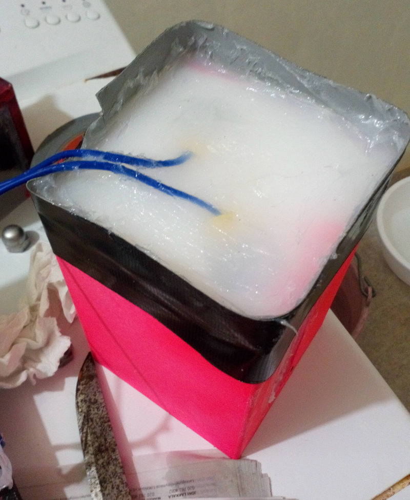
Because of the mass of silicone sealant, it took until morning to cure. However, this time the pool did not leak. If leaking water is inherent feature for 3D printed objects, it might be a good idea to design the pool for silicone sealant from the beginning. That would include using more waterproof acrylic, designing all the printed material to be covered with silicon from the beginning and minimizing the area any 3d-print contacts directly with water. Also the window openings should be made so thick that there is room for acrylic sealant between the acrylic and the print or just design some space for the sealant to cover the window frame from the beginning.
The gorilla tape frame did not result in even floor. Harder frame would have done it better.
There is also white silicon in the floor of the pool. The electrode tips were easy to screw on their places, because the soft silicone sealant on the way of the tips just moved away.
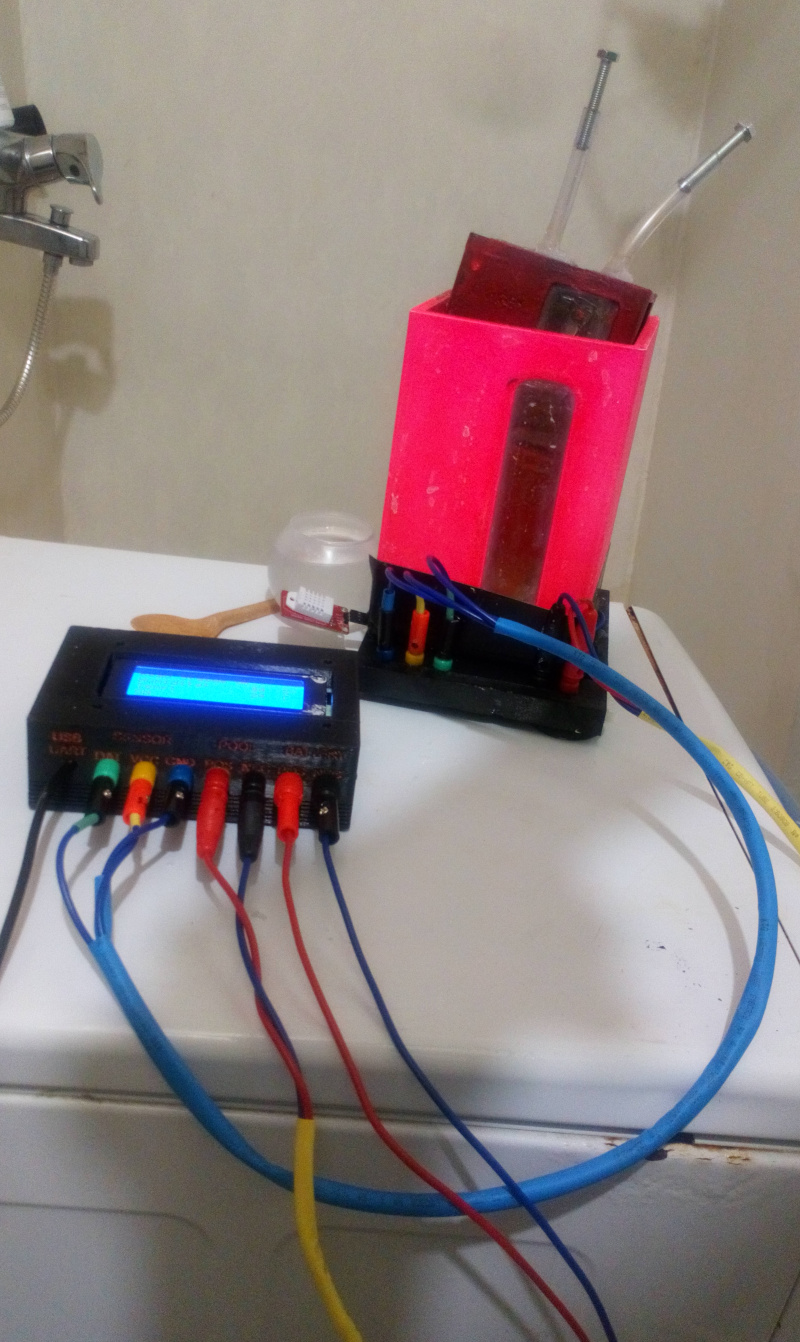
Then it was time to test the system again.
The system was set up and the pool was filled with water.
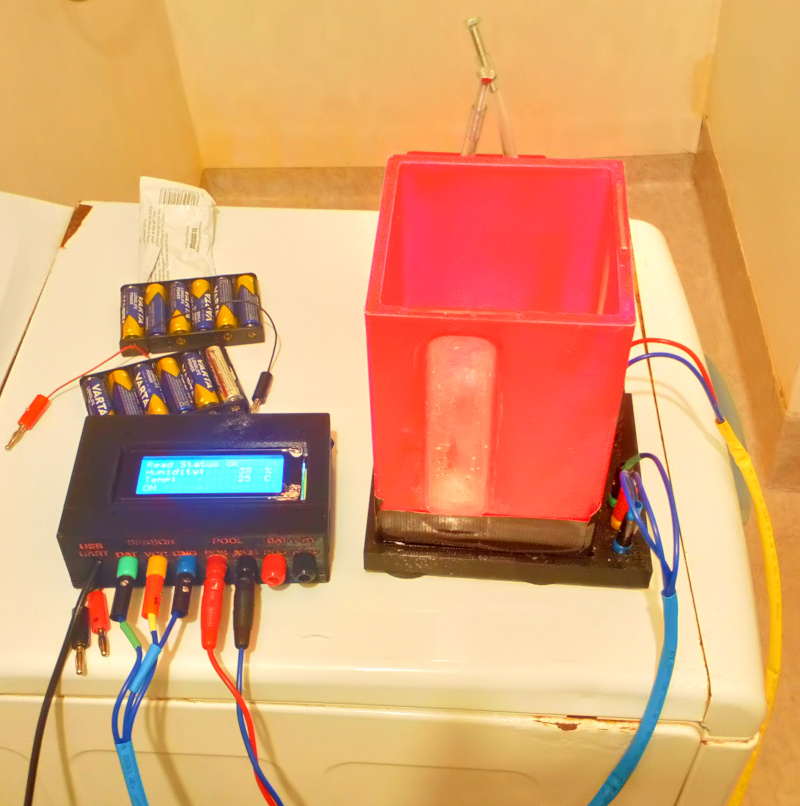
The control box was fully operational.
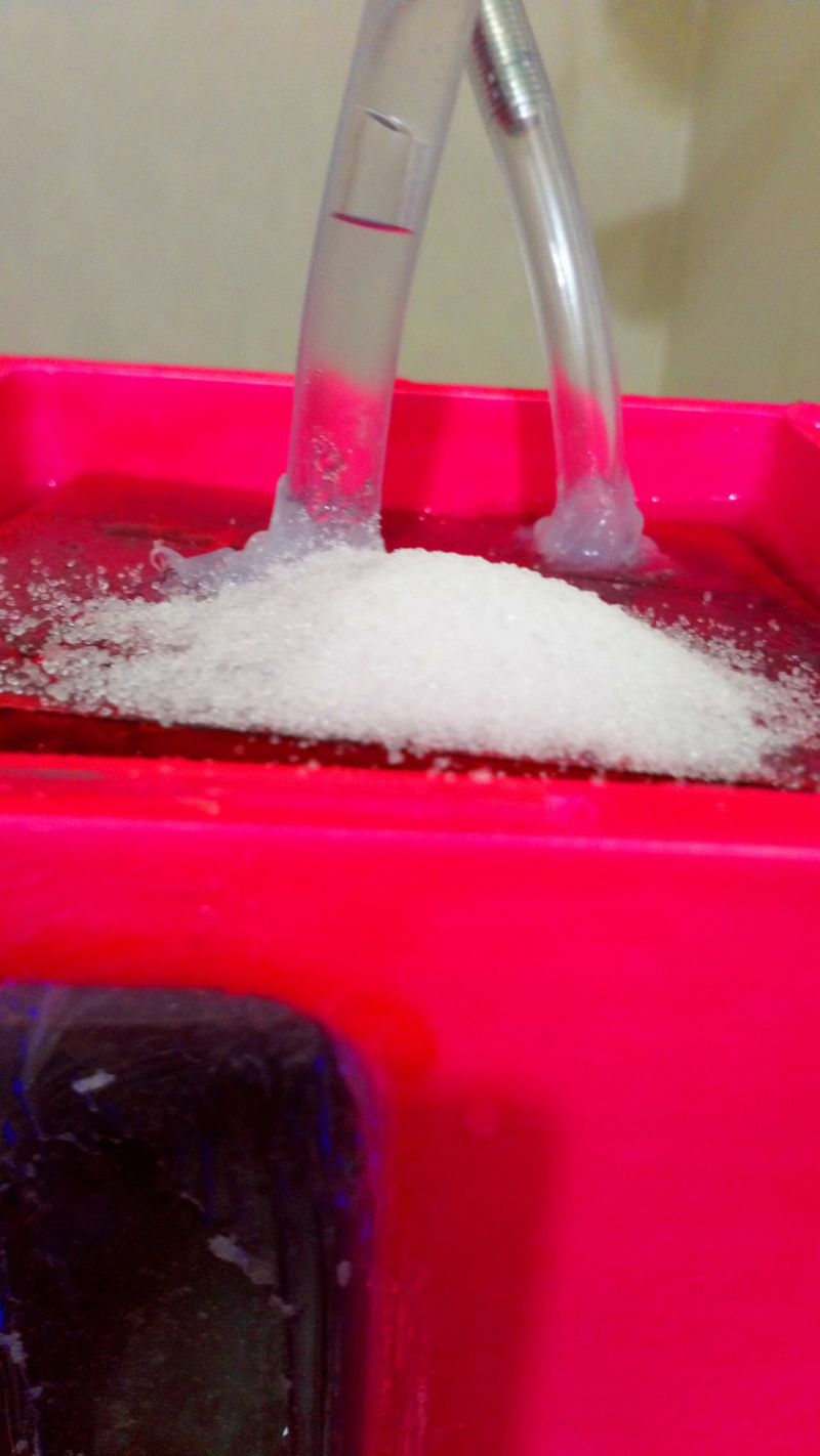
Glauber’s salt was added and it dissolved to the water.
The float was ready.
The float was placed into the pool and it slowly sank to the bottom of the pool.
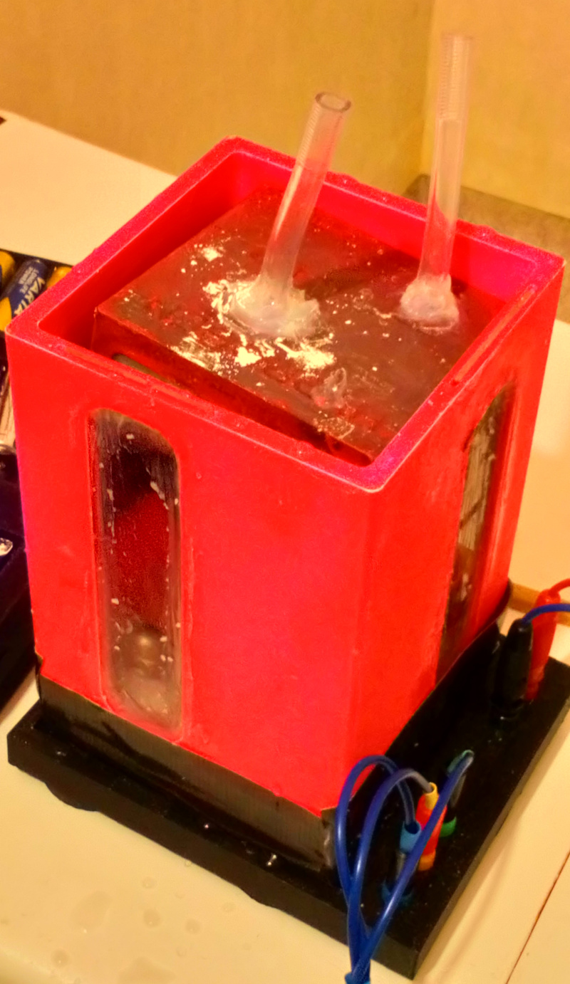
The lines were blocked so that the gas will accumulate inside the float.
The power supply (battery pack) was connected to the control box.
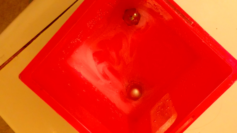
Bubbles emerged on the electrodes.
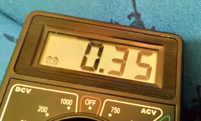
At this point the current flowing through the circuit was measured with multimeter. 0.29 A was measured. This was a very low value. The battery pack can provide 6A.
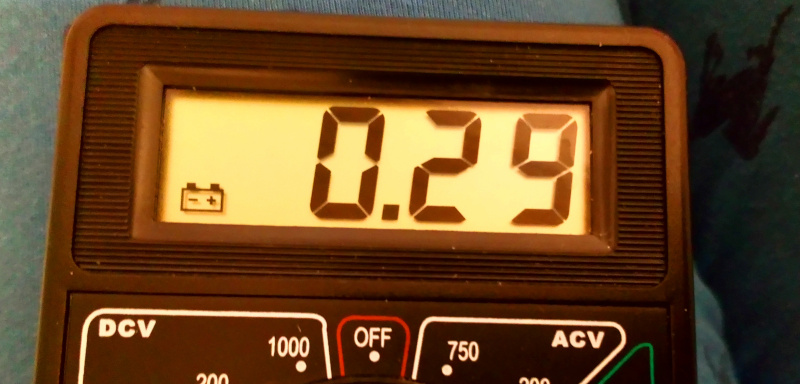
The rest of the Glauber’s salt was added. Note the threads appeared inside the lines and the water in the pipe staying in the same place indicating that the pipe doesn’t leak.
The measurement was repeated after the Glauber’s salt was immediately dissolved in the water. Apparently the current would increase more if more Glauber’s salt were added. We were fine with this amount of salt.
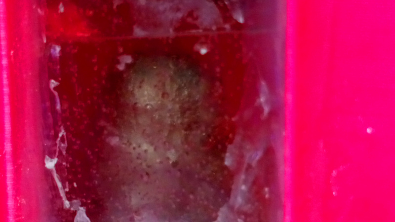
The gas started slowly accumulate inside the float.
At this point I felt pretty confident, that the 10 A limit of the relay would not be exceeded and changed the power supply. I also trusted the isolation I made for the 12 V side. Wires were made and 35 Ah battery capable to *300 A output was installed.

The gas output increased considerably.
The float very slowly rose, while the gas accumulated. 90 % decrease in size had the problem with window thickness. The another problem appeared to be that it had room to tilt a bit. This would decrease the amount of gas the float can hold a bit.
It was time to test, if temperature limiter (the input device in the final project) worked. The sensor was removed from the bottom of the pool (which was insulated by a thick layer of silicon anyway) and warmed with some hot water.

At 35 degrees C the relay was ON.
At 36 degrees C the relay was OFF. The result was also confirmed by observing that the gas output ceased immediately after that.

So, the temperature sensor input worked, the relay output worked.
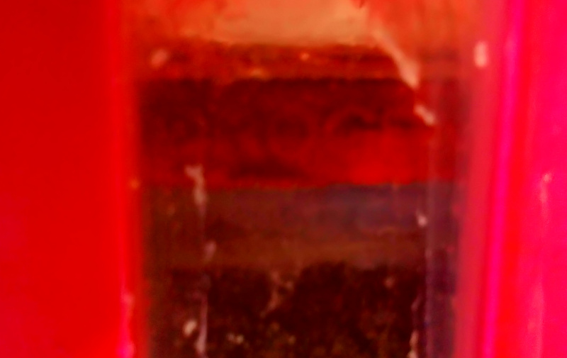
The hydrogen gas was generated and stored.
Also the oxygen gas was there.

That would confirm that the general objectives of this final project from my part were achieved. Now it is only a matter of rising the quality of work to the level accepted by evaluators, most likely on the next evaluation round. I would also assume, that the most important problems in the design should also be fixed, new updated models printed and tested as well.
In my Application and implications week documentation I set the evaluation criteria for the final project:
- 1) Does it produce hydrogen or if that fails, HOO gas? 2) Can the gas produced be collected in order to see if the system actually works? * It was already established, that the gas can be produced and collected. Now there as only one question left: Was it really hydrogen I produced? This still needed to be confirmed.
In my Principles and practices week documentation as well as in my IPR week documentation I discussed about various properties of hydrogen gas. So, it was quite obvious how to test, as required by the if the gas really was hydrogen.
I didn’t have access to chemisty laboratory, where I think I have actually identified hydrogen in one of the chemistry lab courses I took. So, there was only one sure way to find out.

When the pool and the float exploded loudly, I had finally confirmed that I had produced hydrogen and my Final Project had succeeded.
My global evaluator had already told, that I had missed the December the first deadline, so I have plenty of time to 3D print the new one before the next summer, if I can afford to finish the Fab academy then.I was already told, that there will be costs associated to graduating then.
I already provided links to improved designs for some parts earlier here. The float obiously needs to be a bit larger so that it doesn’t tilt (98% of the original instead of 90%, I assume). The pool should be updated so that there is planned room for the silicone sealant.
The control box and the wiring is fine, by the way. It contains input, when the sensor is connected and output in the form of relay and LCD display.
What isn’t fine then? Well, document as you go:
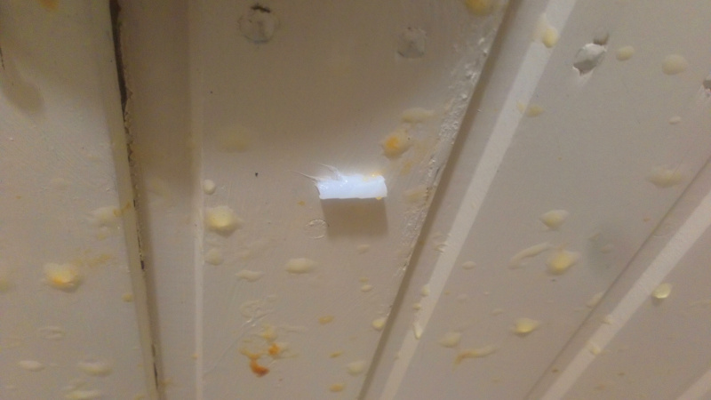
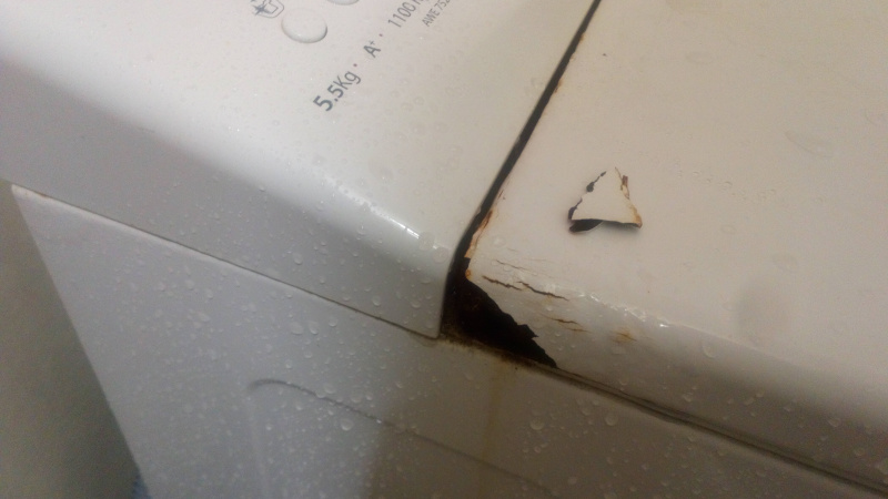
The roof had to be cleaned.
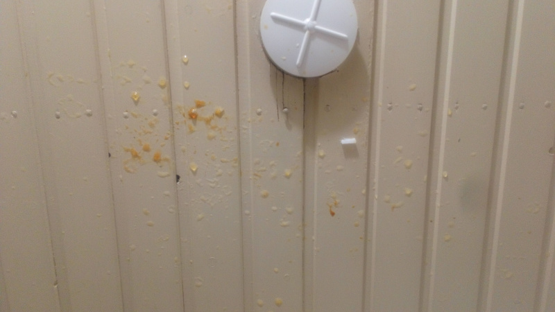
Note the piece of silicone sealant still stuck there.
There was obviously rusty water everywhere to wash out before it sticks. Some acid proof iron had dissolved to the water, so changeable electrodes probably were a great idea.

A piece from the washing machine I used as a lab desk was broken off. There was rust under the paint, so piece of paint fell off. I have planned to repaint it properly for a year now, perhaps I have time to do it after the Fab Academy is finished?
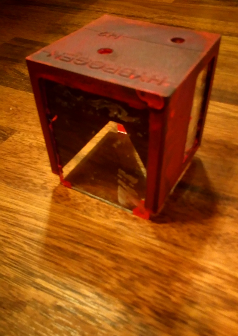
The float had exploded and obviously needed some tender, love and care. Or perhaps a reprint. The acrylic had shattered.
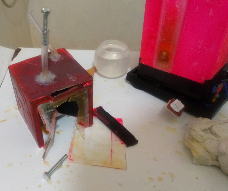
The corner of the pool was cracked, probably because of that 10% fill rate. The windows had so thick layer of silicone sealant on them, that they survived.
Also note the direction of the explosion (from bigger side) and compare it to which side of the pipes is open (the smaller side). Apparently there was at least some hydrogen on the oxygen side. The float itself did not leak, because no bubbles emerged when the float was pushed under water.

Thank you for reading. I can sincerely recommend Fab Academy to everyone. I obviously still have lot to do to graduate some day.