17. Applications and Implications
This is a short reply to the questions.
What will it do?
My product is an water electrolysis chamber for producing hydrogen. It will break down water to hydrogen and oxygen in order to capture hydrogen. The input of the system is water and electricity, the output of the system is hydrogen. The waste product in the system is oxygen.
From the system point of view, the device will connect electrolysis current (can be calculated from the Faraday’s laws of electrolysis to the solution. The solution is mostly water with some Glauber’s salt. It is an input material of the system. The physical part of the device will provide a mechanism for containing the electrolysis solution and collecting the product gas (Hydrogen). The gas is ouput material in the system. The control part of the system will control the relatively high electrolysis current and provide some information of the process.
To simplify, it will read key inputs, measure something and display state and information derived from the data.
The system diagram is shown below.

The principle of electrolysis is shown in fablab.green. Note that in order to work properly as long term solution for producing hydrogen, a semi-permeable membrane is required.
Who’s done what beforehand?
In a theory level the product is a common demo in any high-school chemistry teaching. It was first demonstrated in 1789 by Jan Rudolph Deiman and Adriaan Paets van Troostwijk.
In my learning process, the idea was described in my Final Project page. I also did some design about the possible model for electrolysis chamber, expanding by the pressure of the gas collected, in the Computer aided design week.
I reviewed links about related projects on my Week 1 documentation.
I also documented experiments in my Invention, IPR and Income week documentation.
Hydrogen production has been considered at least in the Green Fablab.
Video links with comments
Shows that it is possible to fill candy balloons with helium. Why not with hydrogen?
Shows how hydrogen bubbles are made and how they burn.
Shows how hydrogen soap bubbles explode.
Shows how easy it is make a HHO generator.
Advanced design for HHO generator.
Simple design for HHO generator.
Wire HHO. Hydrogen Generator 316L Wire. Fuel from Water.
Other designs for electrolysis: Wire HHO generator.
Making of pulled sugar. This could be filled with hydrogen.
Making bubbles from other materials than soap.
Other useful links with comments
Properties of Hydrogen. Helps to understand how to handle it.
-
6. PROPELLANTS A. GENERAL FEATURES OF ROCKET PROPELLANTS.
Hydrogen could also be used as rocket propellant, but there are problems.
-
HYDROGEN PRODUCTION AND DISTRIBUTION.
How to distribute hydrogen.
-
Is compression of hydrogen a valid idea to store it?
-
Basics of electrolysis of water.
What will you design?
I will design a system based on the water electrolysis process for producing some hydrogen gas. The system consists of mechanical part (water and gas container), power part (1.5 V, producing current for water electrolysis) and a control part.
What materials and components will be used?
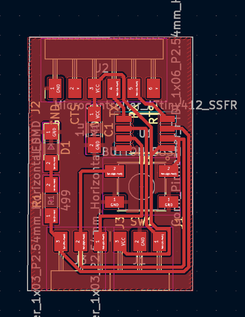
As a microcontroller, I will use the same design I already did in the Embedded programming week. The display solution will be the same as in the Output week.
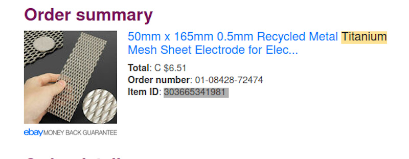
For electrolysis specific materials, I planed to use titanium grid for anode, perhaps for cathode as well. Titanium grid can be sourced from eBay.
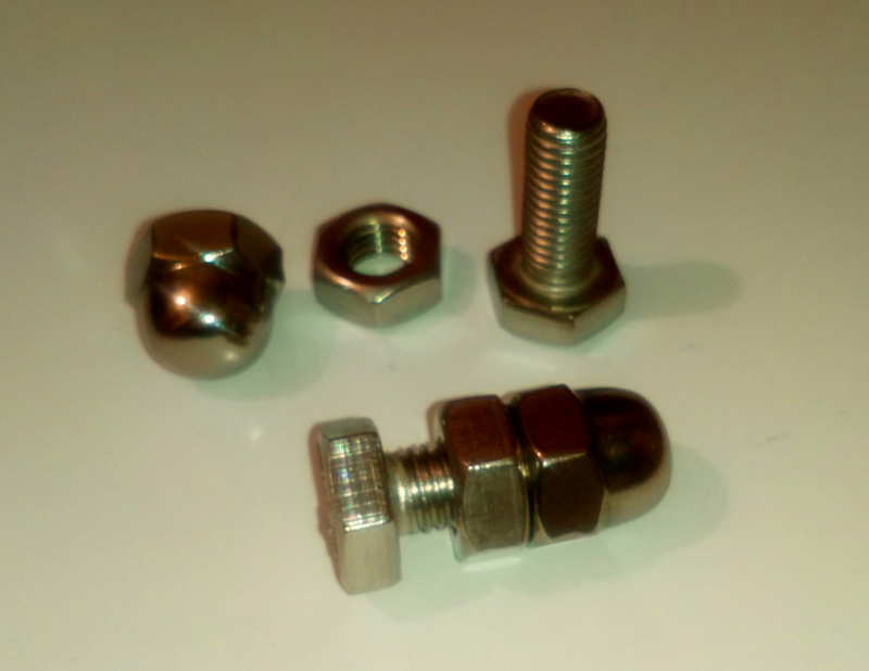
Acid-resisting steel seems to work well enough for this purpose. It can also be sourced locally from the local Bauhaus store. The store can be found [here}(https://www.bauhaus.fi/info/tavaratalot/oulu) and the driving instructions to there here.
Electronics built in FabLab. The basic central processing is done in a modified version of the same system already built. The modifications for adding the LCD module will be included.
The power handling for the electrolysis is another new feature required.
The option A is to create a regulated 1.5 V voltage with low current for electrolysis and a measurement for temperature. However, according to my measurements the increased voltage will provide faster results, so perhaps just using 5.0 V already available from the electronics would be sufficient.USB-C could provide a lot power. Option B is to use a small 12 V car battery and control high current with relay or a power transistor. Car battery would allow faster electrolysis and it would mimic the use of solar power system as a power source.
Water will be consumed in the process. There are no plans for adding water during the process. The process will end when the water runs out.
Where will they come from?
I already ordered and received the grid. I also bought the bolts of acid-resistant steel. Other case components will be 3D-printed or lasercut from acrylic. The case desing will be based on the one I cut in Egg Painter Project. I will use extensively materials available in the FabLab, 3D printers and acryl for laser cutter. The calculations and design for determining the dimensions of the device have not been done yet.
How much will they cost?
I estimate the price of the desing to be less than 30 euros, depending on the compontents and size. In order to do the electrolysis properly, a semi-permeable membrane is required. Ion exchange membranes are really expensive. However there are ways to manufacture the membranes. The obvious way to manufacture the membranes would be 3D printing suitable materials in the right configuration in order to let the water move but keep the larger ions on their sides. In spite of the inventor of 3D printable cheap ion exchange membranes becaming quickly a solar energy billionare, that is out of the scope of this project.
The price of the other components used from the FabLab stocks will be calculated later when the dimensions are agreed on. The target manufacturing price for the system is 30 euros.
What parts and systems will be made?
Pool (challenge to make it a way to capture the gas, there is a simple way and perhaps a smart way), electrolysis wires including anode and cathode, electronics for regulating the current and displaying the current/voltage (LCD).
One prototype was 3D printed. The system consisted of 2 parts, inner part moving inside the outer part. Pressing the inner part down would make the electrolysis solution pressurize the gases produced in their separated chambers. After pressurization, the valves would be used to collect the gas.
The 3D printed solution was a failure, because the structure was no waterproof. I tried to use paint to make it waterproof, but the tolerances were not designed for it. Therefore, a radical re-design is required.
Then there is also a question how to release the hydrogen when needed (valve?) or if it is simply let flow to an external container.
What processes will be used?
Laser cutting and 3D printing for the containers and electronics design and production for the electronics.
What questions need to be answered?
How to collect the hydrogen and leave out the oxygen. The main question for me has been for a while, how to separate reactions. It is easy just to collect the gases. In theory it is possible to use an ionic bridge, something that lets water go through but separates larger ions. Why I need the bridge? It would allow a pressure gradient between isolated andode and cathode chambers connected by an ionic bridge (semi-permeable membrane). Using an ionic bridge would make it possible to just release the oxygen and collect only the hydrogen.
The isolation of the reactions might not be necessary after all.
If an ionic bridge is found, the hydrogen generated would replace water in a chamber and it would be let out from the top of the chamber so that water replaced by the generated hydrogen would push the gas out by using the hydrostatic pressure. This can be done without the bridge, but it is more complex and perhaps unnecessary tall design then.
The sketch will be added here later.
How long can it sustain the reaction?
How will it be evaluated?
1) Does it produce hydrogen or if that fails, HOO gas? 2) Can the gas produced be collected in order to see if the system actually works?