13. Input devices
The group assignment of this week is here. I attended this weeks group assignment remotely because of COVID-19.
In my final project I am going to need a temperature sensor for measuring the temperature of the electrolysis pool. This week I decided to measure temperature with the board I designed earlier.
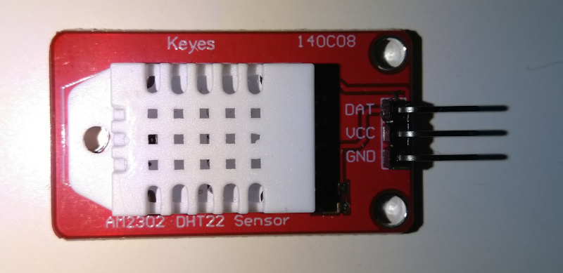
I decided to use Keyes AM2302 DHT-22 Module as hardware for measuring the temperature. Because the sensor also measures humidity, it was measured as well.
DHT-22 module.
DHT-22 sensor can measure temperature between -40 and +80 degrees C within a half degree accuracy in the environment we are going to use it. The sensor is going to be used for monitoring the temperature of the electrolysis pool. For that purpose the accuracy is sufficient. The sensor is temperature compensated and calibrated at the factory and no calibration is required. Because every sensor is calibrated at the factory, the sensors are also interchangeable.
The sensor can use operation voltages between 3.3 and 5.5V DC.
The DHT-22 module is shown in the picture below.
Installing the DHT sensor library
I evaluated a few sensor libraries. I couldn’t read the sensor data with TinyDHT or Adafruit DHT libraries. However, DHTstable library worked.
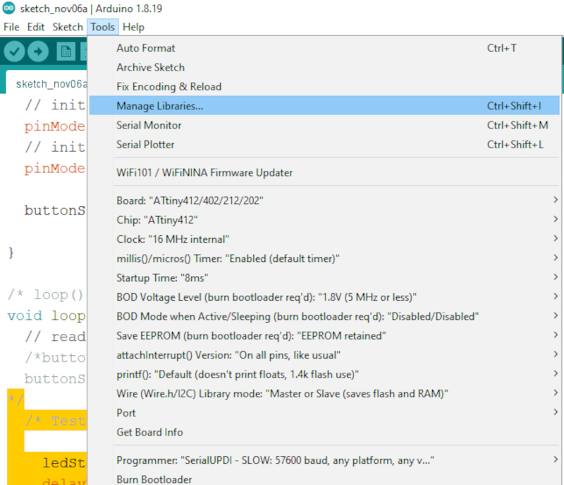
The installation procedure for DHTstable library requires opening the Library Manager in Arduino IDE and installing the library from there. The process begins by going Tools -> Manage Libraries.. in the Arduino IDE.
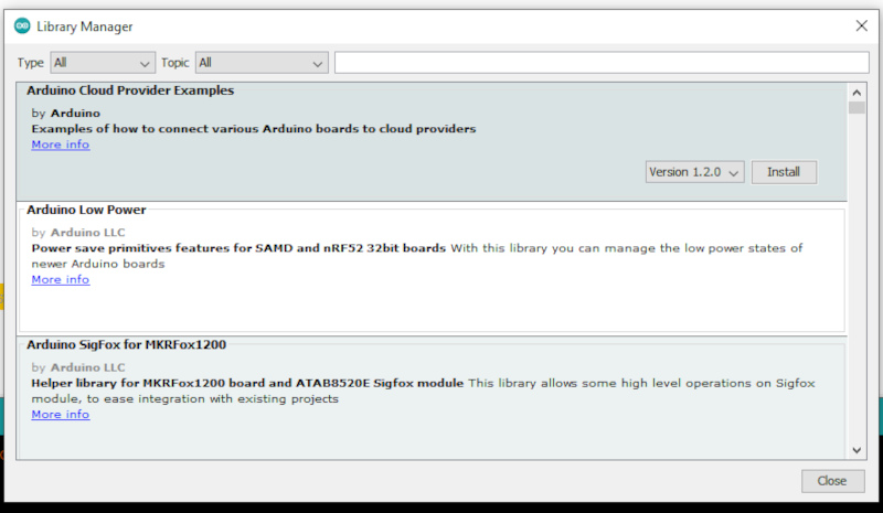
The library manager updates the descriptions and opens.
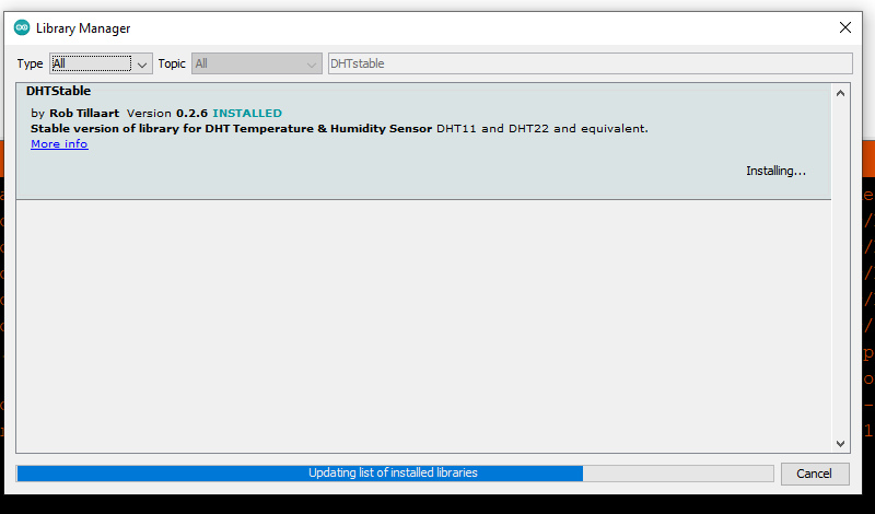
The search word DHTStable was typed to the search and the library is found. I clicked install and the library was installed. I tried different versions and the image is taken when the library was being uupdated to thge current version.
The library was installed and the list of installed libraries was updated. I pressed close to close the window.
Reading the sensor
In order to read the sensor, it was necessary to determine the physical connection of the sensor to ATtiny412. The diagram of the pins and names used for the pins is displayed below:
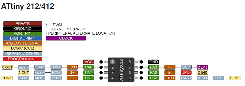
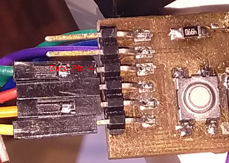
I wanted to use the LCD display to display the temperature and humidity. I evaluated the available pins and decided to use data pin 4 (PA3). The pin was connected to the chip physical pin 7.
I observed the DHTStable documentation (examples page)[https://github.com/RobTillaart/DHTstable/tree/master/examples]. I found the examples how to initialize the sensor, read the sensor and how to interprete the error codes. I also used my work on Output devices week as a base how to print the results to LCD display.
The code is shown below:
/* Antero Metso the 6th of November 2022 */
/* Input Devices Week */

#include <Wire.h>
#include <LiquidCrystal_I2C.h>
#include <DHTStable.h>

LiquidCrystal_I2C lcd(0x27,20,4);  // set the LCD address to 0x27 for a 16 chars and 2 line display


#define DHTPIN 4  // DHT connected to Arduino Uno Digital Pin 4 (PA3)
#define DHTTYPE DHT22   // DHT 22  (AM2302)

DHTStable DHT; // initialize the DHT library

// Initialize the humidity and temperature variables

int humidity =0;
int temperature =0;

void setup()
{
  lcd.init();

  // Print the initialization message to the LCD.
  lcd.backlight(); // Turn backlight on
  lcd.setCursor(0,0); // Set cursor to top left corner and type the text
  lcd.print("Keyes AM2302 DHT-22");
  lcd.setCursor(2,1);
  lcd.print("Temp sensor test");
}

/* The Main Loop */
void loop()
{
  lcd.init(); // Initialize LCD.
  int chk = DHT.read22(DHTPIN); // Read DHT22 data.
  lcd.setCursor(0,0); // Set cursor to upper left corner
                      // for printing the status information
  // Print the status of the DHT22 sensor based on the information
  switch (chk)
    {
    case DHTLIB_OK:
        lcd.print("Read Status OK");
        break;
    case DHTLIB_ERROR_CHECKSUM:
        lcd.print("Checksum error");
        break;
    case DHTLIB_ERROR_TIMEOUT:
        lcd.print("Time out error");
        break;
    default:
        lcd.print("Unknown error");
        break;
    }

  // Reading takes about 250 milliseconds
  // Data may be 2 seconds old

  // Read temperature.
  temperature  = DHT.getTemperature();

  // Read humidity
  humidity = DHT.getHumidity();

/* Print Humidity on LCD */

  lcd.setCursor(0,1);
  lcd.print("Humidity:");
  lcd.setCursor(14,1);
  lcd.print(humidity);
  lcd.setCursor(18,1);
  lcd.print("%");


/* Print Temperature on LCD */

  lcd.setCursor(0,2);
  lcd.print("Temperature:");
  lcd.setCursor(14,2);
  lcd.print(temperature);
  lcd.setCursor(18,2);
  lcd.print("C");

  delay(3000); /* Add 2 second delay in the loop */
  }
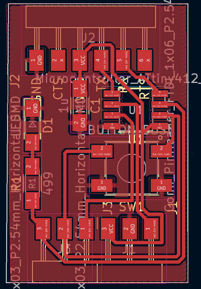
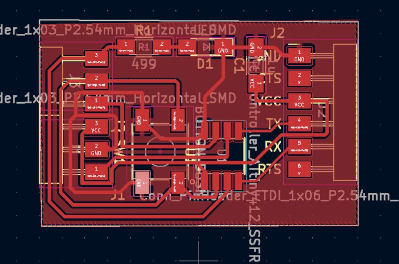
Physical setup of the board
The setup is an extended version of the one used in the Output devices week, see the link. The layoyt of the board is shown below.
Because the location of the temperature sensor is often at the measurement point of interest instead of the heat producing microcontroller board, I did not produce a circuit board for it but used wires instead.
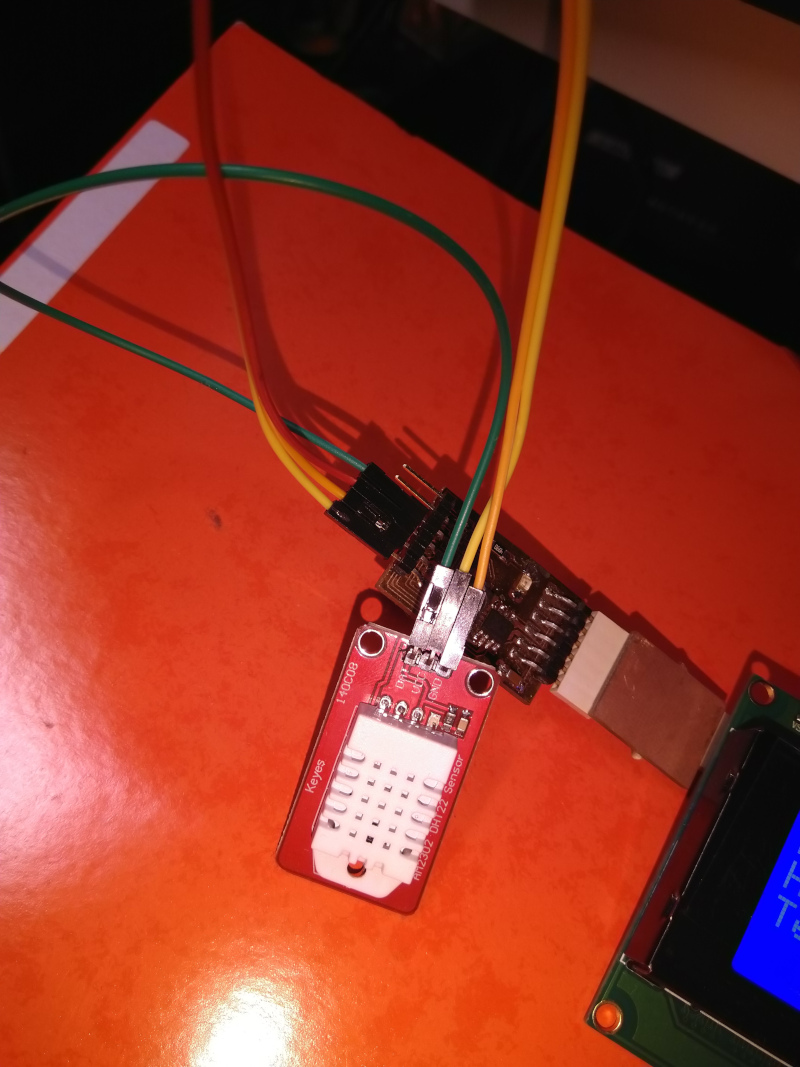
Connecting the sensor
The final project will receive proper wiring harness for connecting the parts together. Here we use prototype quality wiring.
The 140C08 sensor module requires three wires to connect it to the host system. DAT wire was connected to PIN 4. This was the next pin above the wires going to UPDI programmer.
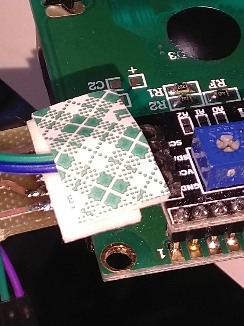
The +5V and Ground wires are taken from the LCD module connector. The wires are kept in place by friction, but also taped to the position. Note that this was a prototype version of the wiring. There is a proper harness installed in the system now, see details in the end of this document.
The layout of the microcontroller is shown below. The data is read from the third pad (up-down direction) from the left. GND and +5V are read from the first and third pad (up-down direction) from connector on the right, on the other side of the adapter connected to the module.
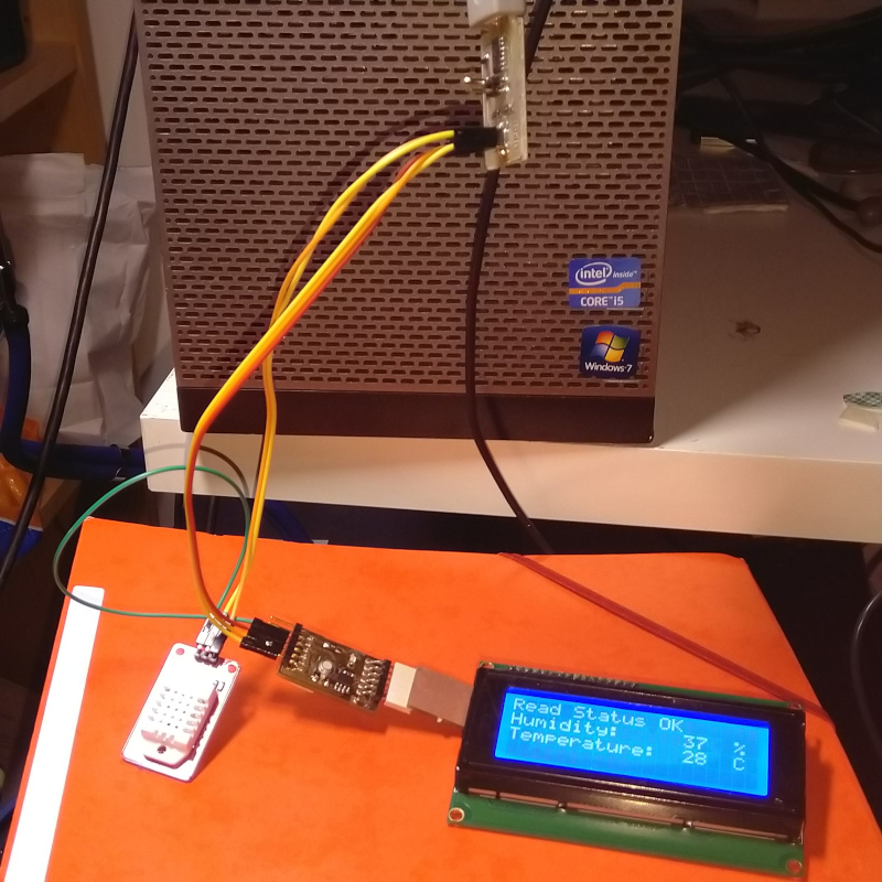
The results
The microcontroller board shows quikly the initiation screen and then reads the temperature and humidity data from the Kryes 140C08 module (DCT22 sensor) and displays it on the LCD module.
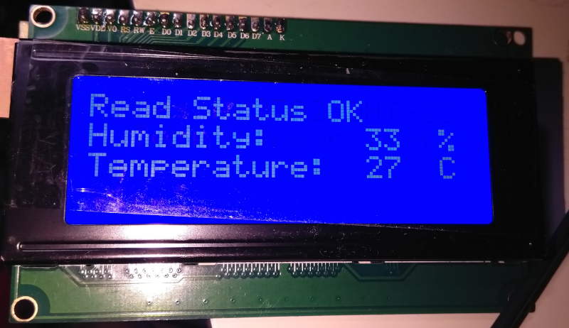
Here is a short video showing the display in the setup:
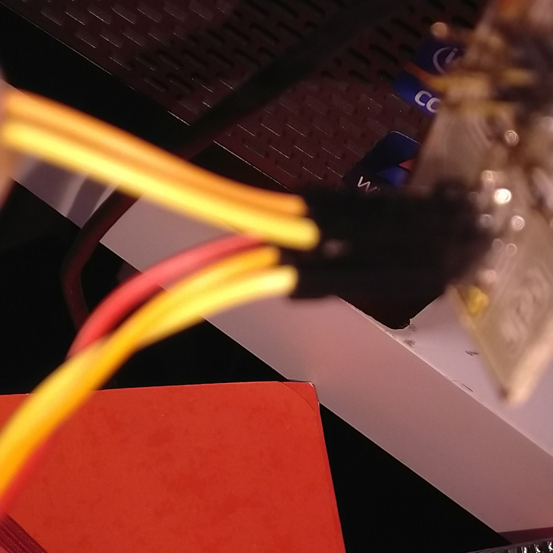
Additional fix - bettwe wiring harness
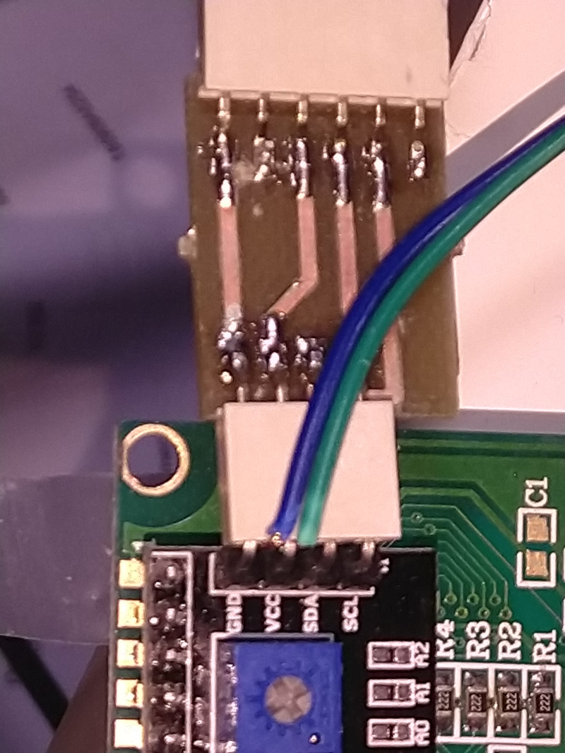
I noticed, that all the wires should be either soldered or connected by connectors. Therefore I took the power to the sensor directly from free connectors from UPDI programmeer. The pinout of UPDI is strange in that sense, that the second set of three connectors has a different order of signals. GND is the middle pin on both the sides, but GND and +5 V change positions.
Please see the images of the fixed wiring harness below. The green wire going to the sensor is the data pin to the microcontroller. Orange wire is GND and Yellow wire +5 V. See the three images below for details, that the wiring harness is properly made.