10. Molding and casting
Group assignment:
-
Review the safety data sheets for each of your molding and casting materials
-
Make and compare test casts with each of them
-
Here is the link to the current version of the group documentation for this week.
Individual assignment:
- Design a 3D mould around the stock and tooling that you’ll be using, mill it (rough cut + (at least) three-axis finish cut), and use it to cast parts.
Learning outcomes
-
Design appropriate objects within the limitations of 3 axis machining
-
Demonstrate workflows used in mould design, construction and casting
Have you answered these questions?
-
Linked to the group assignment page and reflected on your individual page what you have learned
-
Reviewed the safety data sheets for each of your molding and casting materials, then made and compared test casts with each of them
-
Documented how you designed your 3D mould and created your rough and finish toolpaths for machining, including machine settings
-
Shown how you made your mould and cast the parts
-
Described problems and how you fixed them
-
Included your design files and ‘hero shot’ of the mould and the final object
Individual task
Design a 3D mould around the stock and tooling that you’ll be using, mill it (rough cut + (at least) three-axis finish cut), and use it to cast parts.
3D design
I read the previous year student, Motahareh Peyvasteh recommendation not to get stuck in 3D design. I decide to make a simple design, I decided to make a nice cube.
Design in Fusion 360
I made a first try. It failed because I had used features smaller than the drill size. I wasn’t happy for the design so I started from beginning.
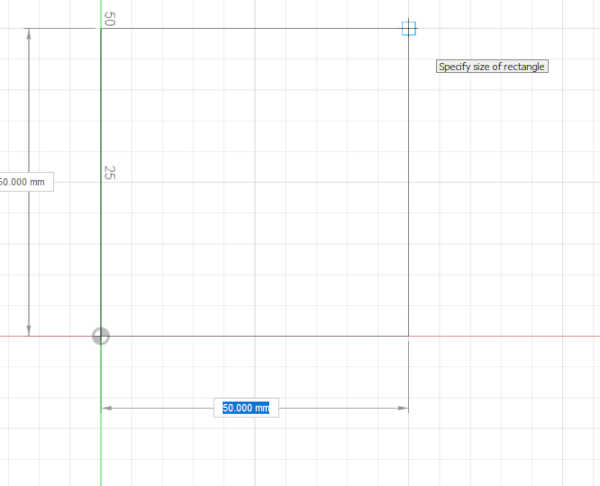
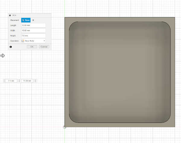
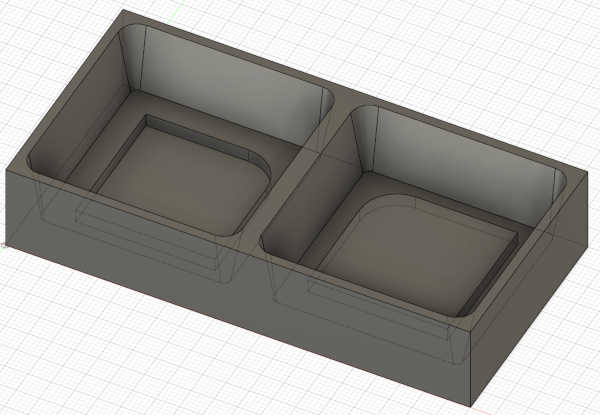
I created Body -> Box.
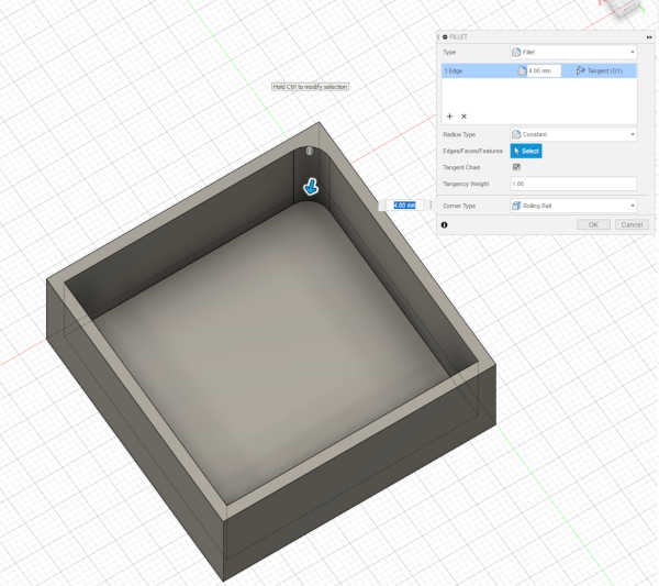
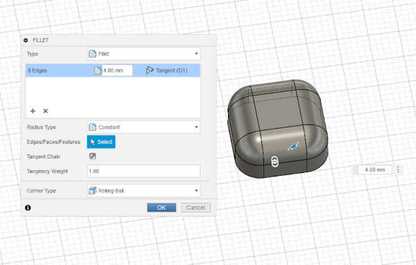
I rounded the corners with fillet (shortkey F). Radius 4 mm.
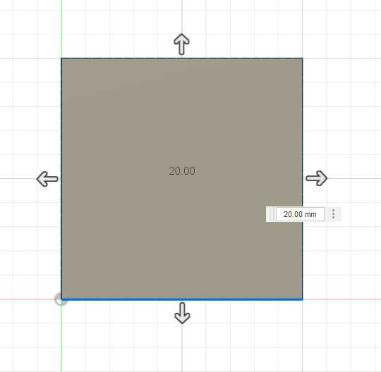
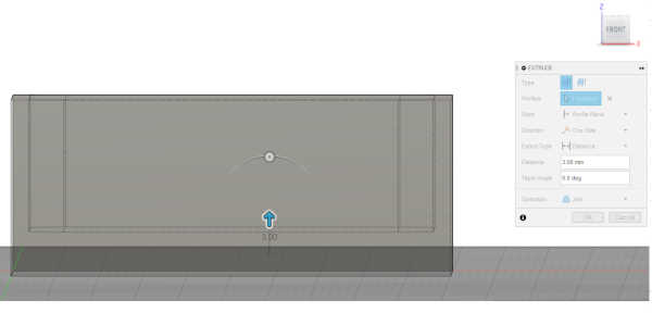
I extruded (shortkey E) the floor for 3.0 mm in order to gain space for tap features.
I created a box (Body -> Box).
I filletted the box (shortkey F) with 4.0 mm radius.
I drafted Modify -> draft, upper face as pull direction for the interior walls. I used 10.0 degree angle.
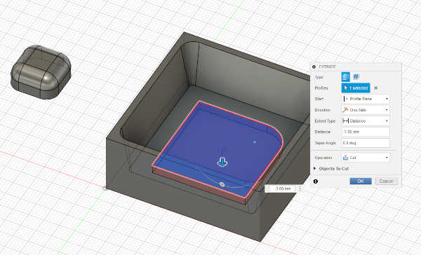
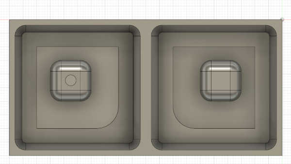
I created a sketch (Create -> Create Sketch) to the floor of the box. I drew a square and filleted one corner of the square, 8 degrees. I extruded the feature by -3.00 mm
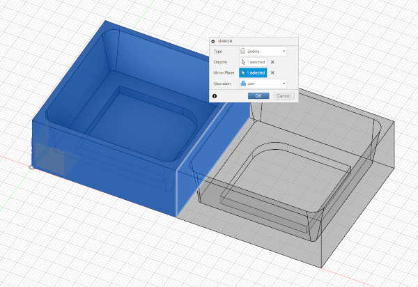
I mirrored (Create -> Mirror )the object.
I moved the object (shortkey M) to the mold in XY-plane and copied it (shortkey M) for the another half of the mold.
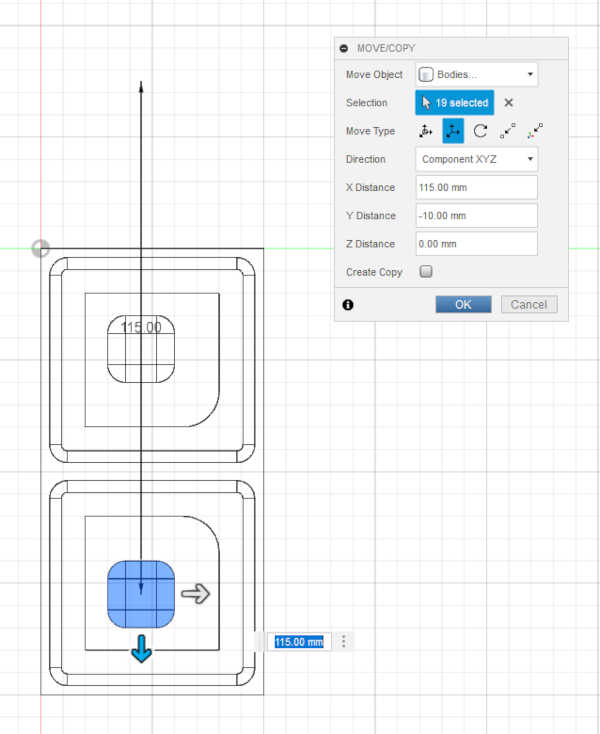
I moved the components to the right position in Z-direction.
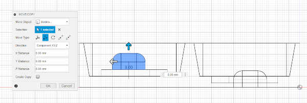
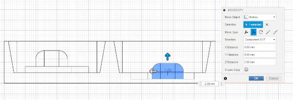
I created a sketch on top of the cube. I drew a circle of 2.00 mm radius.
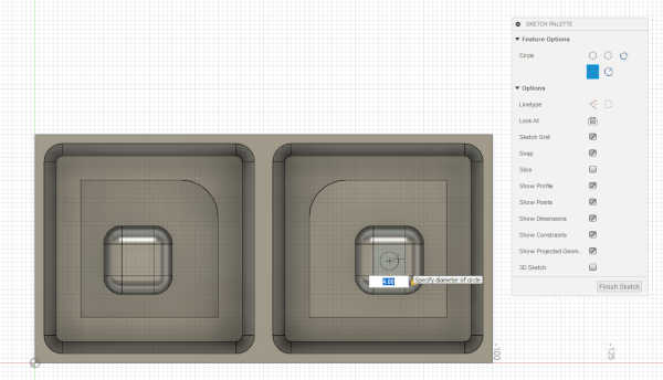
I extruded the circle with 4.5 mm, so that it reaches the edge of the mold box.
Then it was time to show the design to an instructor (Yrjö). There are still edges, that have problems with milling, so it was time for Modify -> Fillet. I used 4.0 mm as radius for the remaining corners of the mold sides. They should work with 3.16 mm tool.
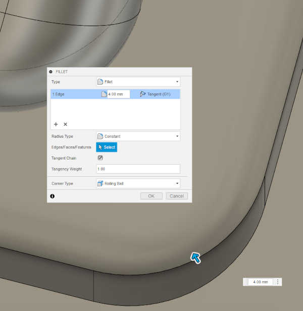
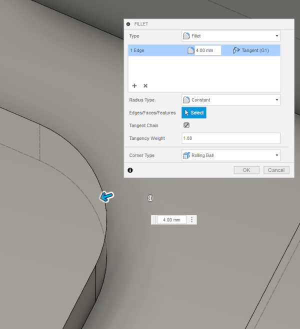
The corners were now rounded.
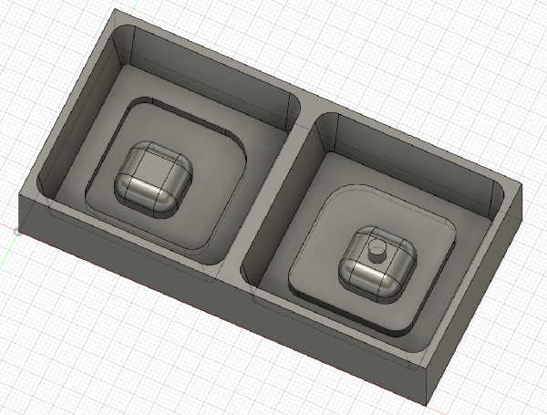
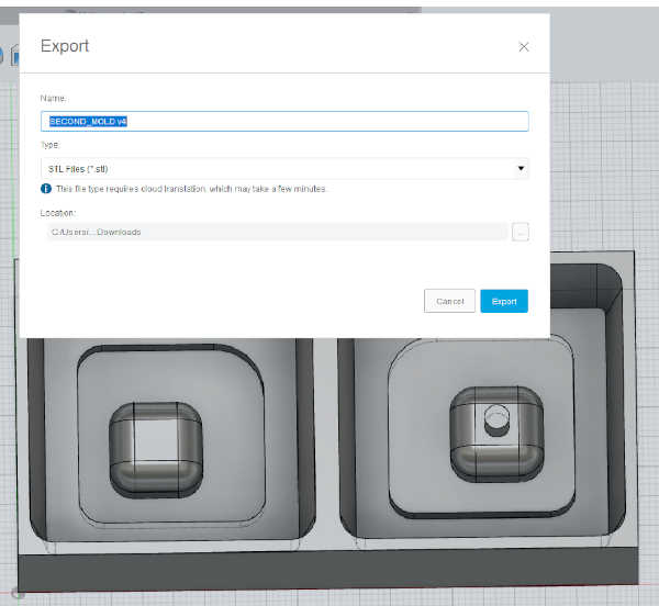
Then I exported the file as .stl file. The .stl file is available here. The creation of the .stl file concluded the desing phase of the mold done in the Fusion 360.
Milling the mold
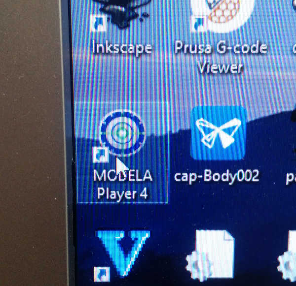
I opened the stl file in Modela player.
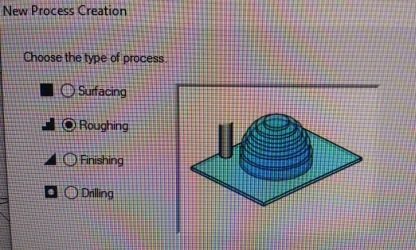
I chose the material to vax and created a new process.
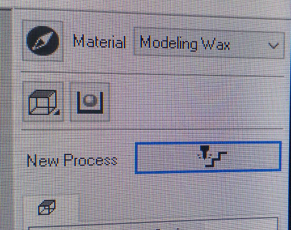
I chose roughing as the type of the process.
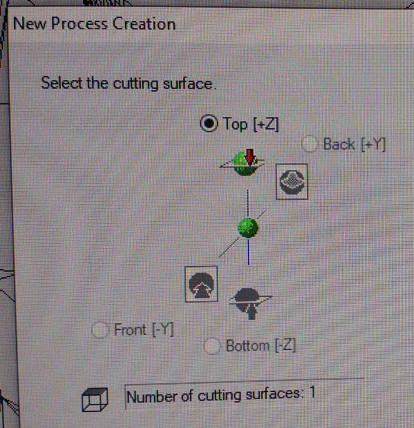
I chose the cutting surface and set the number of cutting surfaces to 1.
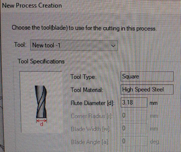
I chose 3.18 mm “square” steel blade as tool.
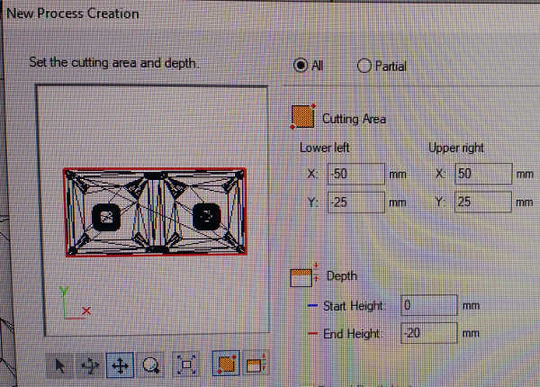
I selected the cutting region and paid attention to the dimensions of the mold (100 x 50 mm, centered origo, height 20 mm), The dimensions looked just fine.
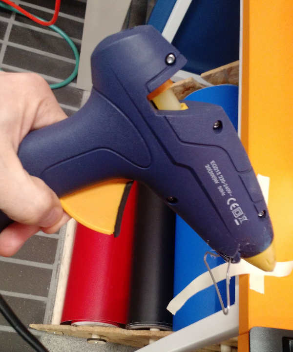
I taped the board and used hot glue to fasten the stock.
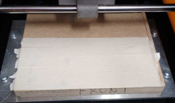
I chose the center point for the mill.
I chose the type of the toolpath (X+Y) for roughing.
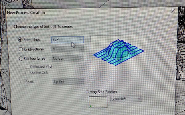
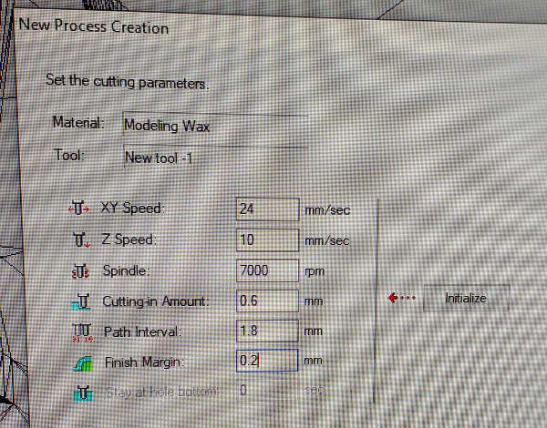
I chose the milling parameters. They are mostly based on last year’s Oulu student, Mona Peyasteh, values. I left 0.2 mm for finishing and probably made the milling grid too large. At least that’s what I was thinking when waiting the mill to finish. Perhaps I should have used a bit larger path interval and higher speeds? However, I wanted to play safe here in order to avoid mistakes.
I set the process name and used the default cutting position setup with origo in the middle of the cut as it was in the design.
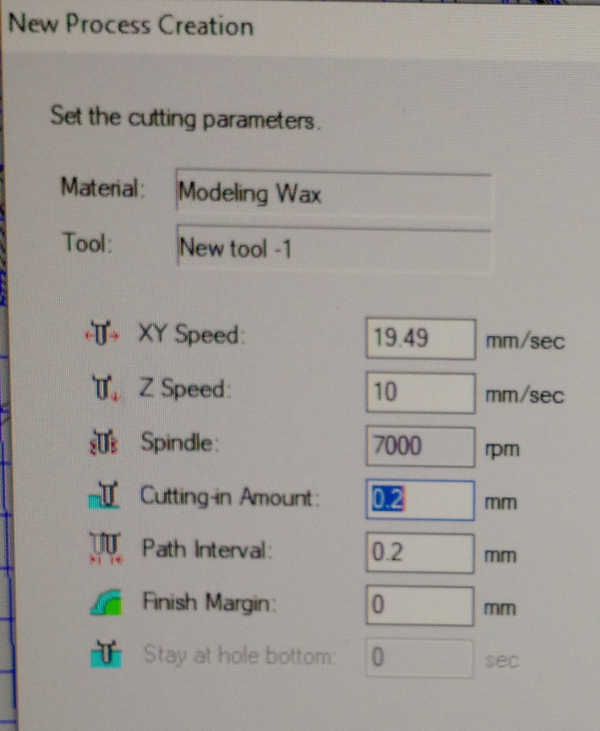
Then I started setting up the finishing process. For that I used contour lines (with Up Cut. I also used smaller cutting amount. This ended up being quite slow process as well.
The rouging prn file and finishing prn file were saved in the process.
I turned on the SRM-20 roland milling machine by pressing the power switch located on the top of the machine.
Then I opened VPanel for SRM-20 by clicking the icon on the Desktop.
Next I installed the milling bit by using the hexagonal tool and set up the XY plane origo and the Z direction to the point I marked to the stock earlier. The process was described in detail in the circuit board milling week.
The origo was placed over the good origo location in the wax stock.
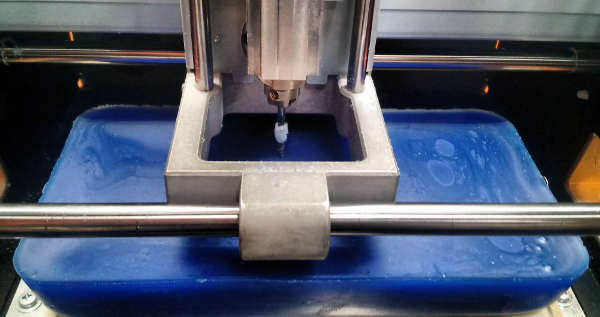
Then I pressed Cut to start the cutting process.
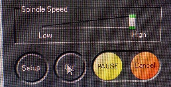
I loaded the prn file for the process.
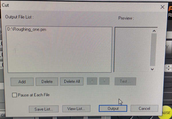
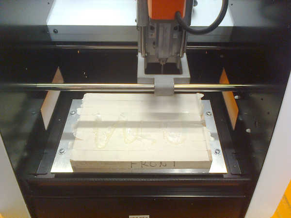
Pressing “Output” started the milling process. .
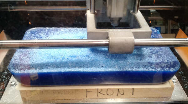
 Here is a phase, where I paused the mill to see what is going on.
After the rouging process was finished, I started the finishing mill. Because of closing time I had to stop the process, but I just restarted the process the next day. The coordinates were stored.
For finishing process I pressed again Cut, chose the finishing output file and started the cutting process by pressing Output.
The first run, including the roughing process, before interrupting the milling because of the closing time took 2 hours 10 minutes. The exact time for finishing the milling was unfortunately not stored properly for later documentation.
In the next day, when I restarted the milling I decided to mill the whole finishing run again, because I was not sure if interrupting the process had negative effects in the mold. The first half of the mold was already finished. That is why it is difficult to say the time the milling would have taken, if it was completed at one run. My time estimate for completing the milling process is about three hours.
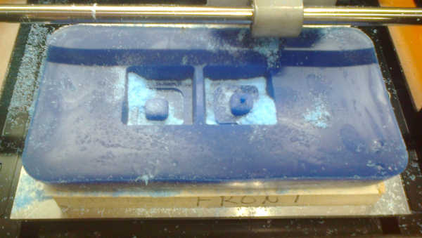
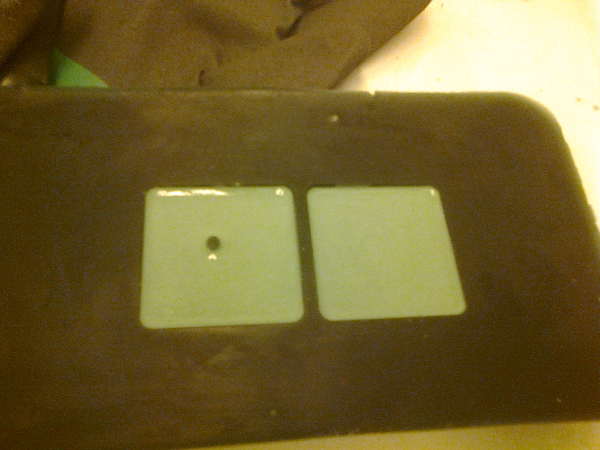
This was the result of milling.
Making the silicon mold
The next phase was to make the silicon mold for making the actual object.
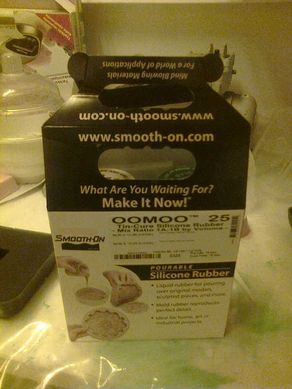
I chose OOMOO 25 as the material for the mold.
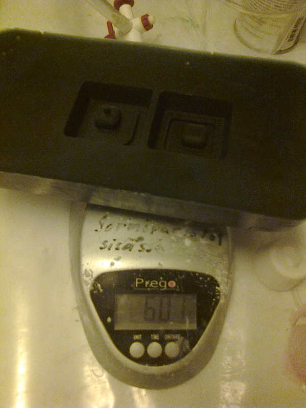
I weighted the mold empty.
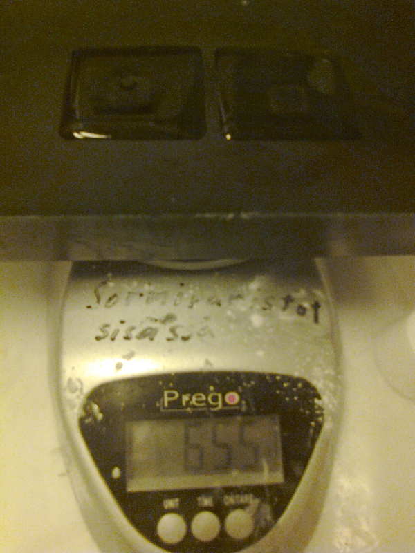
Then I weighted the mold filled with water.
I calculated the weight of water. Then I calculated the required amount of oomoo25 with the formula 100A:130B and put on some protective gear. See groupwork documentation for more info about the safety.
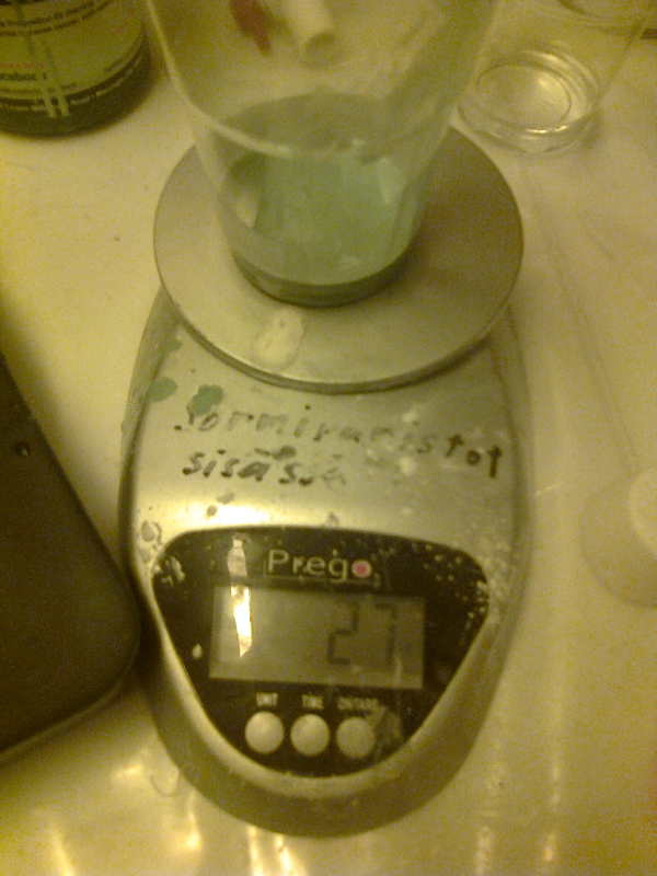
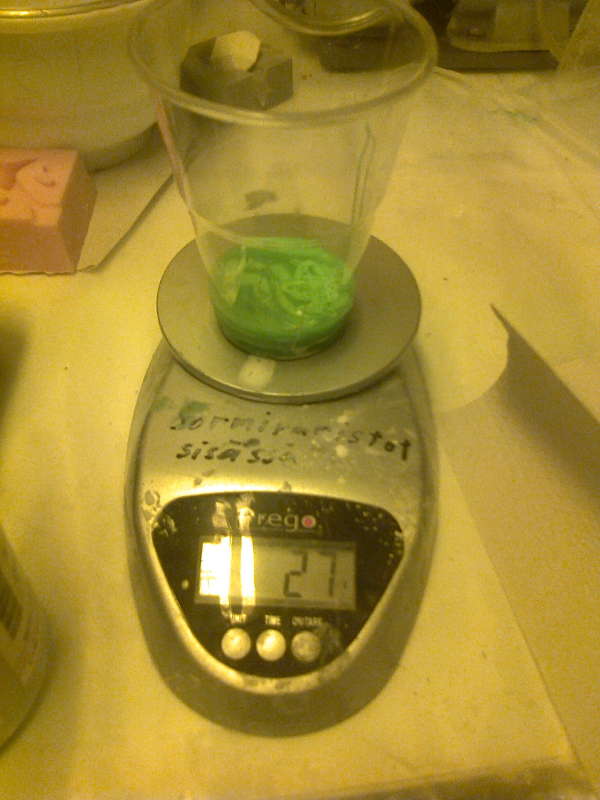
I added component A to a container.
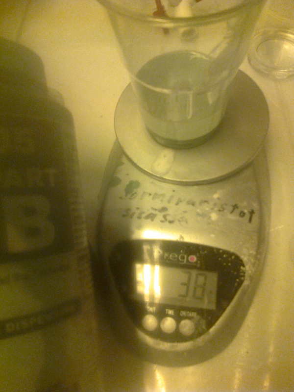
Then I zeroed the measurement and added component B.
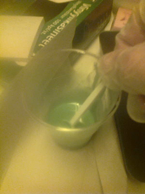
Then I mixed the components.
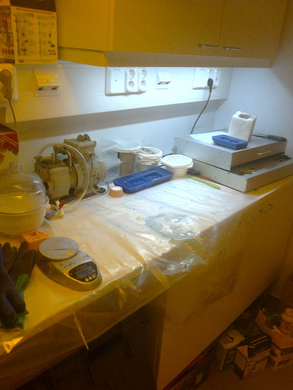
I used the vacuum pump to remove extra air from the solution.
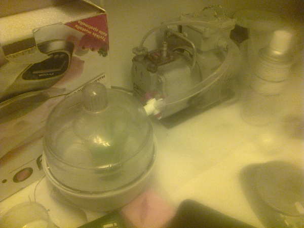
It was difficult to see through the glass, but I stopped pumping when the bubbles were clearly visible and removed the tap from the container.
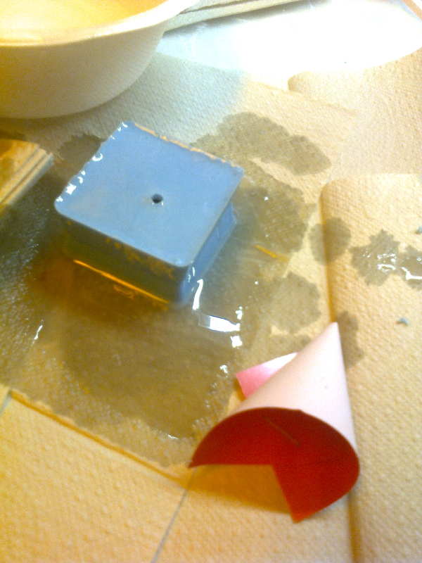
I dried the mold and added the mixture.
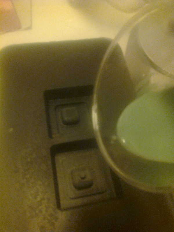
I filled until the mold was full.
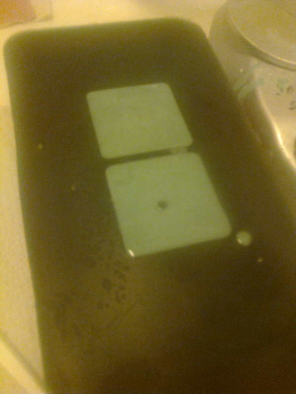
I left the mold to dry.
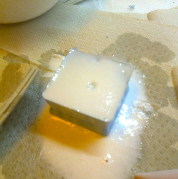
Making the silicon mold ver 2.0
The OOMOO 25 didn’t dry. It must have been faulty. So, the mixture was removed by paper and a new mixture was made. I used mask and protecting gloves while making the silicone mixture.
The mixture was measured by multiplying the mass ratio 100A:130B by roughly 2.5grams.
Unfortunately, stand-by mode (clock) activated in the middle of measurements when adding B, so the ratio wasn’t as accurate as I planned it to be.
This time the vacuum chamber was not used, because I heard at Wednesday’s lectures that it was not neccessary with OOMOO 25.
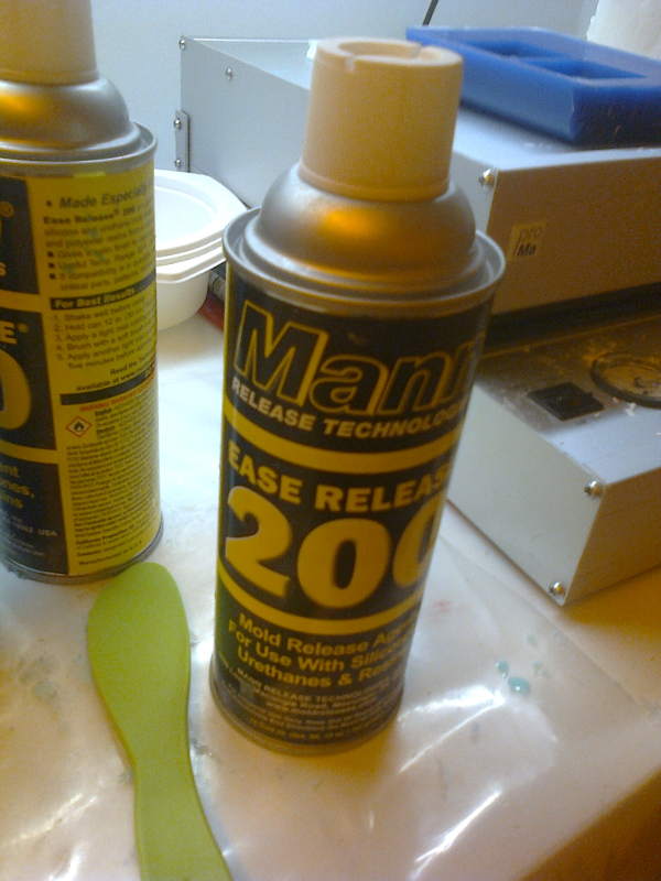
I sprayed the mold with a release agent, even if it was not neccessary.
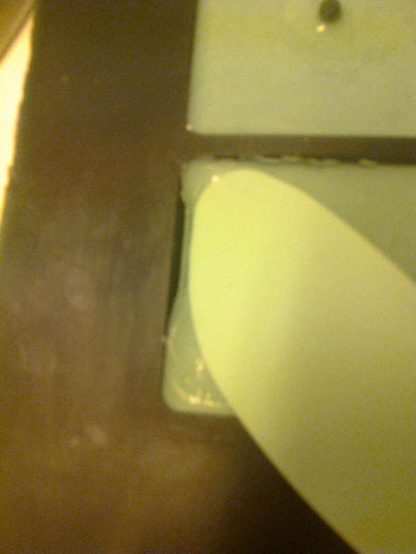
The mixture was then poured into the mold.
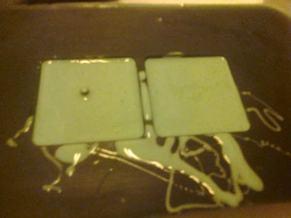
After a couple of hours (well over the curing time of 75 minutes) the molds were hardened.
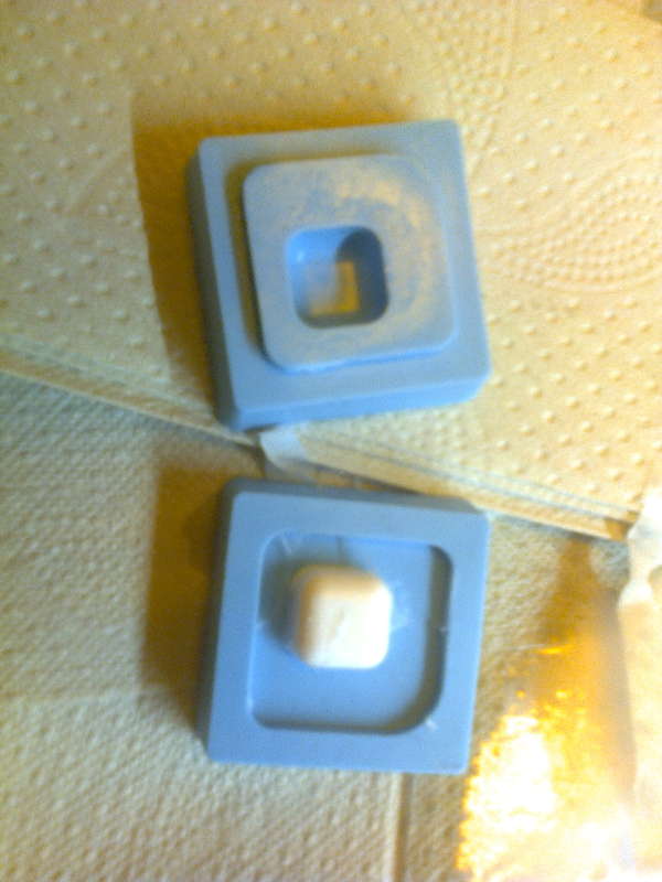
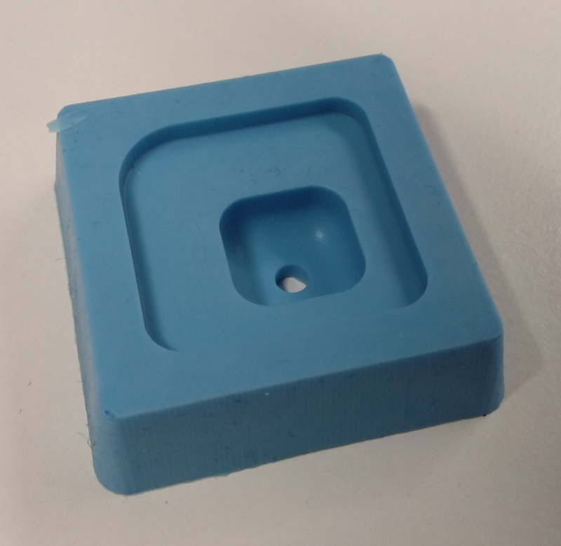
First I removed the overpoured part.
I bent the corners of the mold so that the silicon was detached from the vax.
The molds appear to fit to each other. The fit is tight, but I have no experiece to evaluate, if the fit is too tight. Too tight fit might bent the inner mold.
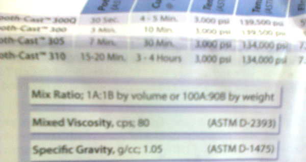
I chose to use SmoothCast 305 for casting the object on the silicone mold.
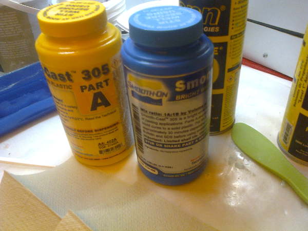
I read the instruction sheet for the material. 100A:90B, 7 min to pour, 30 minutes to cure were the main points.
The material is more harmful, so I made sure the ventilation was turned on.
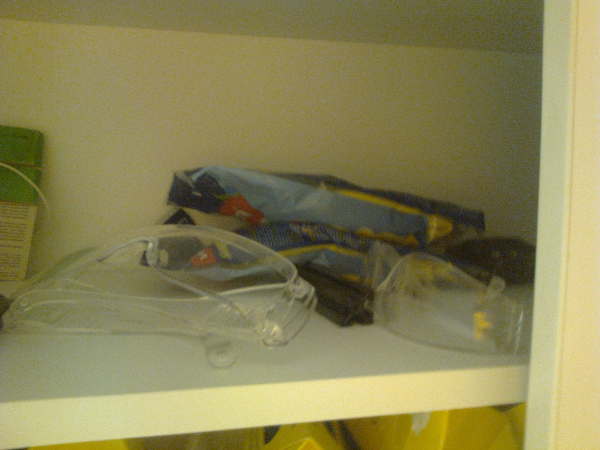
I also put on the labcoat and proper protective gloves for handling the material. I also wore mask for safety reasons.
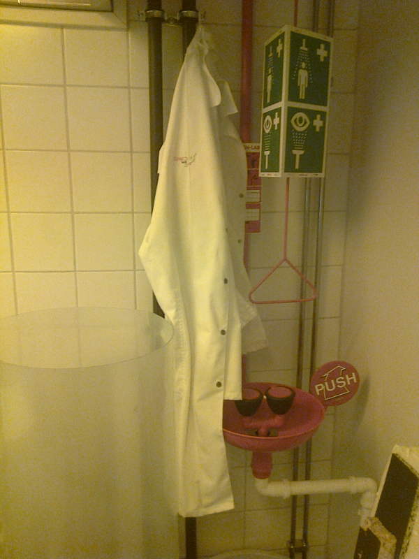
I cut the pouring hole open and constructed a cone for pulling the material. There was no injection syringe, I would have preferred available, and we were also out of plastic spoons and cups. The results were quite messy. I ended up pushing the excess air out from the mold by bending the mold a bit.
After curing time, the messy work realised. There was a lot of extra material to remove.
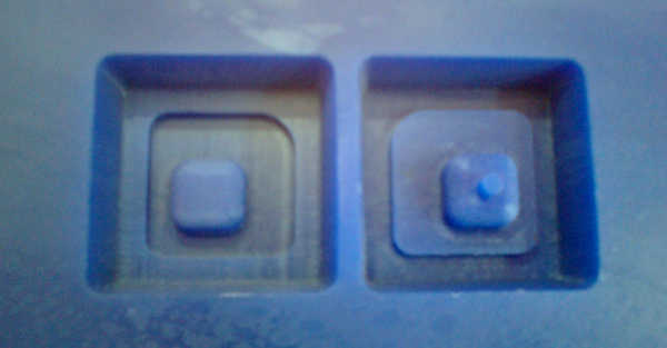
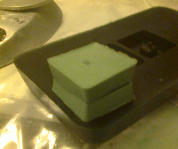
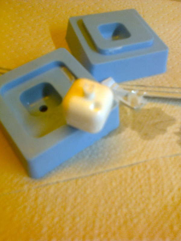
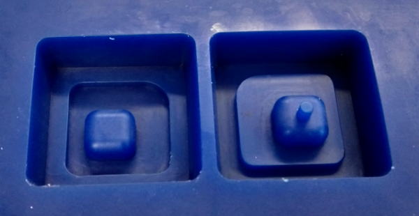
The mold was opened and the results looked promising.
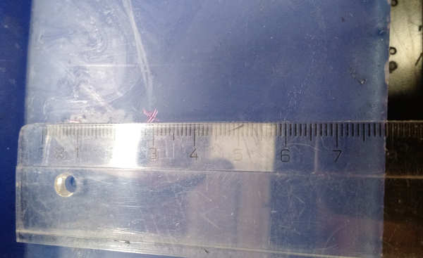
There was a minor bubble left inside the mold on the upper side.
I did some basic tidying on the desk, put the safety equipment where I found them and turned the ventilation off.
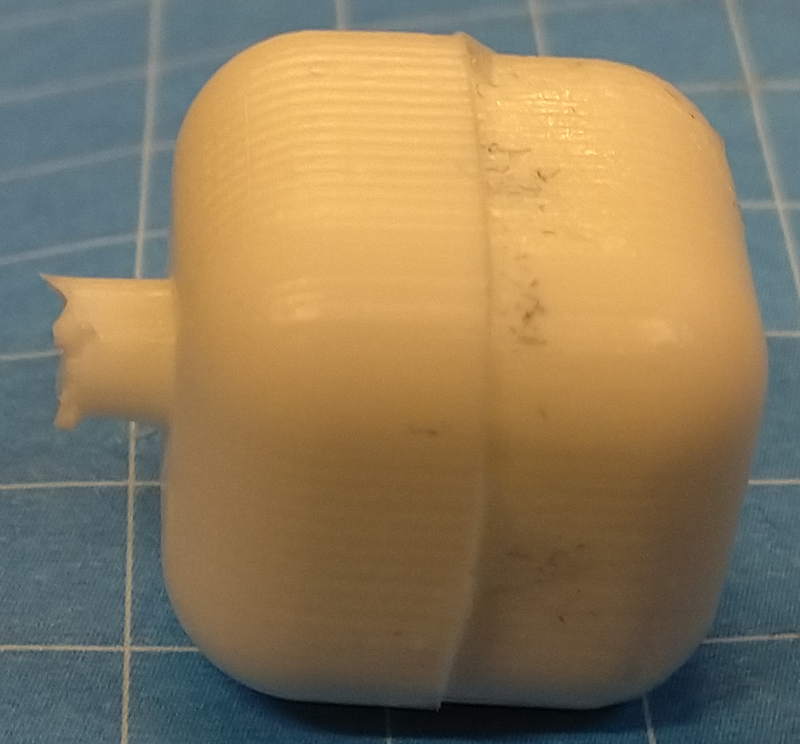
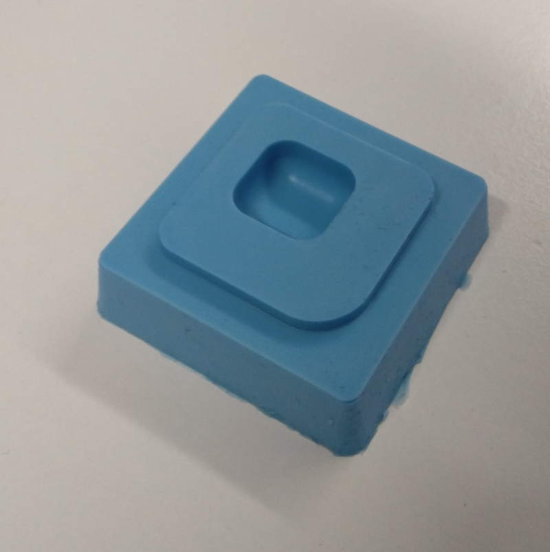
The results
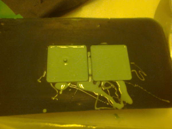
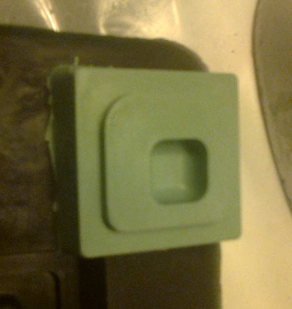
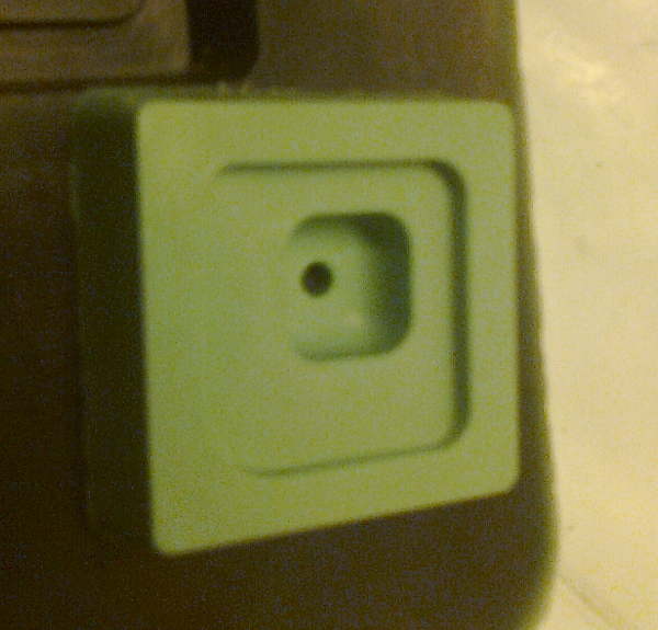
Here are better pictures of the item and the molds
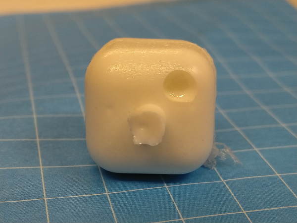
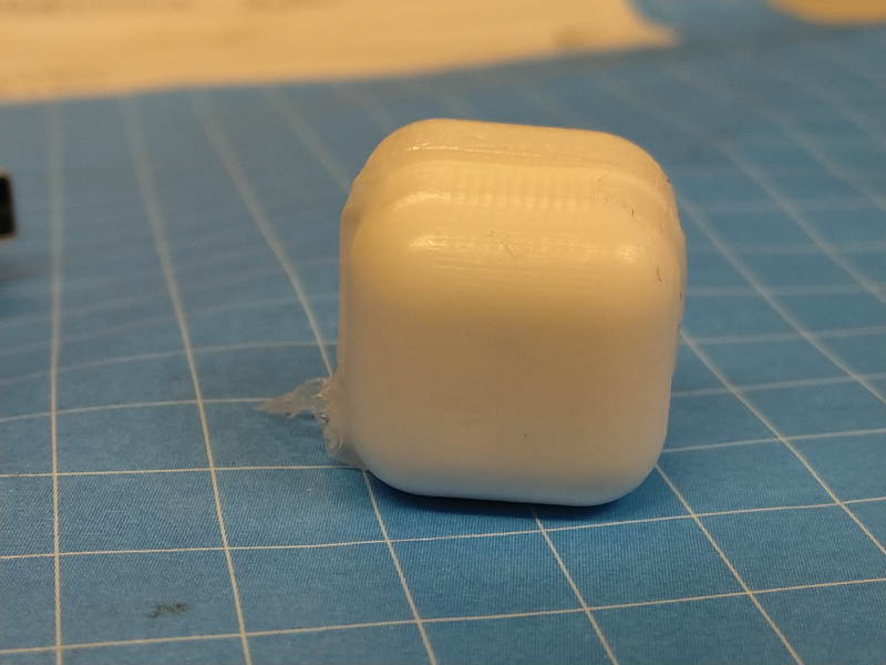
The milling artefacts are clearly visible and it is possible that the lower part of the mold was bent or there was a problem because of a pause in the milling of the mold. The parts didn’t fit properly. In the design file, the upper and lower parts were identical in size. I strongly suspect that running the finishing process twice to the first part of the mold resulted additional loss of material in that half contributing to the mismatch, even if the run path should have been identical.
The molds survived the use quite well.
What I will do differently next time
Next time I avoid pausing the mill and use smaller bit for finishing phase. I also will find an injection syringe for filling the mold and add holes for air. I am happy with the two-part mold desing. The parts did fit and the desing hold the right orientation.