15. Interface and application programming
individual assignment: write an application that interfaces a user with an input and/or output device that you made.
group assignment: compare as many tool options as possible
Individual assignment
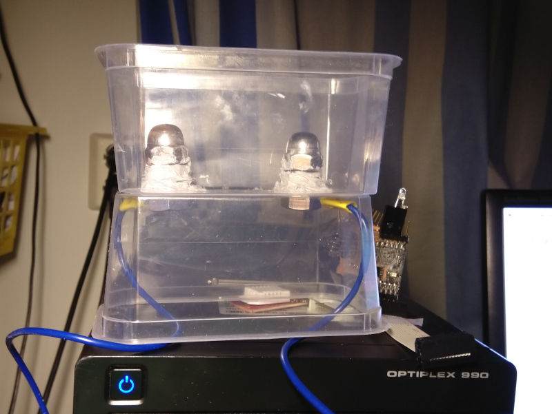
I decided to make an user interface for my final project. The mechanical part is not fully designed, but I have already made a prototype of an electrolysis pool. The UI should turn the relay on /off, read temperature data and display the status of the board. For doing that, the software for the microcontroller should be written first.
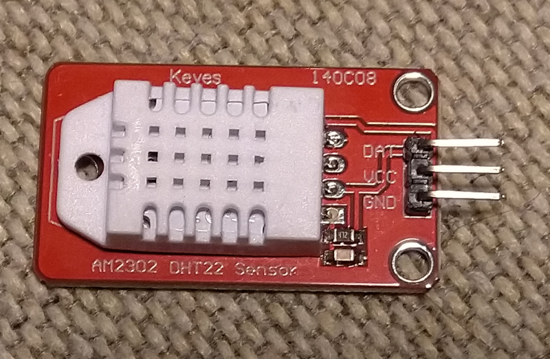
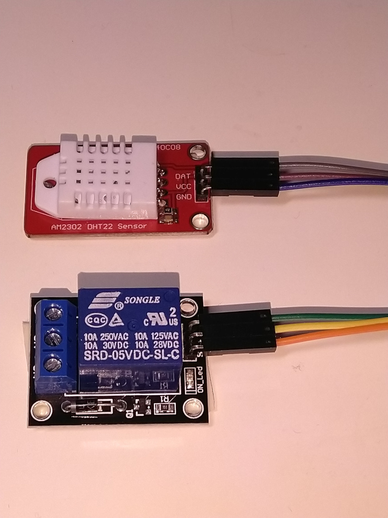
The input data read comes from DHT22 temperature / humidity sensor on Keyes AM2302 DHT-22 Module. The same sensor was used in the Input devices week .
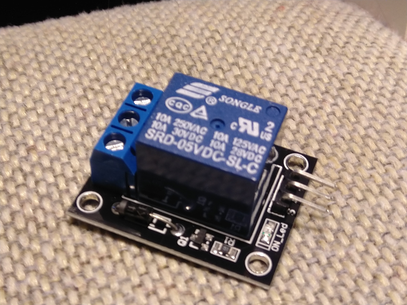
The final project requires control of electrolysis current. This is done by on/off relay. A relay module, Keyes SR1y is used for this purpose.
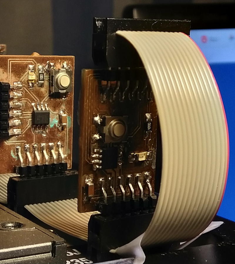
The microcontroller card used is based on ATtiny 412 microcontroller. This microcard was designed on the Electronics Design week. It was used on the Networking and Communications week as card one in the bus.
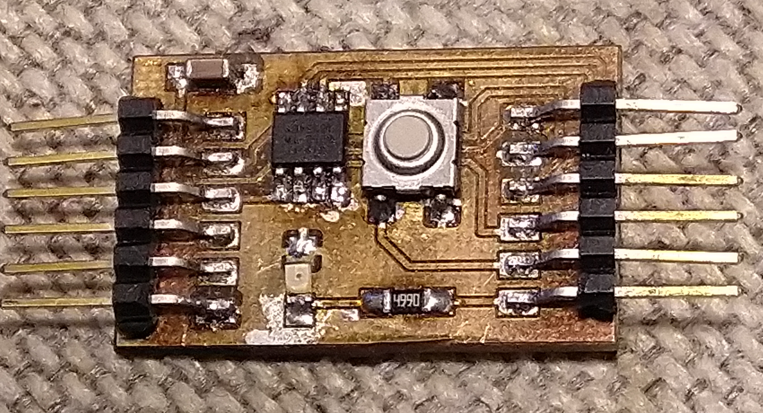
The same setup used for connecting the card and programming it is still used for development. The card is stil connected on a bus, while it can perfectly well work without it.
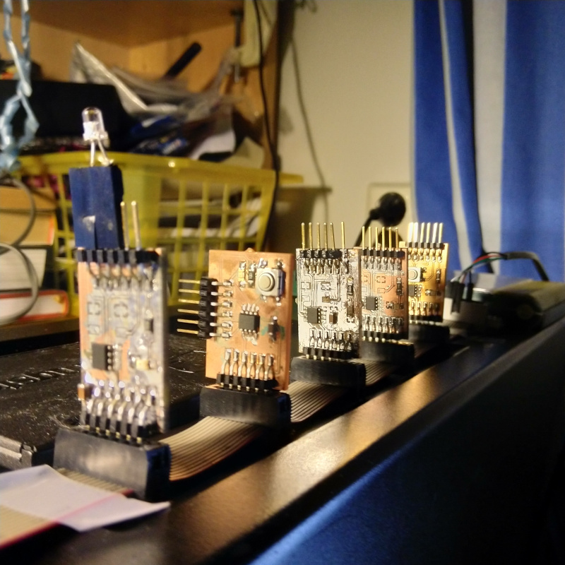
The bus is connected to PL2303HX USB to TTL RS232 COM UART Module Serial Cable module USB to UART cable.
The programming is done with a D11C14A based UPDI programmer we used on the Electronics Production week.
Building the Setup
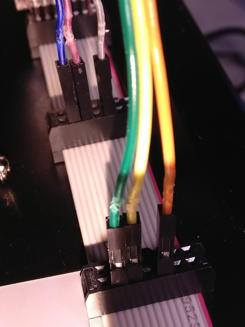
The bus used on Networking and Communications week has 14 pins. Only 6 pins of the first pin line of the bus is currently used for serial bus and power distribution for the boards. I decided to use the other pins for signaling and power for DHT-22 and SR1y.
Wires for connecting SR1y and DHT-22 to the bus were installed.
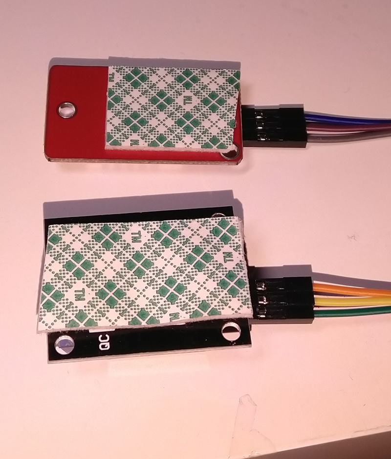
The back sides of the circuit boards were insulated.
The cabling was connected to the bus.
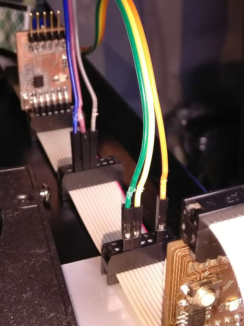
Note that because power and ground are available on both sides of the board, only one slot is required for connecting both the external components.
Microcontroller code
The prototype code in the microcontroller side inputs one letter commands from the serial host and returns the data on the serial bus.
The microcontroller outputs used are * txPin (2) transmit signal to the bridge
-
rxPin (3) receive signal from bridge
-
DHTPIN (4) for reading DHT22 sensor values.
-
relayPin (0) Connected to the third pin, just next to power in. Turns on/off the external Keyes_SR1y relay module.
The current command set is:
- 1: Return node is alive message. Helps in debugging.
- a: Turn off led
- A: Turn On led
- h: return humidity value
- t: return temperature value
- r: turn relay off
- R: turn relay off
My current program code for controlling the board is shown below. The code is still untested / under progress.
/*
Program for handling the serial programming
*/

#include <SoftwareSerial.h>
#include <Wire.h>
#include <DHTStable.h>

#define txPin 2 // PA1(MISO) transmit signal to the bridge

#define rxPin 3 // PA2(SCK) receives signal from bridge

#define keybuttonPin 4 // Connected to second pad on programmer connector
#define relayPin 0 // Connected to the third pin, just next to power

#define DHTPIN 4  // DHT sensor pin
#define DHTTYPE DHT22   // DHT 22  (AM2302)

#define RELAY_ON 1      // Define relay on pin state
#define RELAY_OFF 0     // Define relay off pin state

SoftwareSerial mySerial(rxPin, txPin); // RX, TX

const char node = '1'; // network address

const int ledPin = 1; // the number of the LED pin (default 1)

int incomingByte;

int state = LOW;

int humidity =0;
int temperature =0;
int chk;
// Initialize the humidity and temperature variables

DHTStable DHT; // initialize the DHT library


void setup() {

  // Turn relay off and set pinMode Output
  digitalWrite(relayPin, RELAY_OFF);      // initialise the relay to off
  pinMode(relayPin, OUTPUT);
  delay(1000);

  mySerial.begin(9600);

  pinMode(ledPin, OUTPUT);

  pinMode(txPin, INPUT);

  digitalWrite(ledPin,LOW);


}

void loop() {

  chk = DHT.read22(DHTPIN); // Read DHT22 data.

  // Read temperature
  temperature  = DHT.getTemperature();

  /*// Read humidity
  humidity = DHT.getHumidity();
  */
  if (mySerial.available() > 0) {
    incomingByte = mySerial.read();


/* Command reference for UI_Node1
 *  1: Return node is alive message.
 *  a: Turn off led
 *  A: Turn On led
 *  h: return humidity value
 *  t: return temperature value
 *  r: turn relay off
 * R: turn relay off
*/

switch(incomingByte)
{/*
    case '1':
      pinMode(txPin, OUTPUT); // open line to write

      mySerial.print("Node ");
      mySerial.print(node);
      mySerial.println(" is alive.");

      pinMode(txPin, INPUT);
      break;

     */
    case 'a':
      digitalWrite(ledPin,LOW);
    break;

    case 'A':
    digitalWrite(ledPin,HIGH);
    break;

    case 'R':
    digitalWrite(relayPin, RELAY_ON);
    delay(1000);
    break;

    case 'r':
    digitalWrite(relayPin, RELAY_OFF);
    delay(1000);
    break;

    case 't':
    mySerial.println(temperature);
    delay(1000);
    break;

    case 'h':
    mySerial.println(humidity);
    delay(1000);
    break;

    // status query

    case 's':
  switch (chk)
    {
    case DHTLIB_OK:
        mySerial.println("Read Status OK");
        break;
    case DHTLIB_ERROR_CHECKSUM:
        mySerial.println("Checksum error");
        break;
    case DHTLIB_ERROR_TIMEOUT:
        mySerial.println("Time out error");
        break;
    default:
        mySerial.println("Unknown error");
        break;

    }
    break;

    default:
     break;
      }
   }


}
Memory issues
The code above did not fit in the memory of the ATtiny412. Th obvious alternative for decreasing the code size was just to use separate boards for control and sensor. However, the serial library SoftwareSerial is known to take quite a lot of memory. So, I decided to look for alternatives. After a lot of research, I ended up in a solution to use the default hardware serial library. The additional features SoftwareSerial library provides were actually not required at this phase of the project.
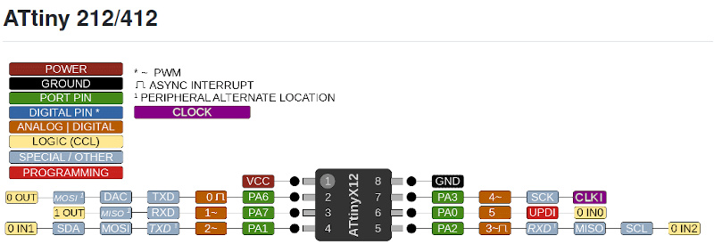
The hardware serial had less flexibility in selecting the pins for TX and RX than SoftwareSerial has. See the diagram below. RXD TXD pair and RXD1 TXD1 pair are the options available for hardware serial. The default pinscould not be used, but the alternate pins were free. The alternate pins are selected by Serial.swap(1);-command. Leaving the extra libraries out solved the memory problem.
Revised program for the microcontroller
The result of debugging was the following code:
/*
Program for handling the serial programming
This version uses standard serial library
*/

#include <DHTStable.h>

#define relayPin 0 // Connected to the third pin, just next to power and to button

#define DHTPIN 4  // DHT sensor pin
#define DHTTYPE DHT22   // DHT 22  (AM2302)

#define RELAY_ON 1      // Define relay on pin state
#define RELAY_OFF 0     // Define relay off pin state


const char node = '1'; // network address

const int ledPin = 1; // the number of the LED pin (default 1)

int incomingByte;

int state = LOW;

// Initialize the humidity and temperature variables
DHTStable DHT; // initialize the DHT library
int temperature;
int humidity;
int intchk;

unsigned long lastTime = 0;

void setup() {

  // Turn relay off and set pinMode Output
  digitalWrite(relayPin, RELAY_OFF);      // initialise the relay to off
  pinMode(relayPin, OUTPUT);
  Serial.swap(1);
  Serial.begin(9600);

  pinMode(ledPin, OUTPUT);

  pinMode(DHTPIN, INPUT);

  digitalWrite(ledPin,LOW);
  // Read initial humn and temp values
   // temp = DHT.getTemperature();
   // hum = DHT.getHumidity();

}

void loop() {
  //delay(2000);
  //intchk = DHT.read22(DHTPIN);
   //temperature  = DHT.getTemperature();
  //humidity = DHT.getHumidity();
 if (Serial.available() > 0) {
    incomingByte = Serial.read();


/* Command reference for UI_Node1
 *  1: Return node is alive message.
 *  a: Turn off led
 *  A: Turn On led
 *  h: return humidity value
 *  t: return temperature value
 *  r: turn relay off
 * R: turn relay off
*/

switch(incomingByte)
{

#ifdef DEBUG
    case '1':
      Serial.print("Node ");
      Serial.flush();
      Serial.print(node);
      Serial.flush();
      Serial.println(" is alive.");
      Serial.flush();
      break;
#endif

    case 'a':
      digitalWrite(ledPin,LOW);
#ifdef DEBUG
      Serial.println("Led off");
      Serial.flush();
#endif
          break;

    case 'A':
    digitalWrite(ledPin,HIGH);

#ifdef DEBUG
   Serial.println("Led on");
    Serial.flush();
#endif
    break;

    case 'R':
    digitalWrite(relayPin, RELAY_ON);
#ifdef DEBUG
    Serial.println("Relay on");
    Serial.flush();
#endif
    break;

    case 'r':
    digitalWrite(relayPin, RELAY_OFF);
#ifdef DEBUG
    Serial.println("Relay off");
    Serial.flush();
#endif
    break;

    case 't':
    intchk = DHT.read22(DHTPIN);
    delay(3000);
    temperature  = DHT.getTemperature();
    Serial.print("Temperature: ");
    Serial.println(temperature);
    Serial.flush();
    break;

    case 'h':
    intchk = DHT.read22(DHTPIN);
    delay(3000);
    humidity  = DHT.getHumidity();
    Serial.print("Humidity: ");
    Serial.println(humidity);
    Serial.flush();
    break;

    // status query


 #ifdef DEBUG

    case 's':
  switch (intchk)
    {
    case DHTLIB_OK:
        Serial.println("Read Status OK");
        Serial.flush();
        break;
    case DHTLIB_ERROR_CHECKSUM:
        Serial.println("Checksum error");
        Serial.flush();
        break;
    case DHTLIB_ERROR_TIMEOUT:
        Serial.println("Time out error");
        Serial.flush();
        break;
    default:
        Serial.println("Unknown error");
        Serial.flush();
        break;

    }

    break;
 #endif
    default:
     break;
      }
   }

}
The code was tested. It turns the led on/off, turns the relay on/off and reads the temperature.
Simplifed hardware setup.
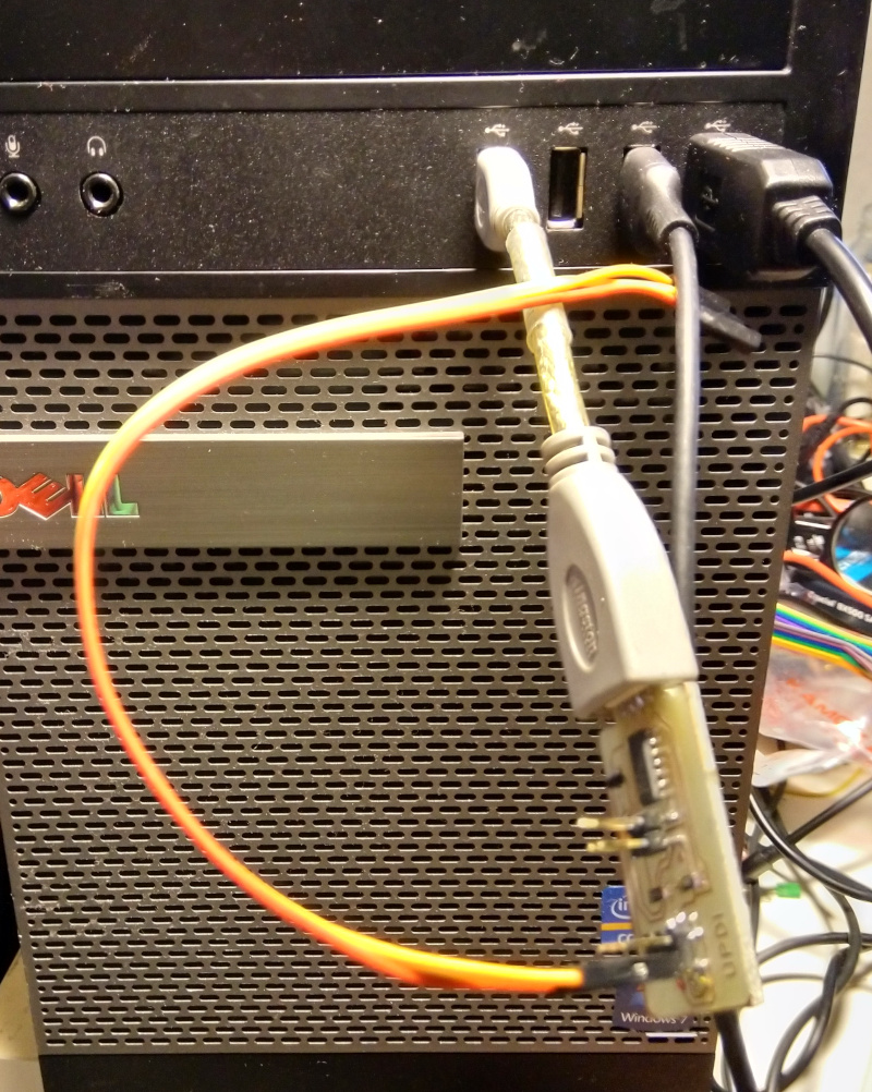
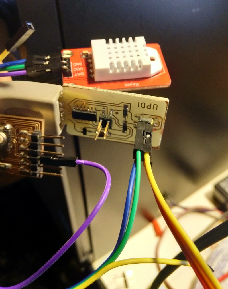
I also simplified the hardware setup from the networking week one. I powered the DHT-22 sensor directly from the UPDI programmer, so the sensor could be tested directly. Testing the SR1y relay module still required removal of the programmer connector and the board was then powered by the USB to UART cable. Note that the cabling is not of final project quality and depends on the laser cutted and 3D-printed parts not manufactured yet The focus of this week is in the user interface.
Pinout of the system
This is the pinout I used to test the system. This information is going to be useful in my final project.
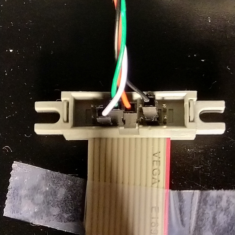
The cabling for the peripherals is shown below.
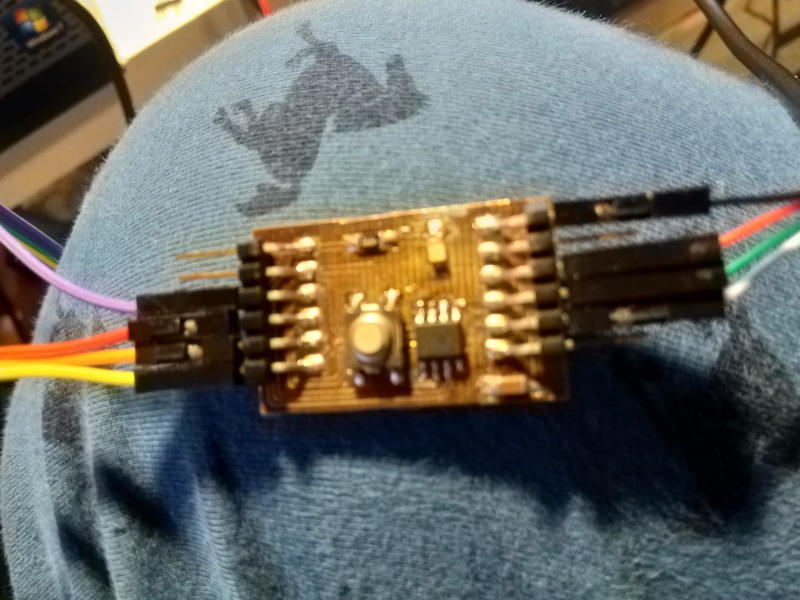
The cabling for the card is shown below.
The diagram for the pins is shown below:
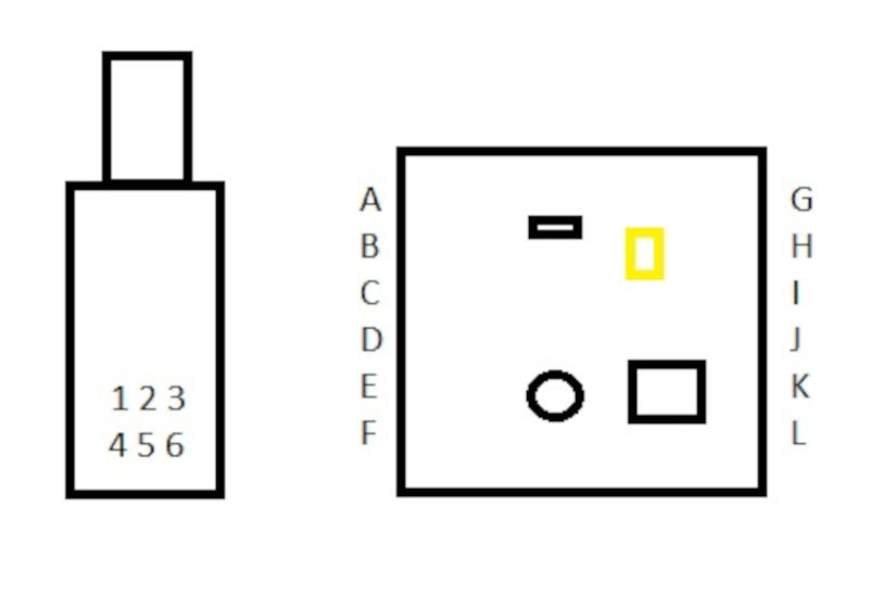
1 (Programmer UPDI data, not used here) 2 DHT22 ground. 3 DHT22 VCC. 4 Programmer provided VCC to the microcontroller (when programming). 5 Programmer provided GND to the microcontroller (when programming). 6 Programming UPDI data, connected when programming.
A Led signal out (Logical pin 1 in ATtiny412. B Signal to the SR1y relay module / button (Logical pin 0 in ATtiny 412) C Signal to DHT22 (Logical pin 4 in ATtiny 412) D VCC for the relay module / VCC from UPDI when programmer connected. E GND for the relay module / VCC from UPDI when programmer connected. F UPDI programmer connector (Logical pin 5 in ATtiny 412)
G USB to UART GND H N/C I USB to UART +5V J RXD1 of the microcontroller (Logical pin 3) K TXD1 of the microcontroller (Logical pin 2) L N/C
The user interface in Processing
Now when we have a test system which outputs data and takes commands as inputs, we can build an useful user interface for the system.
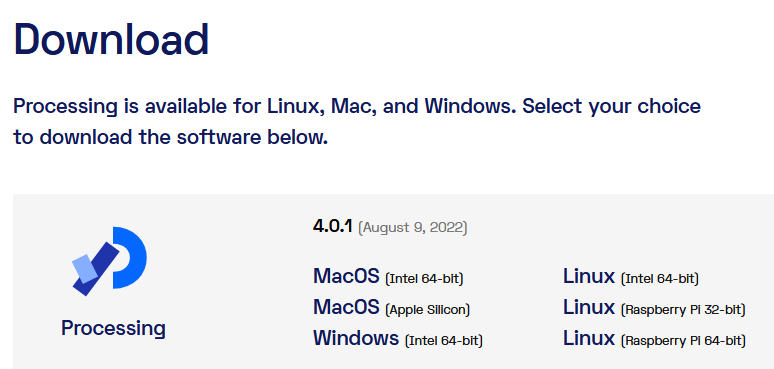
I decided to use Processing as the basis for the UI. I downloaded processing 4.0.1 from processing.org.
I extracted the file, browsed the directory until I found processing and clicked it. Processing opened.
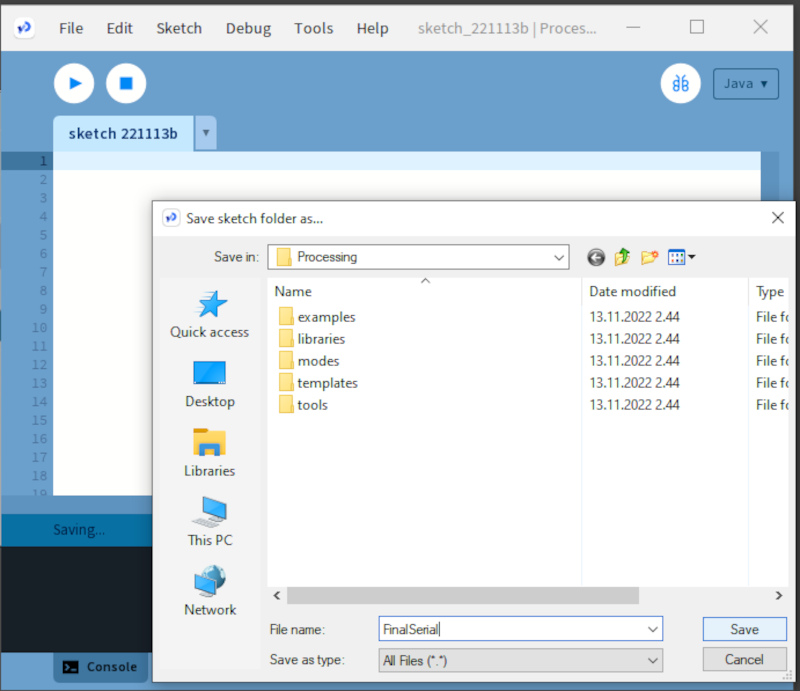
I saved the empty file as FinalSerial, because it is going to use serial bus and is part of my Final Project.
Then I went to Youtube and searched for “processing serial communication arduino” and started browsing examples. My goal is to find a working skeleton file for serial I/O interface for an Arduino board, preferably for the latest version of Processing.
I decided to start from [“Tutorial 06 for Arduino: Serial Communication and Processing”(https://www.youtube.com/watch?v=g0pSfyXOXj8).
After watching several Tutorials, I wrote the following program in processing.
// FinalSerial - UI for Final Project
// Antero Metso Fab Academy project 2022
/**
 * Simple Write.
 *
 * Check if the mouse is over a rectangle and writes the status to the serial port.
 * This example works with the Wiring / Arduino program that follows below.
 */


import processing.serial.*;
Serial myPort;  // Create object from Serial class

boolean ToggleLoop1= true; // Mouse toggle loop control

int val;        // Data received from the serial port

boolean ledStatus = false; // Led off on the beginning
boolean relayStatus = false; // Relay off in the beginning
boolean readingTemperature = false; // reading temperature;

String inBuffer ="***********************"; // this value seen if nothing read

PFont f;
int DHT22Counter = 0; // Variable for counter when to read the temperature and humidity values
void setup()
{
  size(200, 400);
  f = createFont("Arial",16,true); // Create Font
   textFont(f,11);                  // Specify font to be used
 String portName = Serial.list()[2];
  myPort = new Serial(this, portName, 9600);
}


// Draw

void draw() {
   while (myPort.available() != 0)
{
  inBuffer=myPort.readStringUntil('\n'); // clear serial buffer
 println(inBuffer);
};
  if (mouseOverRect() == true) {  // If mouse is over LED square,

   // Change fill color according to the led status;
  if(ledStatus)
    {
    fill(124,252,0);                    // change color to lawngreen
    } else
       fill(177,30,49);                    // change color to christmas red
   if (mousePressed && (mouseButton == LEFT)){
       ledStatus = !ledStatus;
      delay(200); // Avoid unniecessary toggling
       // Toggle led status if button pressed over square
               };
    } // Mouseoverrect true
    else {                        // If mouse is not over square,
  if(ledStatus)
    {
    fill(0,255,0);                    // change color to full red
    } else

       fill(255,0,0);                    // change color to fill green

  }; // Mouseoverrect else

  // Change led status according to the ledStatus Variable.
  if (ledStatus== false)
      {
        myPort.write("a\n");

      } else
        {
          myPort.write("A\n");

            inBuffer = myPort.readStringUntil('\n');

  }; // ledStatus false

  // Draw led square
  rect(50, 50, 100, 50);         // Draw a square
  fill(0, 0, 0);
  text("LED CONTROL", 60, 80);

/////////////////// MOUSE OVER SECOND SQUARE (RELAY)

  if (mouseOverRect2() == true) {  // If mouse is over RELAY square,

   // Change fill color according to the relay status;

  if(relayStatus)     // on
    {
      fill(124,252,0);                    // change color to lawngreen
      } else
       fill(177,30,49);                    // change color to christmas red

  if (mousePressed && (mouseButton == LEFT)){
       relayStatus = !relayStatus;
       delay(200); // Try to avoid value turning on and off
       // Toggle led status if button pressed over square

    };

  } else {                        // If mouse is not over square,
          if(relayStatus) {
            fill(0,255,0);                    // change color to full red
            } else fill(255,0,0);                    // change color to fill green
  }; // Mouseoverrect else

  // Change led status according to the ledStatus Variable.
  if (relayStatus== false)
      {
        myPort.write("r\n");

    } else
        {
          myPort.write("R\n");

  }; // ledStatus false
  rect(50, 125, 100, 50);         // Draw a square
  fill(0, 0, 0);
  text("RELAY CONTROL", 60, 155);


  // READ TEMPERATURE AND HUMIDITY DATA

  if (mouseOverRect3() == true) {  // If mouse is over RELAY square,

     fill(177,30,49);
  if (mousePressed && (mouseButton == LEFT)){
   // fill(124,252,0);
    readingTemperature= true;
   //Write query for temperature
    myPort.write("t\n");
   delay(200);
   // write query for humidity
   myPort.write("h\n");
      // Wait for slow sensor
   delay(3500);


  };

  }


  rect(50, 200, 100, 50);         // Draw a square
  fill (124,252,0);
  text("READ DHT 22", 60, 225);


}; //draw end

boolean mouseOverRect() { // Test if mouse is over square
  return ((mouseX >= 50) && (mouseX <= 150) && (mouseY >= 50) && (mouseY <= 100));
}
boolean mouseOverRect2() { // Test if mouse is over square
  return ((mouseX >= 50) && (mouseX <= 150) && (mouseY >= 125) && (mouseY <= 175));
}
boolean mouseOverRect3() { // Test if mouse is over square
  return ((mouseX >= 50) && (mouseX <= 150) && (mouseY >= 200) && (mouseY <= 250));
}
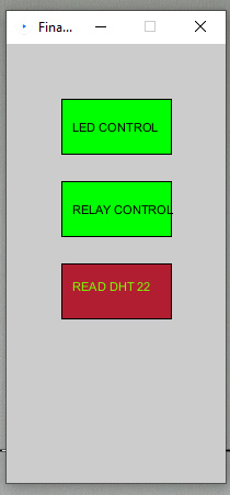
The program will print three buttons. One turns led on / off, one turns motor on, the third prints temperature and humidity values on text screen. I decided not to use time for printing the temperature and humidity values on display, because control should be sufficient in this phase.
The user interface looks like this:

After pressing the buttons (focus on temperature query) the screen looks like this:
The led turns on when button is pressed.
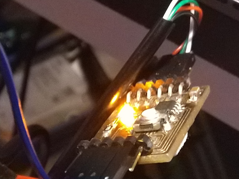
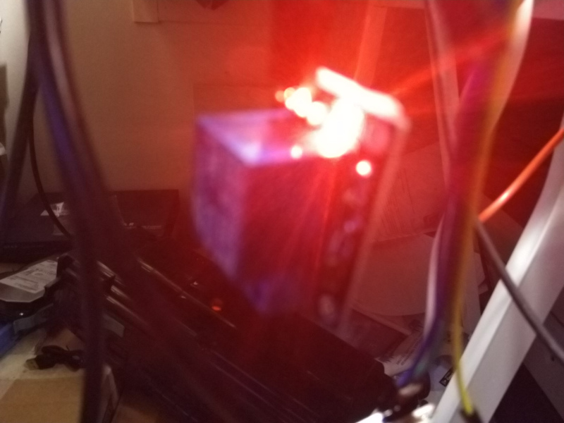
The relay turns on when button is pressed. This suggests that the electrolysys pool can be controlled.
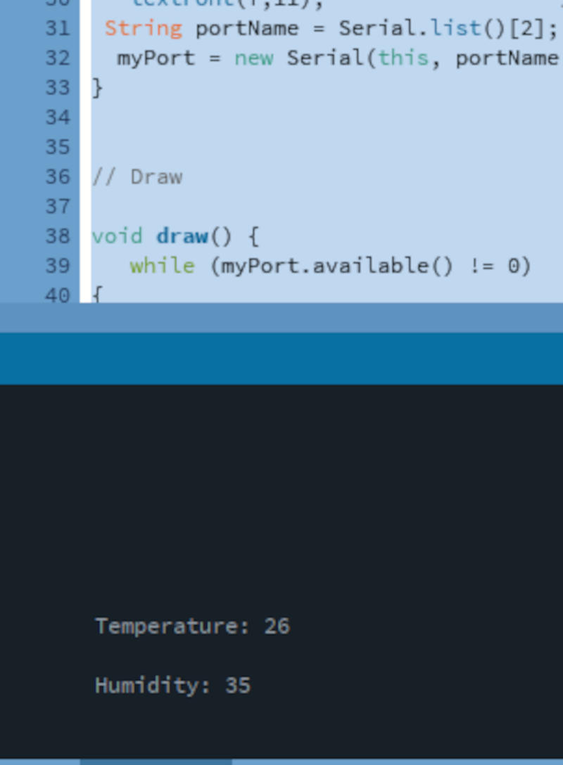
The temperature data is printed on screen:
Conclusion
I have created an application that interfaces a user with an input &/or output device that you made. Code is designed for my final project and will be refined for that.