9. Embedded programming
This week’s assignment consists of a group part and of an individual part.
Group assignment:
-
Compare the performance and development workflows for other architectures
-
Document your work to the group work page and reflect on your individual page what you learned
-
Link to the current version of the group documentation for this week.
Individual assignment:
-
Read the datasheet for your microcontroller
-
Use your programmer to program your board to do something
Learning outcomes of this week are the following: 1) Identify relevant information in a microcontroller datasheet and 2) Implement programming protocols.
The questions to be answered in this page are:
-
Is there a link to the group assignment page?
-
Have I documented what you learned from reading a microcontroller datasheet.
-
Have I programmed your board
-
Have I described the programming process/es you used
-
Have I included my source code
-
Have I included a short ‘hero video’ of your board
Introduction
Making the UPDI programmer is a two-step process. See Programmer UPDI D11C
You need an SWD programmer in order to burn the bootloader
edbg -ebpv -t samd11 -f sam_ba_SAMD11C14A.bin
or in Arduino:
- Select SAMD11C14A as the board in the Fab SAM core, then click on Burn Bootloader. The SWD programmer should be automatically detected.
- Program the USB-to-serial firmware, which can be found here.
The list of the major problems.
There were some problems to solve before it was possible to finish this task.
UPDI Programmer programming pin problem
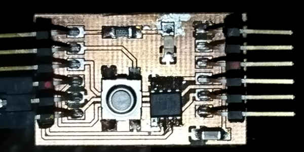
SWD programmers have a 2 pin interface. UPDI programmer we use has two sets of pins. One set is no longer needed after programming the board. It is actually safer to remove the pins. The electronic devices often have some kind of casing in order to avoid damage to the components or damage to other items around the component. The headers of the board were soldered on pads instead of holes. Hole mounting gives mechanical durability to the design. If the surface mounted pin are subjected to too much force, the pads will simply tear off. This is what happened to my board. The removed pins were for programming the programmer itself and strictly speaking were not needed, so the programmer was still functional.
Button problem in the device
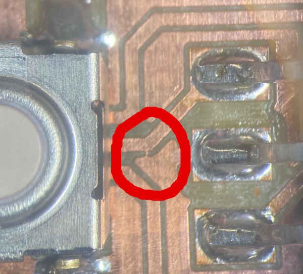
The second problem was the device itself. The button didn’t work correctly. Therefore I tried to replace the button. Unfortunately, I didn’t do it propery and a pad tore off. This required milling and soldering the circuit board again. I also changed the desing a bit. I moved the capacitor to a place where it was easier to solder. I also moved the led to a place, where I think it is more visible. I also changed the design of the broken trace. I could have soldered a wire to replace the broken trace. The new and the old layot are shown in the Week 7 documentation.
Short circuit in the new board
The third problem I had was in the new board. There was a good, old-fashioned short circuit between ground an VCC in it. With the help of the instructor, the problem in the milling was found and resolved. It didn’t cause any damage to the programmer.
Short circuit while programming
The fourth problem appeared when connecting the programmer and the device. There were colored dots in the programmer for finding out where the ground, circuit and data pins are for programming the device. However there were no similar color codes in the wires. Purple and dark blue pins switched places and VCC and ground were short circuited and the contact to the device was lost. This time the chip in the UPDI programmer was fried. This time I heated it with the heating plate and soldered a new chip in place.
This allowed me to program the board. Programming was not covered in the Week 7 documentation, so it was important to do it now.
Tear-off of the programming pins in the UPDI
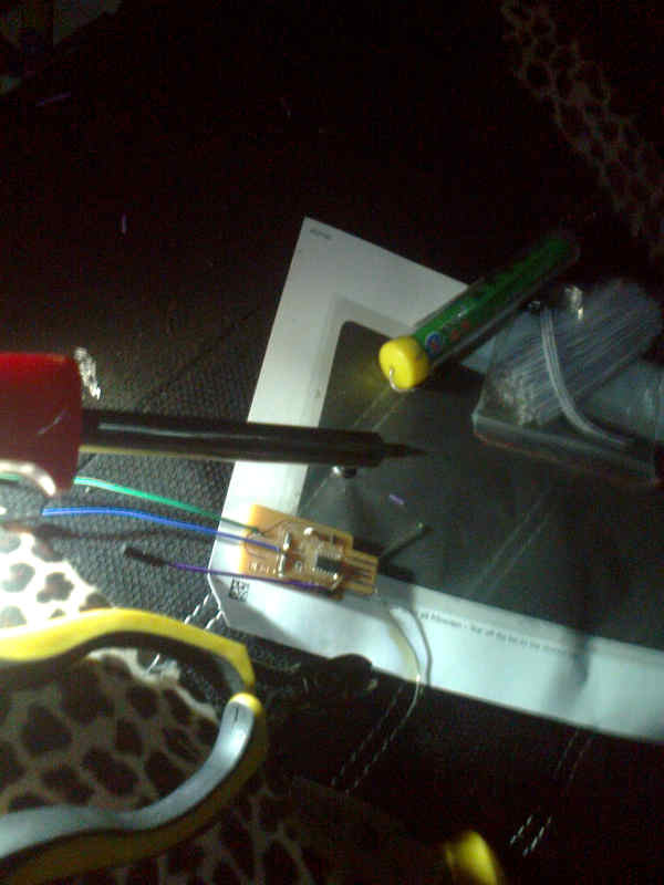
I decided to do the individual programming at home. At the beginning of the Global Open Time I noticed that the programming pins used for programming other devices were also gone. They took the traces with them. I wanted to finalize the individual programming task by Monday, so I had to find a workaround for saving the device. The only soldering iron I found was designed for car use and it has 12V plug. It had no temperature control at all. I also could not find the circuit diagram for the device. I read the USB board pinout for the order of Vcc and Ground pins. The Roland milling machine had cut a bit too much, so after some time I could follow the traces even if the copper was gone with the pins. There was also one pad left, so I could position the connector and find the order of the pins. I decided to solder the wires directly into the board.
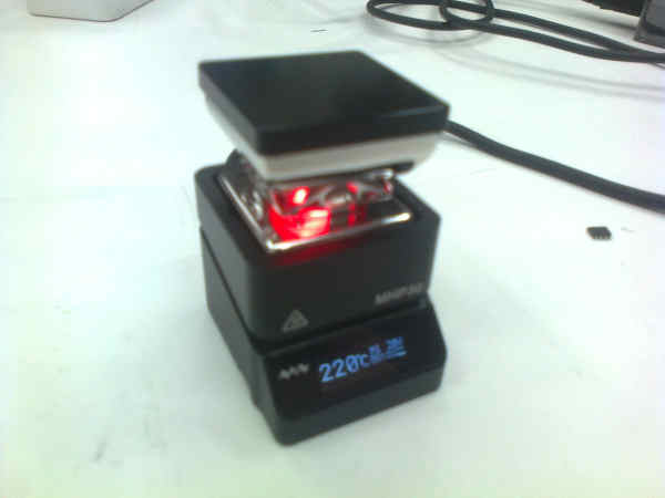
So, I went to a car, used the 12V soldering iron to solder the wires.
Unfortunately the iron was a way too hot for the circuit board material we were using. A trace just burned off. I replaced the burned trace with a leg from a diode. I bent it so that it followed the trace.
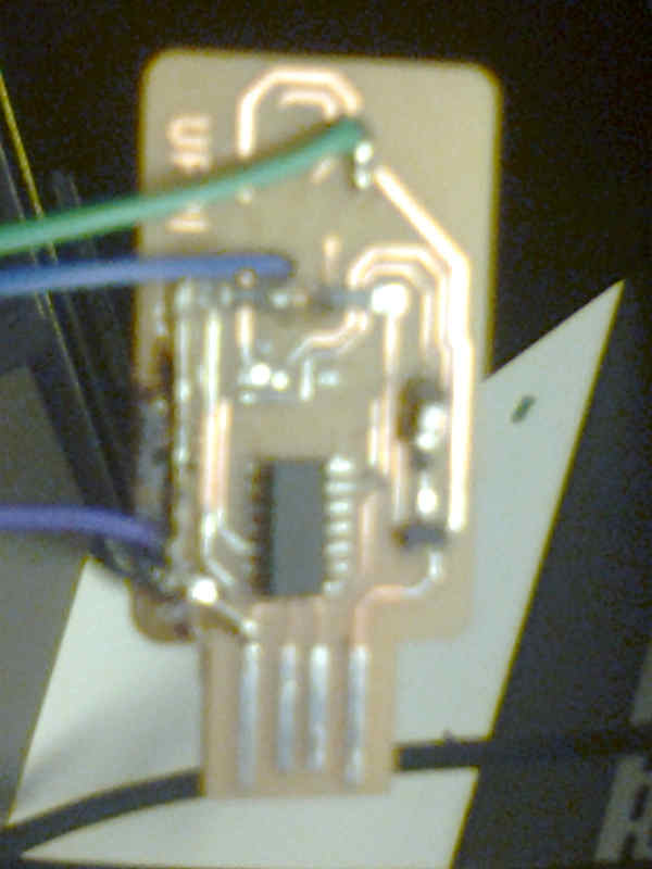
I cooled the soldering iron in snow and ice and installed the device.
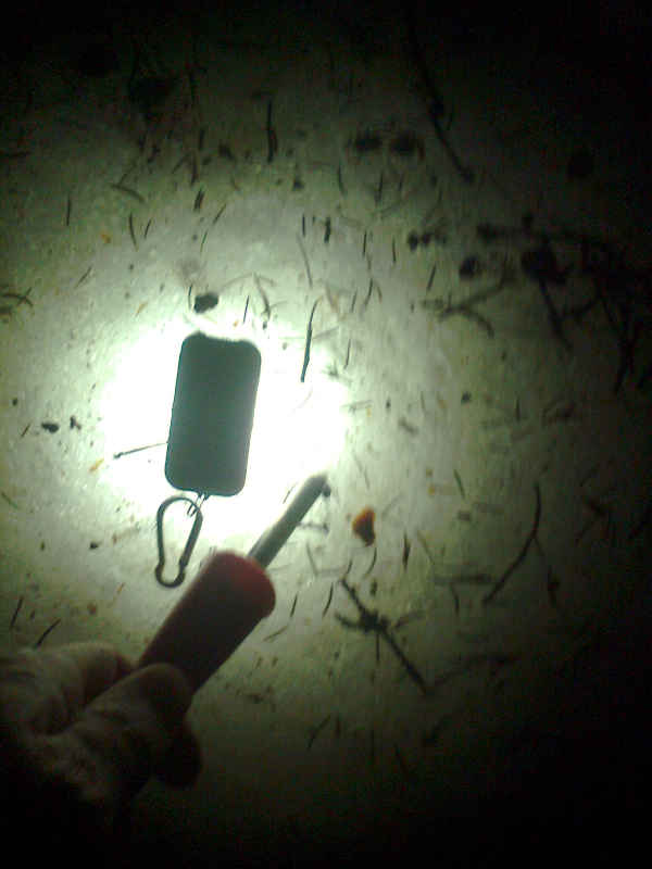
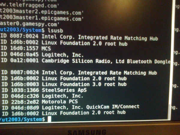
I tested the device. It showed in lsusb.
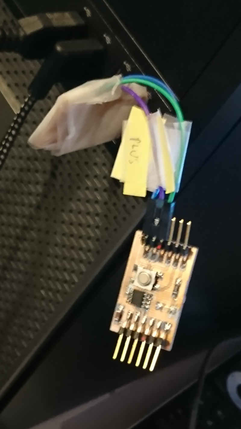
I wrapped the device in tape in order to give the workaround some mechanical strength. Unfortunately I didn’t have proper glue. I also taped pieces of post-it note papers to the wires in order to avoid problems in the future. The board is quite disfigured now, but it works.
Programming the programmer
The programming software can be found from http://taradov.com/bin/edbg/
Then the programmer was inserted in an usb port.
The bootloader for the programmer can be found from https://gitlab.fabcloud.org/pub/programmers/programmer-updi-d11c
I loaded the programmer code. I renamed the programmer.
move '.\edbg-windows-r32(1).exe' edbg.exe
I loaded the code from web page (updi-dc11c page) and programmed the device
./edbg -ebpv -t samd11 -f sam_ba_SAMD11C14A.bin
Programming the device
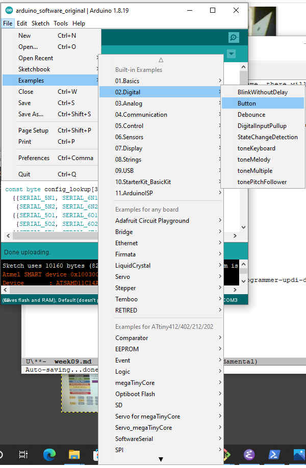
The Arduino IDE can be found from https://downloads.arduino.cc/arduino-1.8.19-windows.exe.
I downloaded Arduino IDE and installed it.
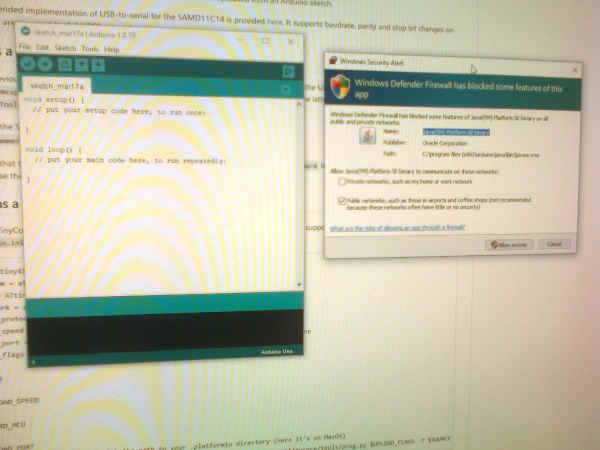
We followed the instructions in https://mtm.cba.mit.edu/2021/2021-10_microcontroller-primer/fab-arduino/.
The Arduino programmer needs some setting up. We needed a FAB sam core. For this … looked for a link for JSON code , copy-pasted it to the Preferences, tools … -> boards manager and installed it.
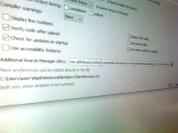
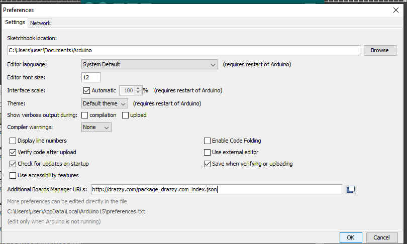
I needed to add https://raw.githubusercontent.com/qbolsee/ArduinoCore-fab-sam/master/json/package_Fab_SAM_index.json to Additional Boards Manager URLs in the Arduino IDE.
I went to Preferences.
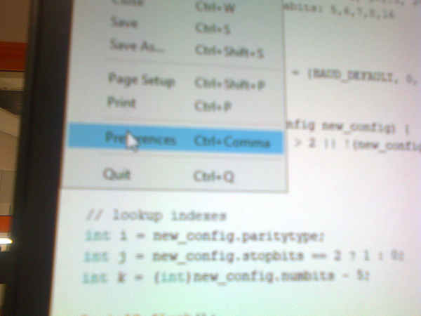
Then I added the URL of the package to the Preferences.
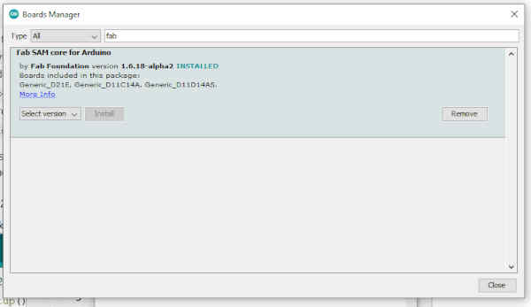
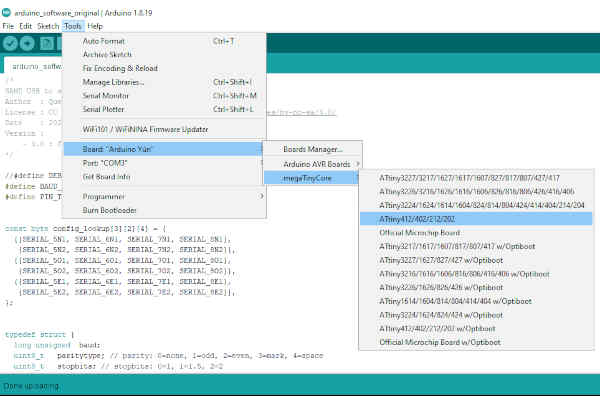
Then I went to tools -> (board) -> Board Managers and installed Fab SAM core for Arduino.
I set the UART settings.
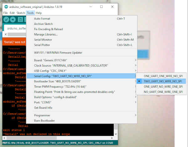
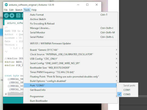
I went to the windows settings and under the devices I found the serial port number for the USB board.
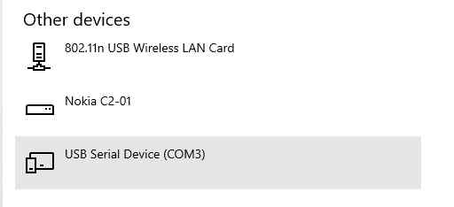
I set the serial port to COM3.
I programmed the UPDI programmer with SAMD11C_serial.
USB-to-serial code is needed for the full support for UPDI.
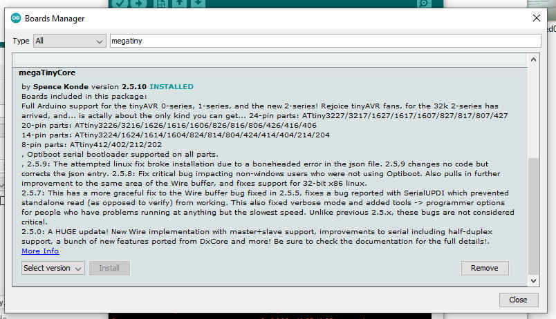
I looked for name megaTinyCore and made a Google search for it. I found https://github.com/SpenceKonde/megaTinyCore.
I added http://drazzy.com/package_drazzy.com_index.json to preferences additional libs and installed megatTinyCore to the Boards Manager.
I selected AtTiny412 board.
Led was installed to pin 3, button to 2. -> 1 and 0 in code.
The pinouts for input and output must be read from the chart. Orange ones are for Arduion IDE. If you use full pin name, there will never be issues. Othwewise you always have to check the images. In an Arduino system looking for the chart with google search appeared to be neccessary.
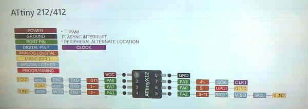
The chart can also be found in https://github.com/SpenceKonde/megaTinyCore/blob/master/megaavr/extras/ATtiny_x12.md.
The pinouts are needed for button demo program:
Two modifications were made for the program.
In function setup buttonpin was changed to INPUT_PULLUP style, pinMode(buttonPin, INPUT_PULLUP);
The button and led pin numbers were set
const int buttonPin = 0; // the number of the pushbutton pin
const int ledPin = 1; // the number of the LED pin
Making my own program
I modified the button test program by adding toggle property and different brighness levels. Editing was done in Arduino studio.
The original program turned on and off if the led was pressed.
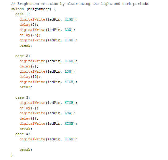
Now the program rotates between four different brightness values when turned on. Button press turns the led off and another button press turns the led on.
The most important parts of the program are 1) the state change part, where the next state is selected, rotating the brightness values.:

2) The brightness part, alternating led on and off with delay.
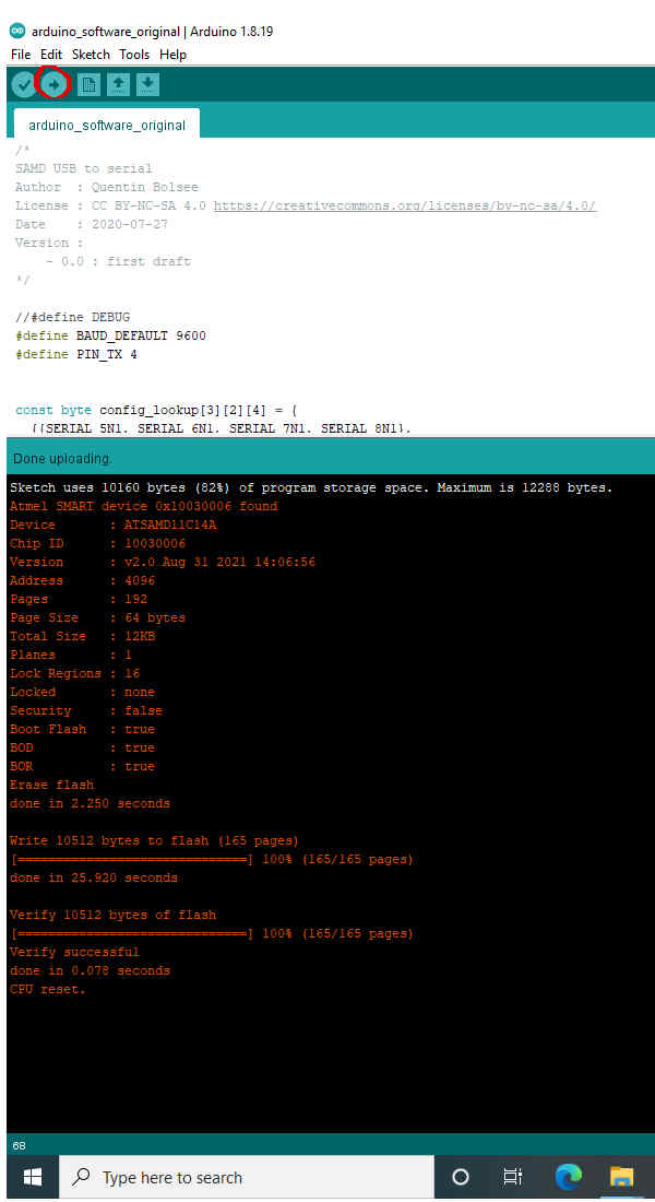
The program compiles with the same settings as the button demo program and uploads automatically with the same settings.
The source code of the file can be found here
Datasheet
I browsed through AtTiny 412 data sheet. The data sheet can be found here. The data sheet has 479 pages. It is a lot of pages.
The basic information of the microcontroller is that it is 8-bit cpu, running up to 20 MHz. There is a 32 kHz oscillator for ultra low power operation. It has a 4 kB of flash and 256 bytes of SRAM and 128 bytes of eeprom in a 8-pin package. These features are quite limited.
The temperature range for AtTiny 412 is from -40 degrees C to 105 degrees C. The CPU can use single power soure. About 5V is fine for all the variations of the CPU.
The AVR RISC CPU has 135 instructions and a hardware multiplier and 32 8-bit registers. The CPU has an internal Voltage reference source (2) and the sources support 0.55V, 1.1V, 1.5V, 2.5V and 4.3V. There are multiple Timer/counters they can do waveform generation, frequency generation, single-slope pulse width modulation and dual slope PWM. There is a Real Time Counter and a Periodical Interrupt Timer. There is an USART which supports a lot of communication modes. There is also a Two-Wire Interface and a 10-bit ADC and a few other nice features.
‘Hero’ video
Here is the hero shot video how the programmed device works.