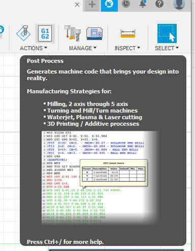
8. Computer controlled machining
This week we did a group assignment and an individual assignment.
Group assignment:
-
Complete your lab’s safety training
-
Test runout, alignment, speeds, feeds, and toolpaths for your machine
-
Document your work to the group work page and reflect on your individual page what you learned
The link to the group assignment page is here.
Individual project
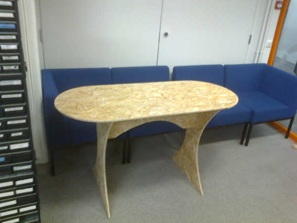
This week’s individual design project is to make (design + mill + assemble) something big. I decided to do a table.
Design something big
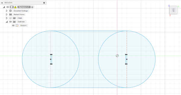
I chose to use Autodesk Fusion 360. I begin by creating a sketch on the XY-plane. I added two circles, a rectangular part between circles and two wide slots for legs.
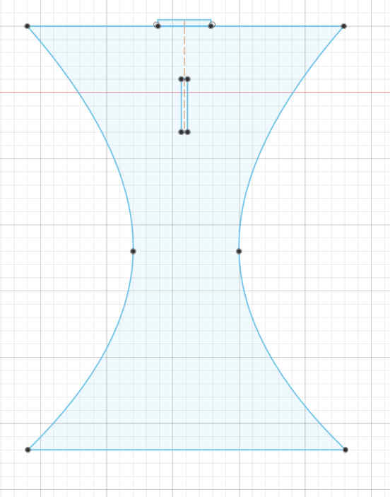
I designed legs by using splines and lines.
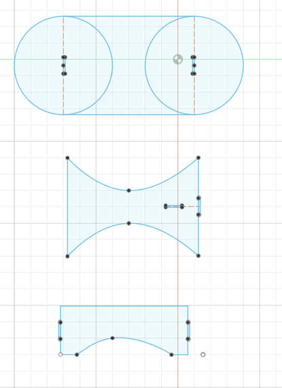
I also designed a support between the legs. Support is not attached to the board plate.
The sketches were extruded and the leg was copy-pasted.
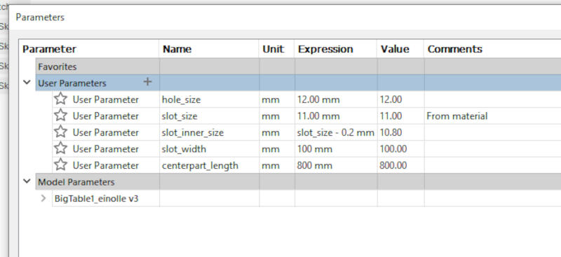
I parametrised the design by replacing some key dimension values with variables.
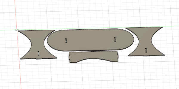
Here is a 3D view of the set.
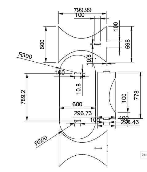
Here are some of the dimensions in the design.
Creating setups
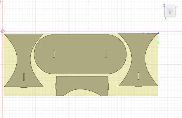
I made a setup for manufacturing the parts. I selected MANUFACTURE from the menu. Then I placed the parts so that they will fit on a single sheet of material.
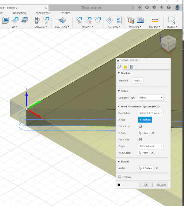
The coordinates and some additional settings must be set. The stock offsets were set to zero. This was done to set the stock is at the same coordinate space as the model.
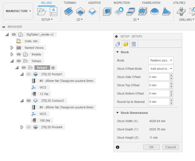
The coordinate axis and origo for milling was positioned on the lower left top corner of the board. The axis were defined according to the milling machine coordinates. The X-axis is sideways and the Y-axis points away from us when we are standing next to the milling machine.
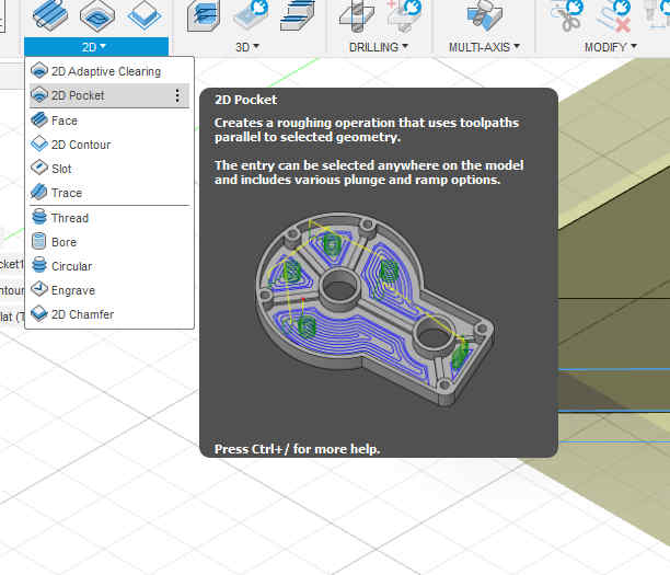
Creating the pockets
I went to Pockets 2D-menu and chose pockets.
Speed and Feed settings
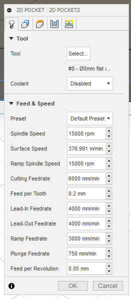
The pocket window opened showing the feed and speed settings.
Spindle speed was set to 15000 rpm, Surface speed was set to 376.991 m/min and the Ramp spindle speed was set to 15000 rpm.
Cutting feedrate was set to 6000 mm/min, Lead-in and Lead-out feedrates were set to 4000 mm/min. Ramp feedrate was set to 3000 mm/min and Plunge feedrate was set to 750 mm/min.
The same speed and feed settings were used everywhere in the design.
Tools selection
Tools can be selected from the Select Tool window. FABLAB_ROUTERI_TOOLS library was already installed, 8mm tasajyrsin puuterä had been selected. The same bit was used everywhere in the design.
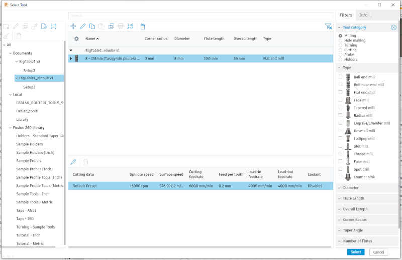
Tools were selected for 2D Pocket1, 2D Contour2 and 2D Pocket2. As already mentioned, 8 mm Flat bit was used for all the selections. Selecting the tool sets the values correctly from the library. The material thickness of the board will be set to 11.00 mm.
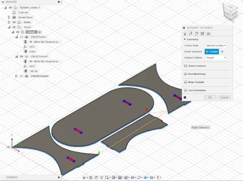
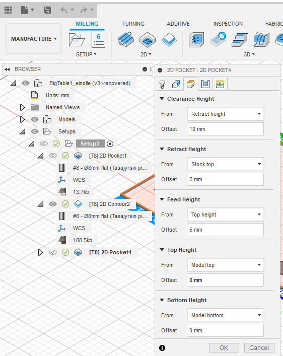
Height settings
I opened the 2D Pocket (2D -> 2D Pocket) and selected all four dogbone designs. I set the Clearance Height to 10 mm offset from the Retract height, Retract height to 1 mm offset from the Stock top, the Feed height to 5 mm Offset from the Top height, the Top height at Model Top level and the Bottom height at Model bottom level.
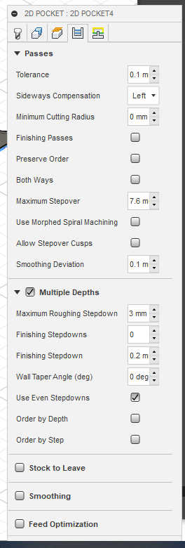
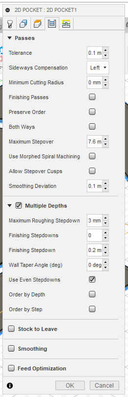
I moved to the fourth tab. I selected Stock to Leave off. I set Multiple Depths on, use even stepdowns and maximum Roughing Stepdown 3 mm.
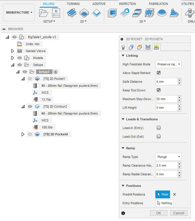
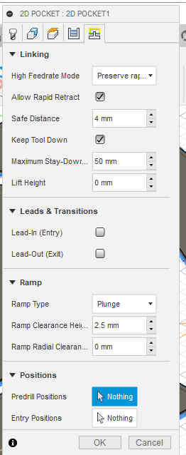
Then I went to the fifth tab and selected lead-in and lead-out off and ramp type to the plunge. Then I pressed OK.
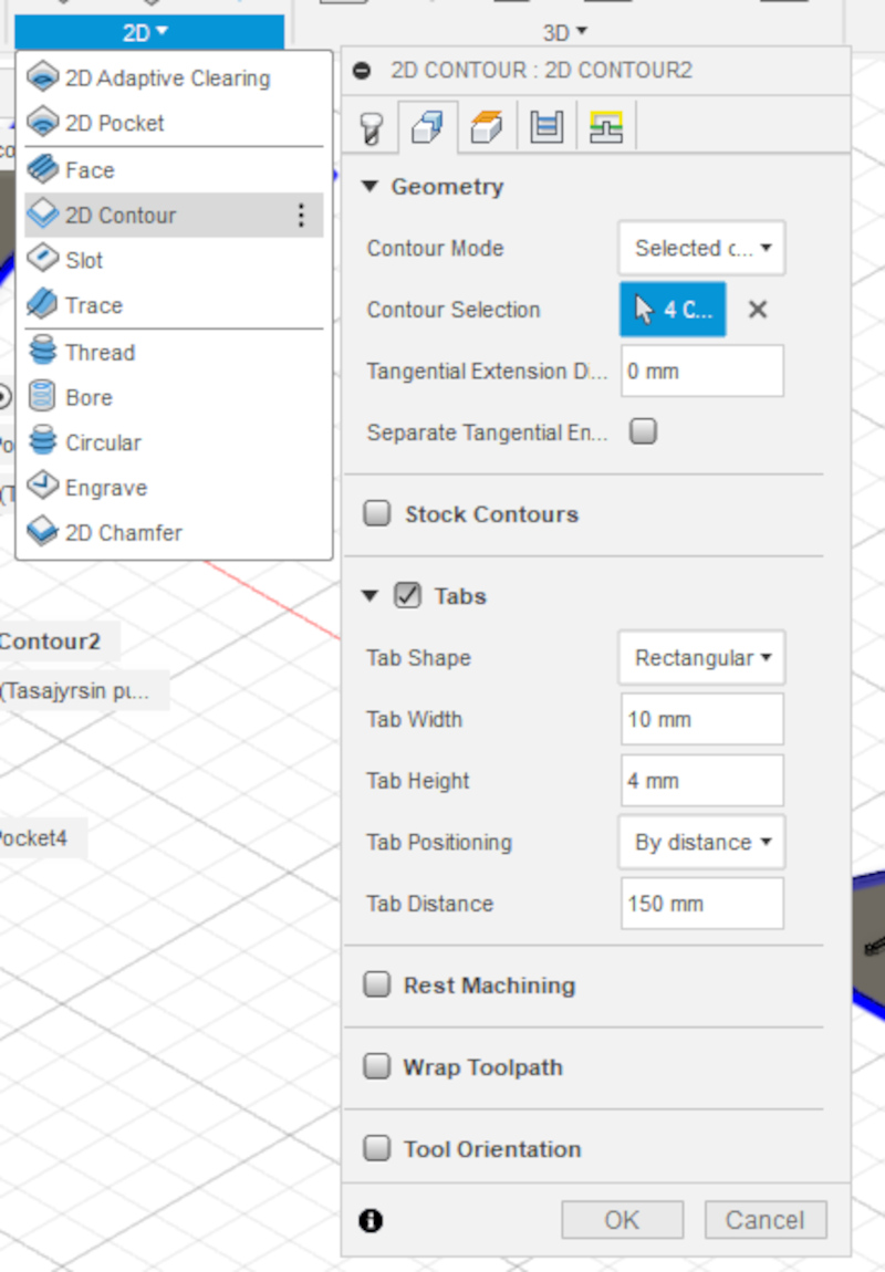
2D Contour
Cutting the 2D contour requires tabs. The tabs keep the parts from moving while they are milled. The selected tab settings can be seen from the image.
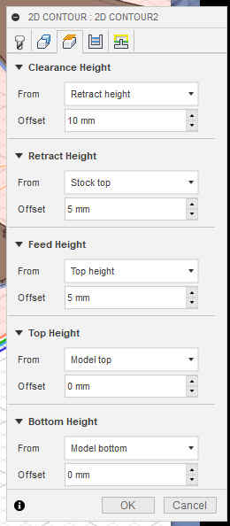
I moved to the third tab, speed and feed settings for 2D Contour. I set the Clearance Height to 10 mm, offset from the Retract height, Retract height to 5 mm offset from the Stock top, the Feed height to 5 mm Offset from the Top height, the Top height at Model Top level and the Bottom height at Model bottom level.
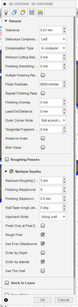
Then I moved to the fourth tab and set Multiple depths, Even stepdowns, Maximum roughing at 3 mm and moved to the last tab
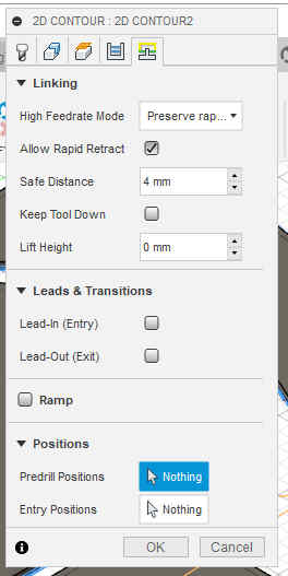
In the last tab I unselected lead in and lead out and pressed OK.
Then I moved to tab 4. I checked Multiple depths, Even stepdowns, set the Max Roughing Stepdown to 3 mm.
Then I moved to tab 5. I unselected Lead-in and Lead-out and changed the Ramp type to Plunge. Then I pressed OK.
Simulation
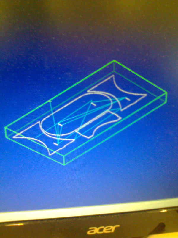
I went to Actions / Simulate and opened the simulation window. Tool, Toolpath and Stock were selected.
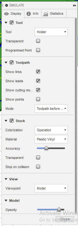
Pressing the play button ran the simulation.
Then I saved the file and sent it to the instructor for comments before milling. Previous iteration had already been seen by the instructor and it only had required changes in the toolpaths.
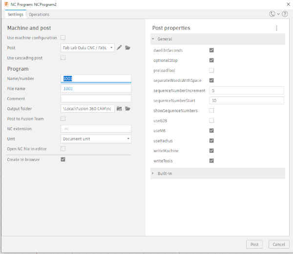
With instructor’s help, we made a couple of changes to the settings. Then we simulated the milling again and created a NC file.
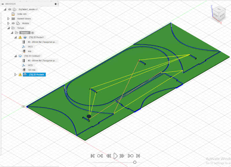
There were warning messages (yellow triangles) about features that were not milled I asked instructor if they are something to pay attention to, but he told to ignore them.
I uploaded the files, nc milling file and the desing file to the repo:
-
BigTable nc file.
-
BigTable Autodesk file.
Milling
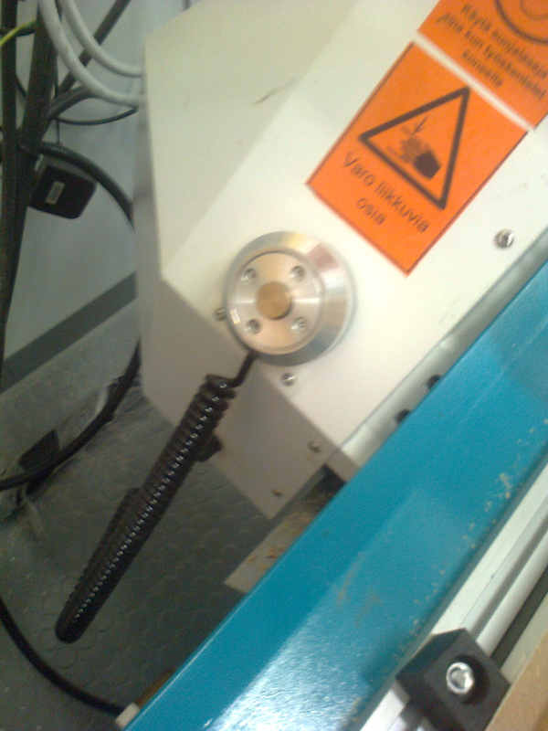
I removed the cover from the milling head my opening the two screws.
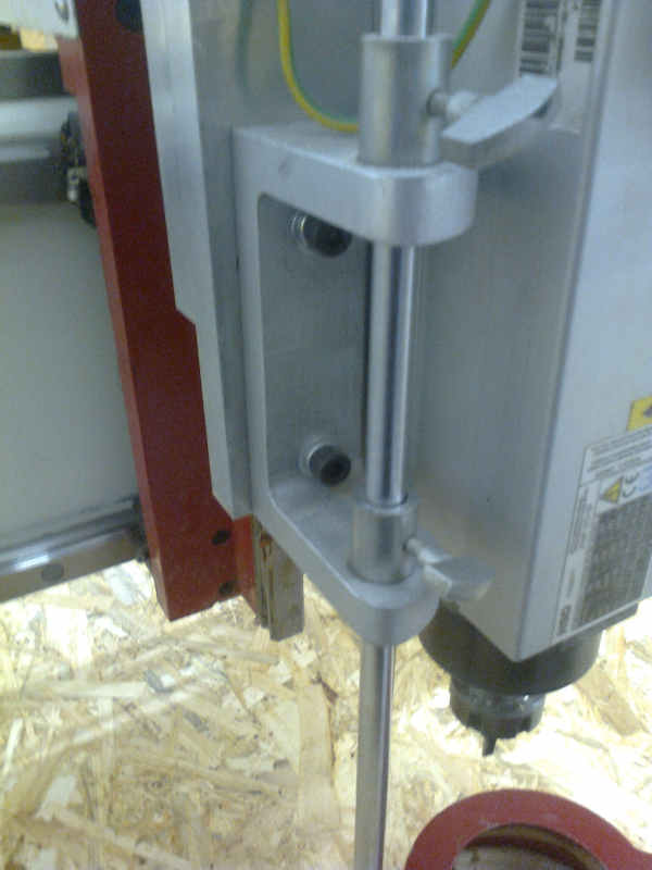
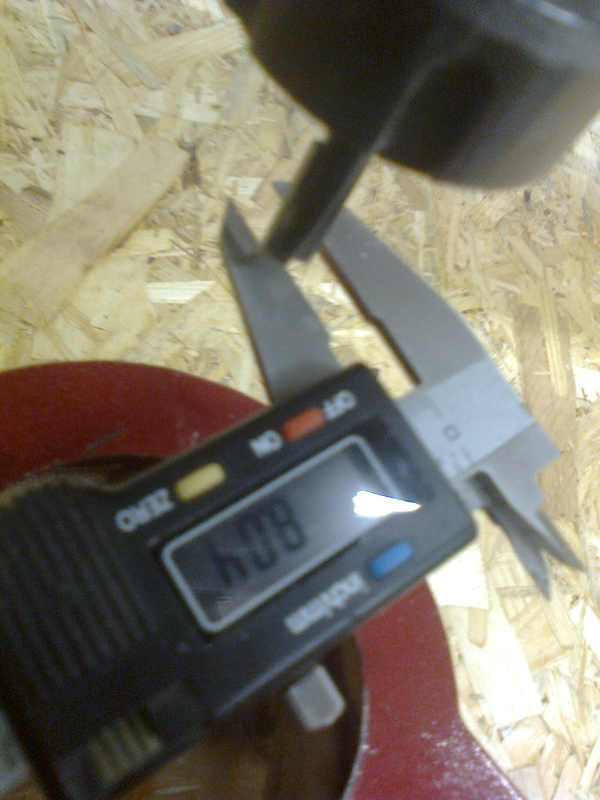
Then I examined and measured the milling bit in order to make sure that it is 8 mm flat head. The measurement confirmed it.
We moved the material to the milling board.
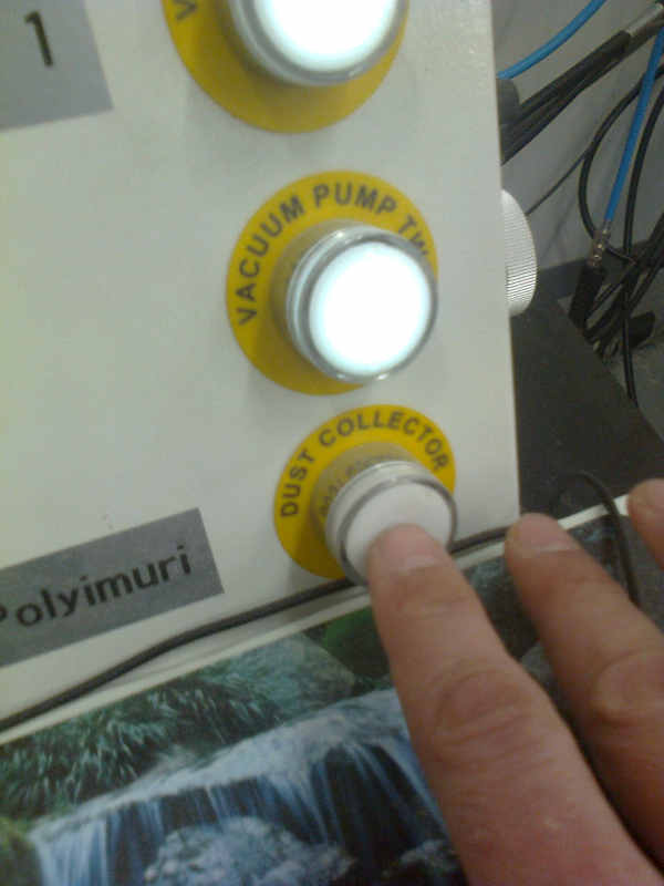
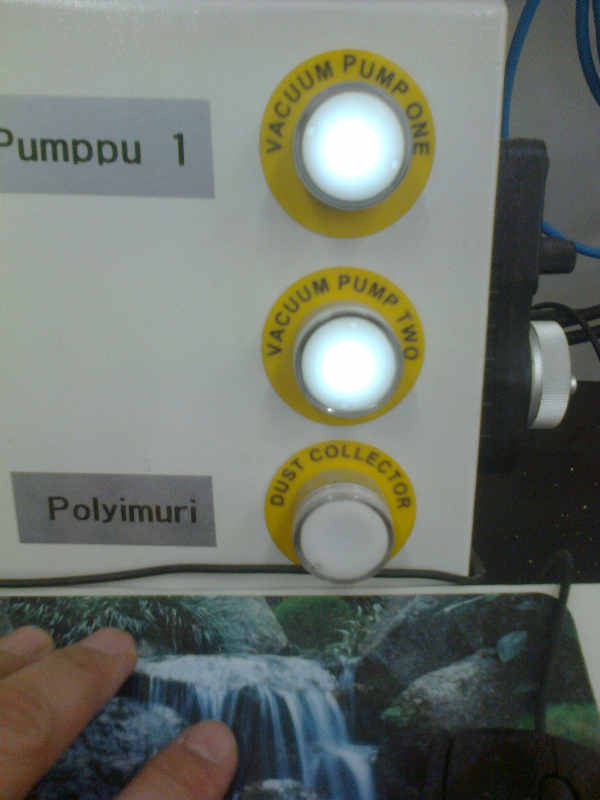
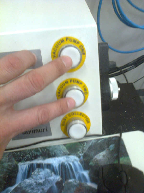
I turned on the vacuum pump. The board was now firmly fixed.
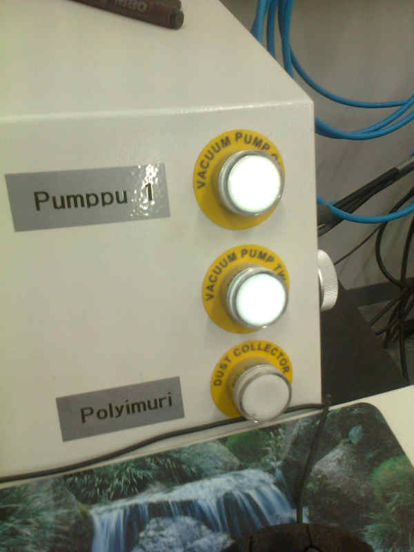
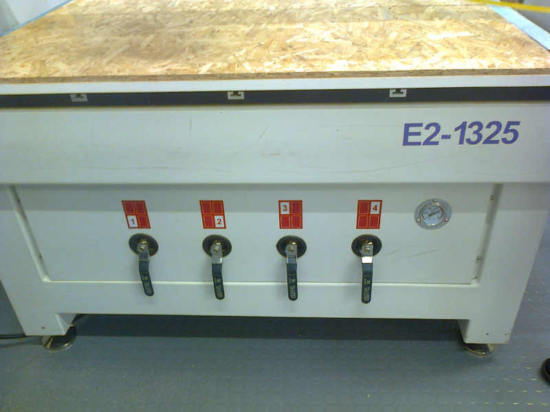
All the four valves were opened for this big job.
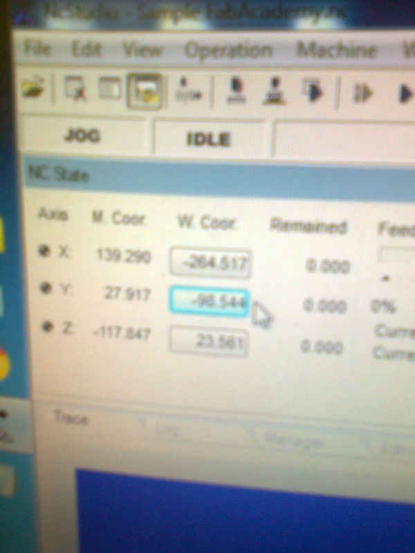
I used the controls on the program to move the milling head for adjusting the x, y and z coordinates.
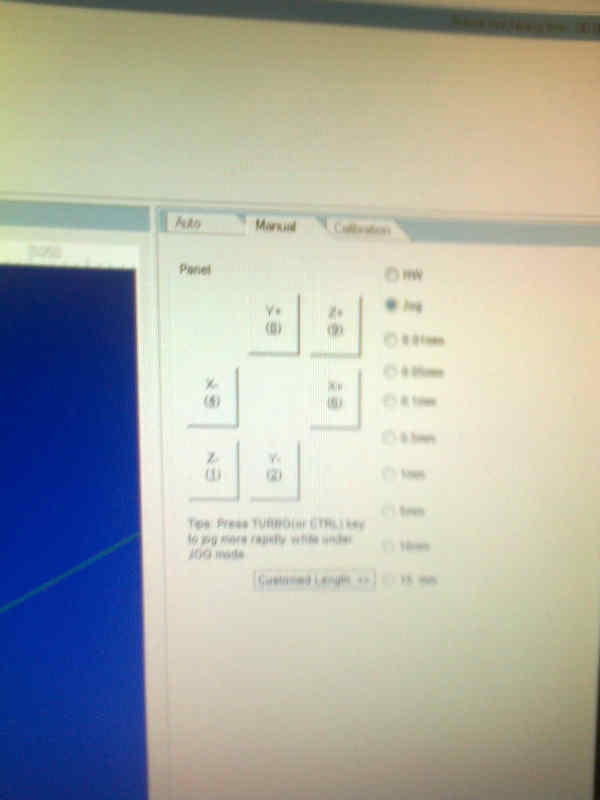
I moved the head to a good starting position close to nearer left corner of the board. Then I reset the board coordinates by clicking the values and accepting.
For calibrating the Z coordinate, the Mobile Calibration Tool was used.
The head was moved to a good position for calibration and the mobile calibration tool was placed under the bit. The bit was lowered a bit in order to verify the location over the calibration tool.
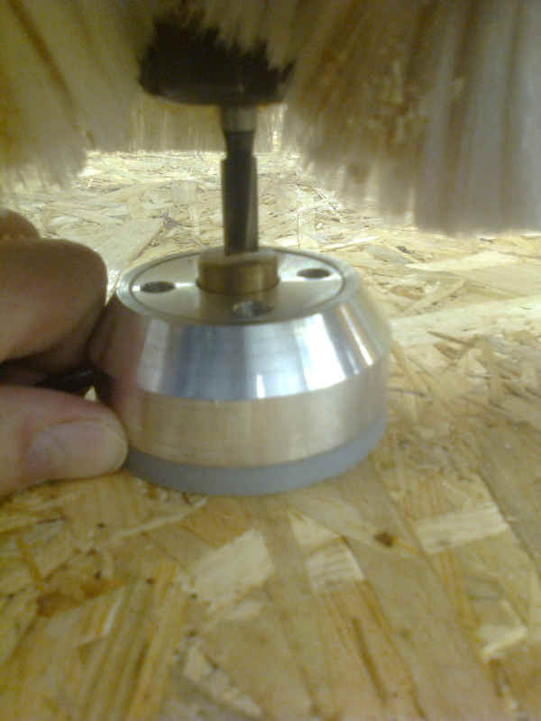
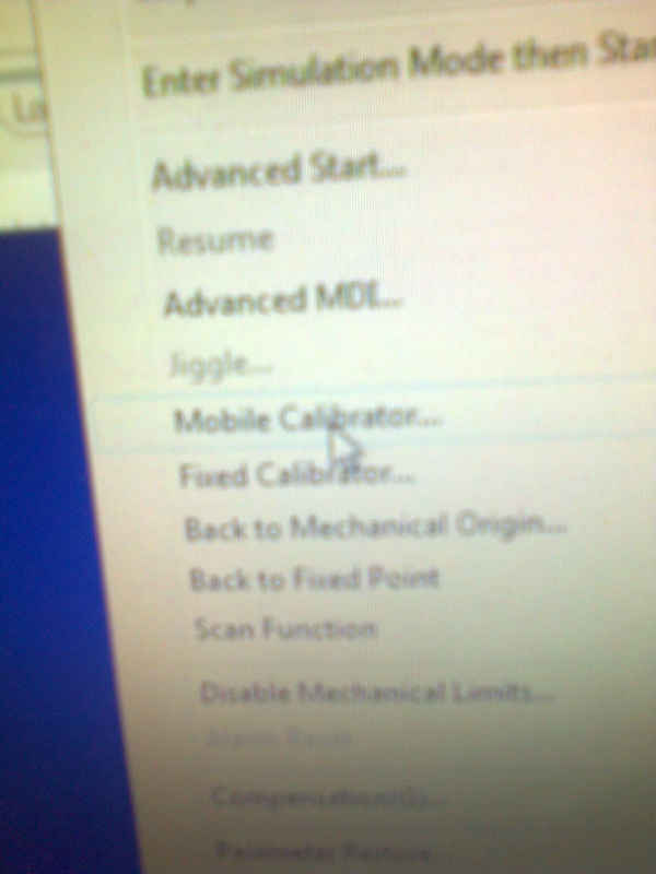
Mobile Calibrator was selected under the Operations menu and the calibration was started. The calibration tool was hold in its position by hand.
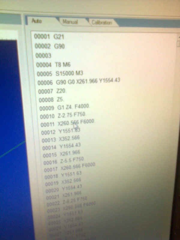
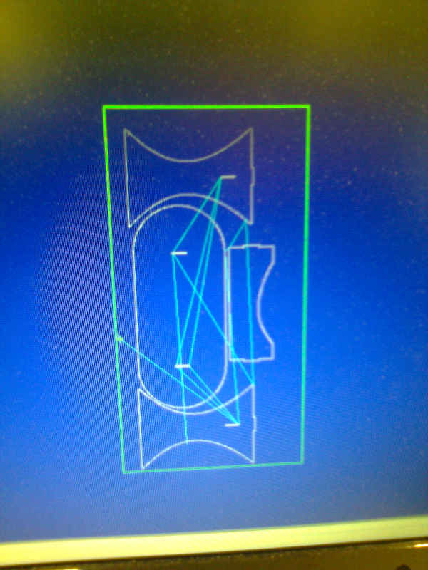
The NC-file was loaded.
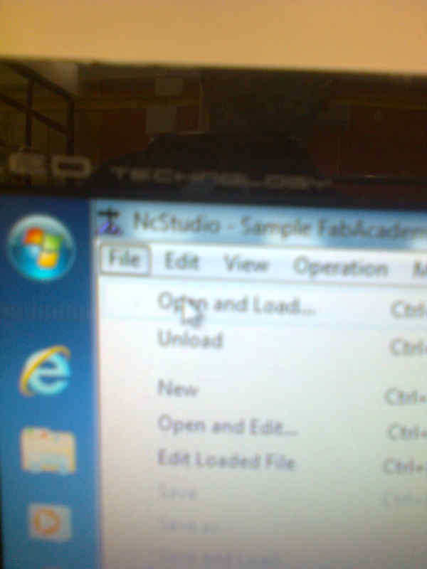
NC-file was found under the Auto-tab. It looked legit.
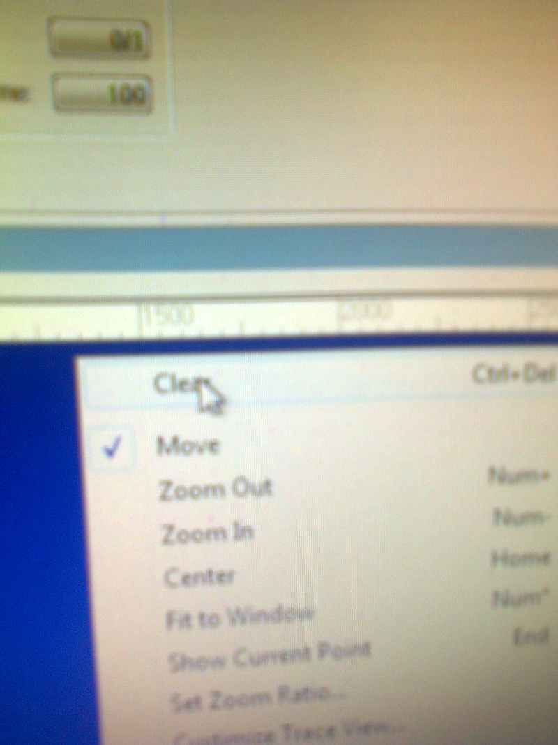
There was something on the simulation display. There are three ways to clear the simulation display. Keyboard shortcut (CTRL + DEL) clears the simulation display. Choosing Edit -> Clear view (or corresponding menu icon down from the Edit menu.) clears the simulation display. What I did, I moved the mouse over the simulation window, pressed the right mouse button and cleared the simulation screen by selecting Clear in the opening window.
A new simulation was started by pressing the smaller play button.
The simulation completed and the result was inspected with instructor and it looked ok.
The dust collector was turned on.
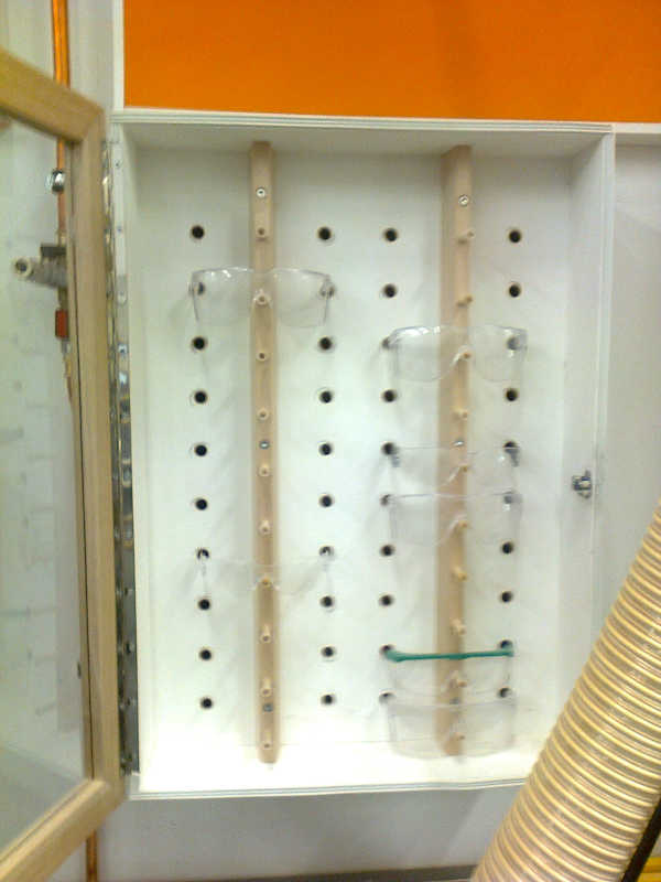
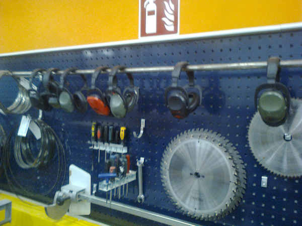
Safety equipment was located and put on.
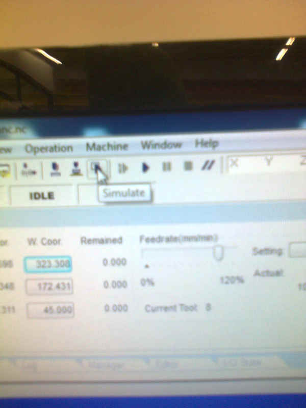
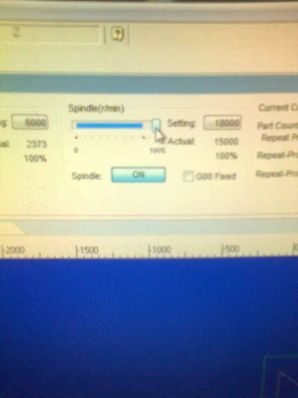
Feedrate and the spindle speed were set on 80%.
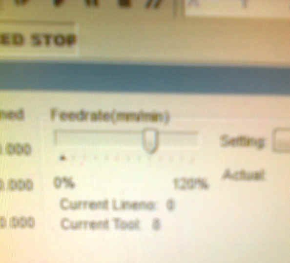
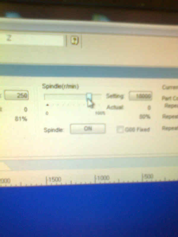
Note that in the images the actual speed rate and feed rate were zero, because the milling had not started yet. I assume, that the 80% is calculated from the rates given in the nc file. This would result 4800 mm/min feed rate and 12000 rpm spindle speed rate right after the set speeds were reached.
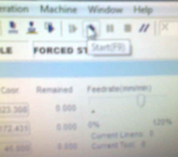
The milling was started.
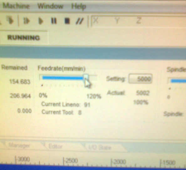
After the milling has started succesfully and everything appeared to be working nominally, feedrate and spindle speed were adjusted to 100%. These speeds appeared to be 6000 mm/min feed rate and actual 15000 rpm spindle speed. Note that in the design the feed rate was also 6000 mm/min, but the spindle speed was set to 15000 rpm. In the image, the set spindle speed rate was 18000 rpm, but the actual speed rate was the designed 15000 rpm.
The milling progressed as it should.
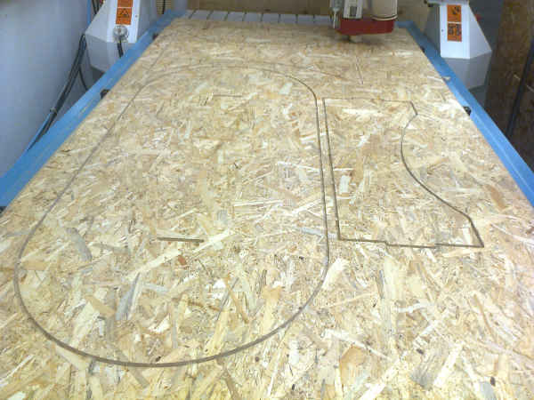
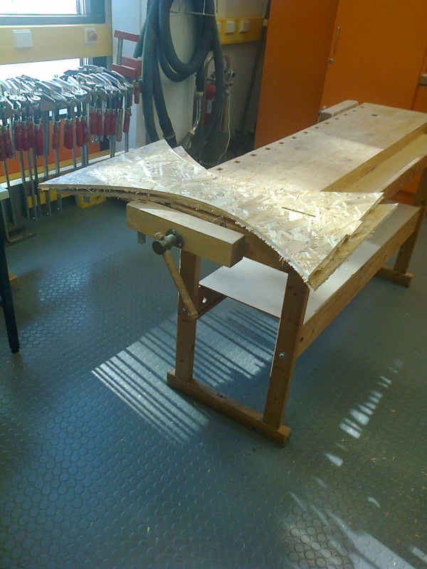
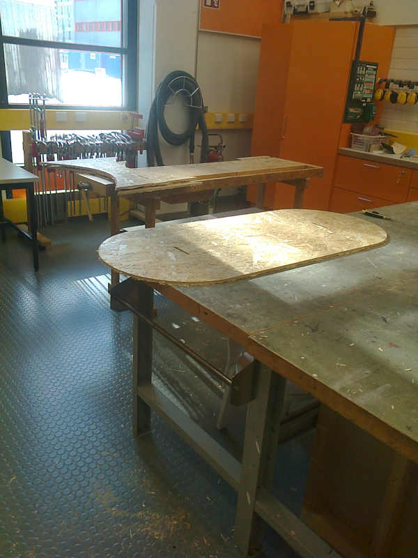
After milling the board was removed and moved to the next room. In the room, there were the required tools for cleaning the parts.
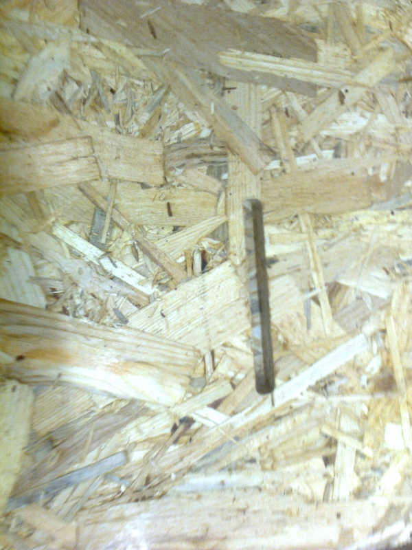
The dogbone structures were not milled correctly.
The vacuum pumps and the dust collector were shut down.
The computer was shut down. After the computer was shut down, the power was switched off.
I was shown a sanding machine to use for finishing the products.
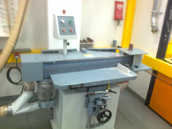
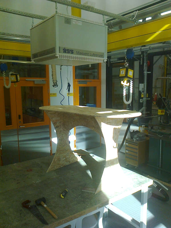
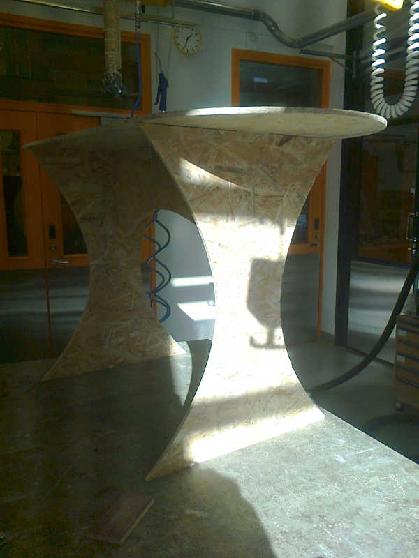
The separate parts were sanded and the support parts were cut off.
The table was assembled. Assembling required some sanding. The table stands without screws or glue, but I sanded a bit too much from one place. Glue was not used, because I need to move the furniture, but screws or glue is needed in order to use it, or it can’t take weight.
What did I learn?
After assembling the table, I returned the tools to their locations, as far as I could remember where there are. I carefully used vacuum cleaner to remove the sawdust. Because the material we used, it was everywhere. I didn’t know what to do with remaining parts of the board. I was asked to go back and use a saw machine in order to cut the board to small enough pieces for trash bags. The manager had complained about the things I had left there.
I asked and got a short safety teaching for the machine (“don’t cut your fingers”). I put on the safety gear, sawed the parts, vacuumed the sawdust and asked, if the result was acceptable.
I recommend that in the future, the instruction how to clean up and where to put the garbage is included in teaching. The saw machine was the most dangerous equipment in the whole week, so if we were supposed to use it, then there should be some training about it.
I learned how to use the NC-milling machine. I learned how to design the toolpaths. I learned to check the hole sizes against the milling bit size when making the dogbone structures. Because this design is parametrically made. If the design were done correctly, this could be done simply by changing the parameter for the radius in the list.
I also learned not to make holes smaller than what I can mill with the bit available.
Dogbone structure problem
The dogbone structure could be repaired by increasing the size of the holes in the design. I combined the elements while sketcing the structure. That was probably unnecessary and only made repairs more complicated. In some more advanced CAD programs, the Sketch workflow is saved, but not in the Autodesk Fusion 360. Therefore fixing the mistakes made in the sketch is more difficult. The group work example design didn’t combine circles with other elements and I begin to think that I shouldn’t have done it either. My solution to the problem would be a redesign for the dogbone structure as it was done in the groupwork example.