4. Computer controlled cutting
This weeks individual assignment is to: - Design, lasercut, and document a parametric press-fit construction kit, which can be assembled in multiple ways. Account for the lasercutter kerf and cut something on the vinylcutter.
Learning outcomes
- Demonstrate and describe parametric 2D modelling processes.
- Identify and explain processes involved in using the laser cutter.
- Develop, evaluate and construct the parametric construction kit
- Identify and explain processes involved in using the vinyl cutter.
Questions that are answered in this assignment
- Is there a link to the group assignment page? Yes, there is a group assignment page.
- How did I parametrically designed the files?
- How did I make my press-fit kit?
- How did I make my vinyl cutting?
- Did I include my original design files?
- Did I included the hero shots?
Links to the deliverables / files:
- .stl file of the construction kit (the two repeating pieces only version) is available here.
- Fusion 360 .f3d file of the construction kit is available here.
- Adobe Acrobat .pdf file for the kit is available here.
- .svg vector file for vinyl cutting is available here.
Individual task
The individual task consists of two parts: laser cutter part and the vinyl cutting part. I decided to combine the parts.
I made an initial attempt to do the individual task. I decided against completing it and started from the scratch instead.
I decided to use Autodesk Fusion 360 for the task.
Operating the lasercutter and the safety of the laser cutter,
The safety and how to operate the laser cutter is covered by the group assignment page for this week. For more information see also
-
Link to the instructions how to operate the laser cutter in Fab Lab Oulu Wiki Space (FLOWS).
-
Link to the safety instructions of Fablab Oulu, including the safety instructions for the Laser Cutter.
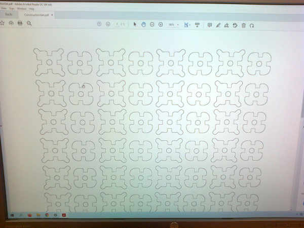
Design of the lasercut set
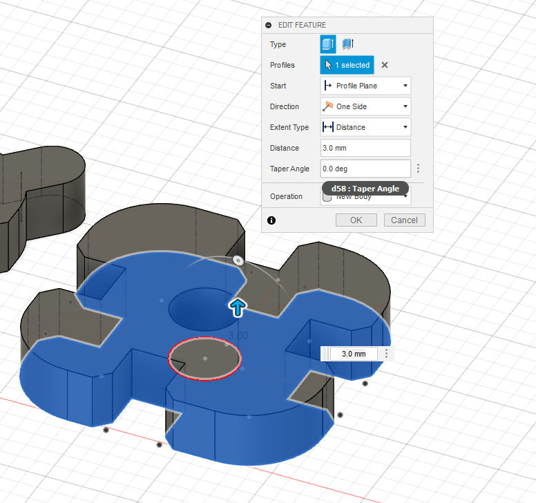
I created a sketch and chose xy-plane for the base pplane for the sketch. I began with two squares (Create -> Rectangle). For one square I filleted the corners of the square (Modify -> Fillet) with a parameter and added the slots by adding a rectangle (Create -> Rectangle) constraining the rectangle, selecting outer lines with the mouse and deleting the outer line of the rectangle. The slots were chamfered (Modify -> Chamfer -> Equal Distance Chamfer) with a parameter for making the assembly easier. For another square I added small circles (Create -> Circle) with parameter as extensions to the corners and conneted the circles with constrained lines (Create -> Line) to the main body. I parametrized the designs by exchanging the main design parameters with parametric values. I also created centered circles in the center of the design (*Create -> Circle -> Center diameter circle). I didn’t parametrise it but put a fixed value for it, because it wasn’t initially meant to me a construction element by design.
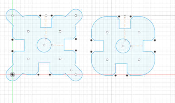
I added parametres in the design. The idea was to be able to resize the squares if neccessary.
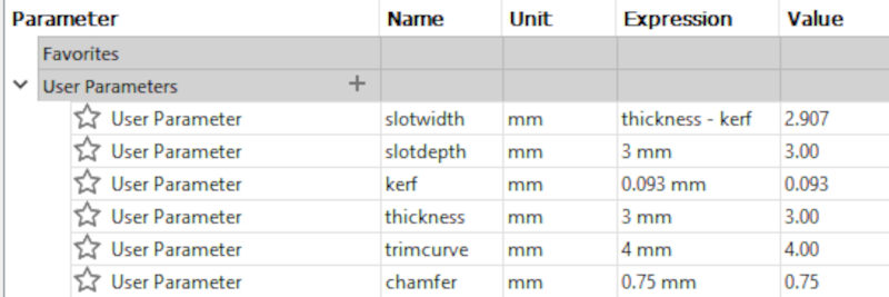
The parameters I used are: 1) slotwidth. This is the widht of the slot. This is the thickness of the material (thickness parameter) substracted with kerf. 2) slotdepth. This is the depth of the slot. This is not affected by kerf. 3) kerf. The effect of the laser beam width to the material used for cutting. I tested first the kerf calculated in the group work (before correcting the value) and then estimated the difference to the right value by measuring, ending up to an estimate of 0.093 mm. I am now fully aware that this is not the right way to do it, but it produced somehow acceptable results. The fit could have been tighter without causing any problems.
Kerf had to be accounted in the slots, which were the main connecting structures between pieces. If kerf was not accounted, the fit would have been too loose and the construction of models with the pieces would not been possible.
The kerf was not accounted with extensions and holes. It is possible to build by using these features as well, but it is more by good luck than by design. Compare this to Lego brics, which also have “illegal” ways to build structures.
4) thickness was the material thickness used in cutting (3.0 mm). 5) trimcurve is a parameter designed to be used in trimming. 6) chamfer is the parameter designed to be used in chamferring the slots.
The sketches with parameters:
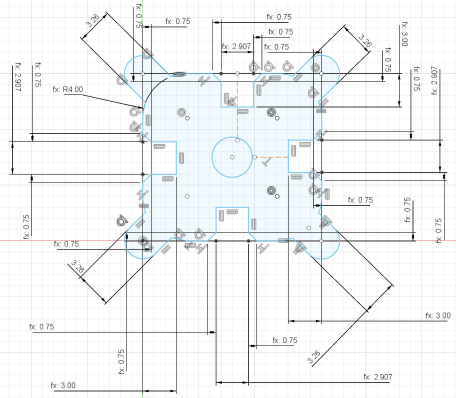
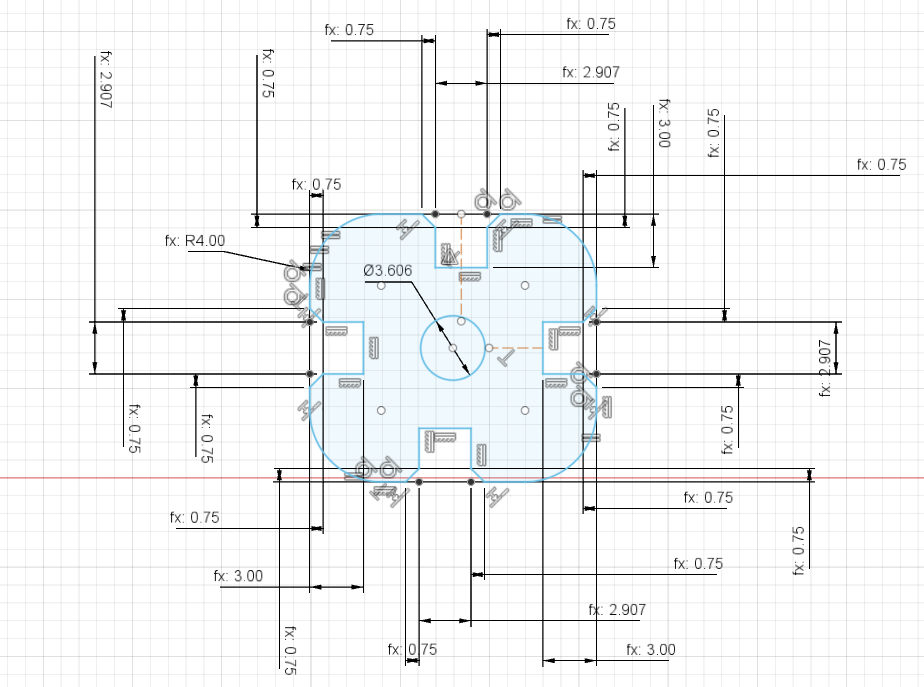
I extruded the sketches to bodies one by one by 3.0mm by using Create -> Extrude.

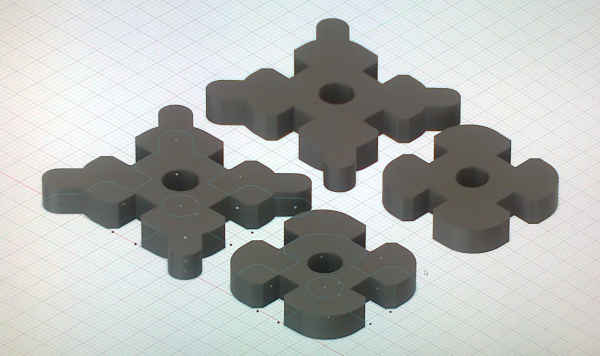
I copied the bodies with mouse select and move (M key) in order to make a set.

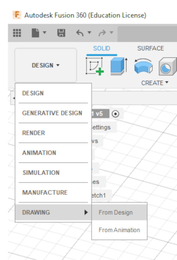
I created a drawing from the design by selecting Drawing from menu.
I removed all the exra information from the drawing.
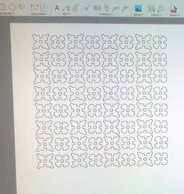
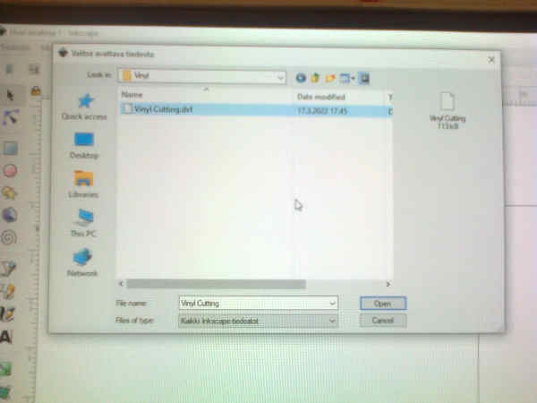
I exported the file as a DXF file by File -> Export* and by choosing .dfx as the file type.
Then imported the file in Inkscape.
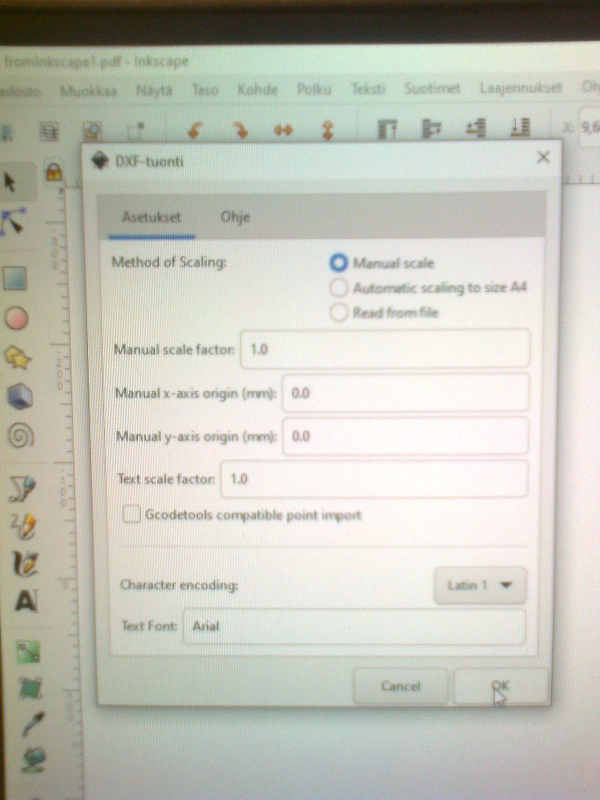
I selected the lines and changed the line width to 0.020 mm. The document was then saved as pdf on USB stick and transfered to lasercutter control computer.
LaserCutting the set.
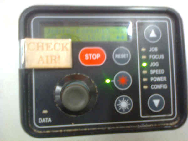
Lasercutter was turned on and the air valves were set as they should.
USB stick was insterted to the laser cutter control computer. 3mm MDF material was placed on the laser cutter table.
Calibration tool was used for calibrating the z-coordinate. Jog was used for moving the laser head to the suitable starting site. The origin is top left. Starting location x/y coordinates were confirmed by pressing the control stick.
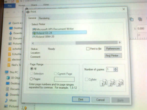
After the starting location was set, file was opened as pdf and the print-command was issued.
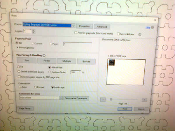
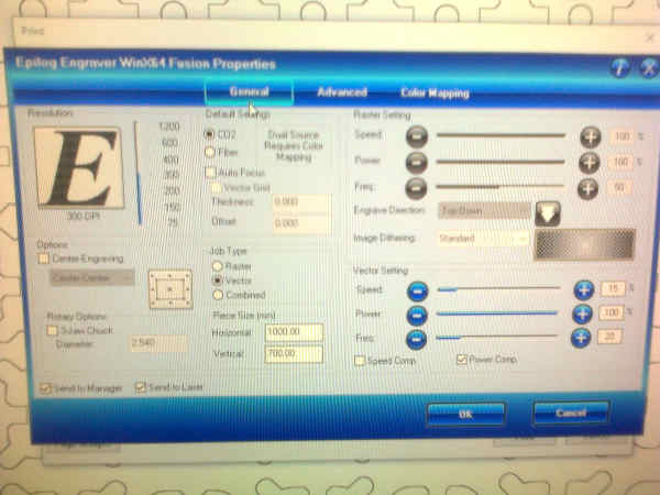
3mm MDF cut was selected in printer advanced settings.

The settings were changed and the printer driver was ready to print.
The clearly visible print button was pressed and the print job was sent to the printer sercer of the lasercutter.
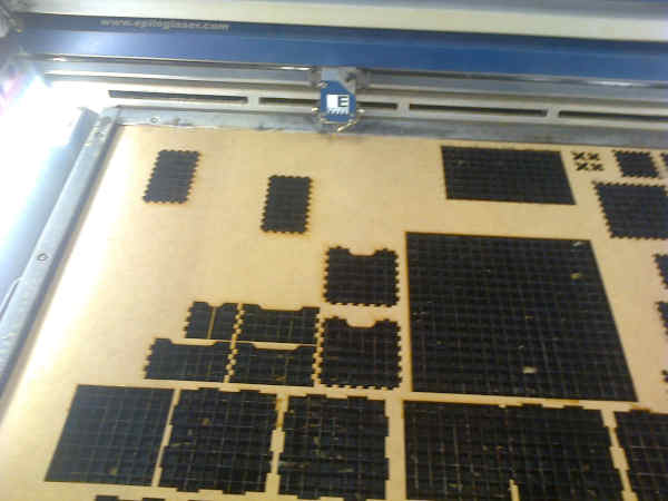
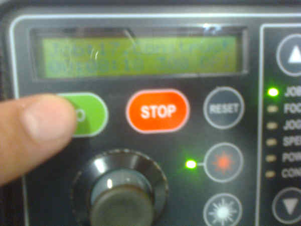
In the lasercutter, correct job was selected on the cutter and green button was pressed in order to begin the cutting process.
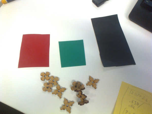
Enough pieces were cut for the construction kit. After the pieces were cut, the safety required 30 seconds of waiting before opening the lid.
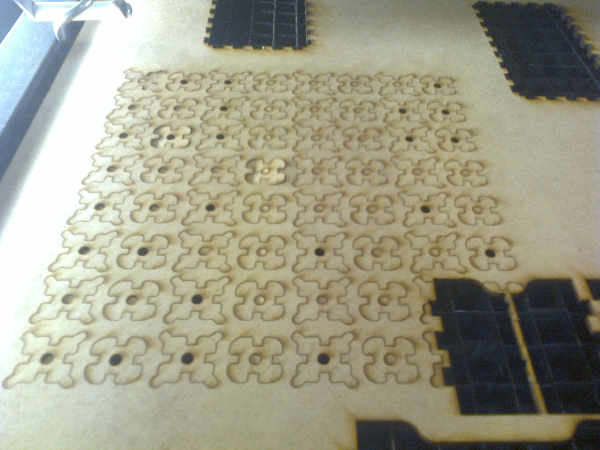
A few extra pieces were cut to cover the missing pieces. The extra material was removed and the material was removed from the cutter.
Vinyl cutter
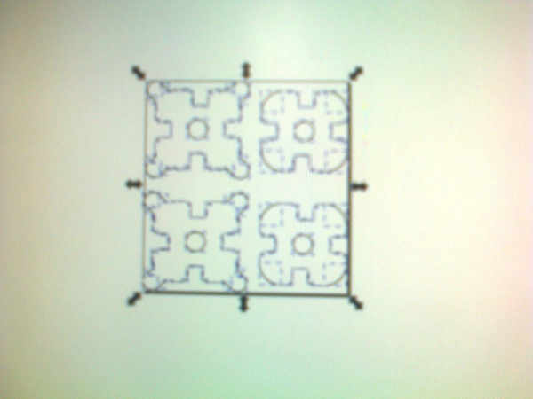
The dxf file containing four faces for construction set pieces was made as dfx file. The file was imported in InkScape.
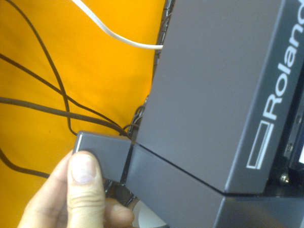
I turned on the machine.
It is important to move the pich rollers to the areas marked white on the printer.
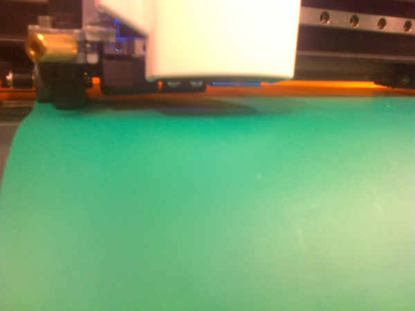
I opened the latch and inserted a piece of vinyl and aligned it so that the rolls can move it. The pinch rollers were moved to areas marked white. I closed the latch.
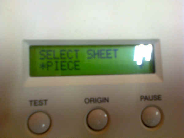
I selected the sheet size as piece.
I moved the head to the right position with cursor and pressed origin.
I went to printing preferences and pressed Get Machine on the size preference tab. The cutter can scan the piece of vinyl and give dimensions of the piece.
The correct printable area was selected.
Print command was issued to the vinyl cutter.
The vinyl was cut
After the cutting, the latch can be opened and printer head moved avay.
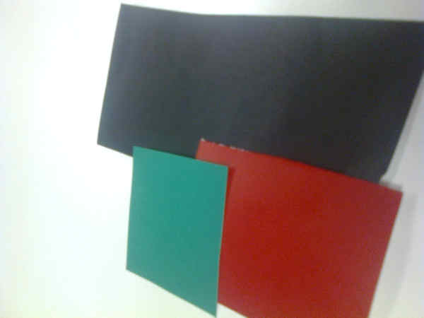
The process was repeated for black and red material.
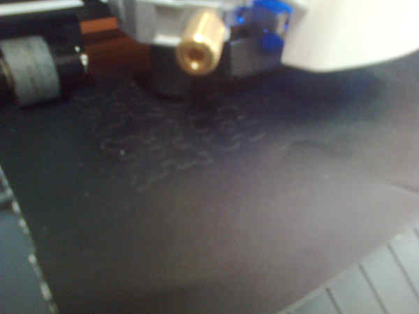
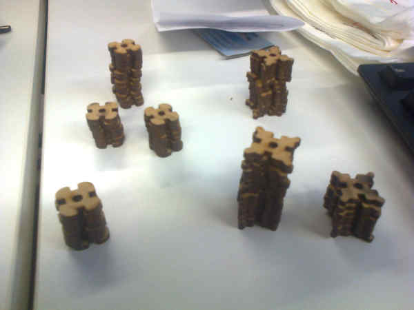
After the vinyl was cut, the shapes will be inserted over the construction kit pieces. I just removed the pieced by bending the material and pushed the vinyl afainst the pieces and there were no problems in removing the pieces. I didn’t use transfer sheets.
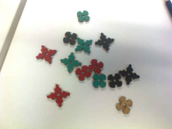
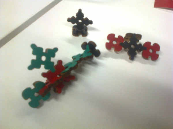
The pieces can be used in constructiong many different shapes.
What did I learn?
I learned about kerf. I learned how to use the Roland GS-24 vinyl cutter. I learned about safety. I learned how to create cuttable PDFs and about the requieed line width. I also learned how to make texture with a laser cutter.
I had a lot of problems. It appears, that I basically had to do again or learn again from the other sources most of the things we studied during the instructed group work. I probably could have been more systematic with the constraints used in the design.