3. Computer Aided design
This week’s aim is to model (raster,vector, 2D, 3D, render, animate, simulate, …) a possible final project, compress the images and video and post it on my class page. The learning outcomes are to evaluate and select 2D and 3D software. I also will demonstrate and describe processes used in modeling with 2D and 3D software.
The questions I should answer are 1) if I have modeled experimental objects/part of a possible project in 2D and 3D software, 2) shown how I did it with words/images/screenshot and include my original design files.
Selection of the software
At this point, without a dedicated working Windows machine, I chose to test OpenSCAD as an interesting Linux alternative with a promising programming model and OnShape because it is cloud based. FreeCad also had Linux support, so I tried it as well. Krita is an example of a 2D graphics software and because it looked promising to me as well.
Krita (and some Inkscape)
I’m testing Krita 4.2.9 running on Ubuntu Linux. Krita is a raster graphics editor. It is open-source and free.
Installation and Overview
Krita, if not already installed, can be installed in the Ubuntu system by typing.
sudo apt-get install freecad
After Krita is installed in the system, it can be started on command line by typing
krita
Then the program window opens.
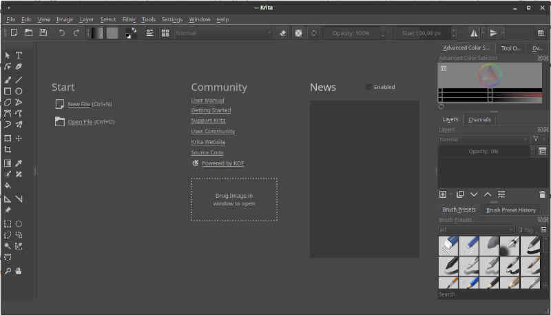
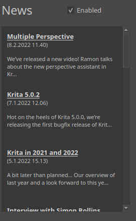
You immediately see Start, Community and News options in the middle of the screen. Start title has two options, New file and Open file. There is also a “Drag Image in the window to open”-option to open an image. Community title has a list of links to various documentation and support links listed below it. News option was blank, but it had an empty Enable checkbox right next to it. I selected the checkbox and the News feed opened. Obviously, the latest version of Krita is 5.0.2 instead of 4.2.9 installed in my distribution. Instead of installing the new one, I chose to continue with the older version and trust that there is a reason why installing Krita did install an older major version release.
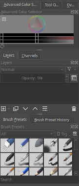
In the right side of the window there is an Advanced color selector with some kind of color selection interface. Tool options and Overview can be selected instead, but when clicked, both result in an empty area in the place of color selection interface. Below the selector, there is a Layers / Channels area. Layers selection shows 0% opacity in it and changing it wasn’t possible. Channels selection didn’t show anything. Probably this is because in the beginning there is no picture with those properties opened. As the names suggest, Krita supports Layers, making it possible to edit some layers only, leaving the others as they are. This is obviously a great thing when you are, for example, drawing animation. All the modern 2D drawing programs support layers. Channels support makes it possible to edit the color channels or alpha channel (transparency) separately. It is also possible to separate the channels to layers from the image. The third part, the lowest part of the left, there are brush presets and brush preset history. After reading the Krita manual, I found out that these sub-windows are called Dockers in Krita terminology.
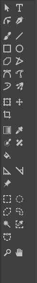
In the right side of the window there are icons for different 2D drawing options. Some of the icons look the same as in Paint and various other 2D drawing programs, some of the icons don’t look familiar.
On the top part of the window, there are the basic pull-down menus.
I selected “Help”-pull-down menu and chose About.
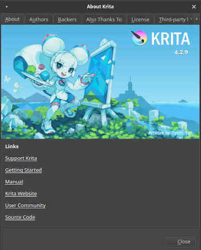
The screen opened has a link to Getting Started, so I decided to continue there and read some info in order to begin drawing something about my Final Project.
Drawing on Krita
I wanted to create a hexagonal polygon on Krita. After some searching, I found out that there is no direct support in Krita for drawing regular polygons. While browsing the forums I found out that the multi brush tool was suggested as a workaround The same forum threadalso suggested using Inkscape for drawing one and importing it. Another option mentioned is to make a vector library in Inkscape and import it to Krita.
I followed the multi brush tool lead. I found a video, How to use multibrush tool in Kritathe subject. The idea would probably have been to use the symmetry properties (a hexagon has six lines on symmetry and drawing the hexagon by hand mirroring the image by the axes. I didn’t think so. I decided to just do one in Inkscape and import it to Krita. I found a nice video about doing the hexagonal polygon in Inkscape.
In search for a hexagonal polygon - Inkscape
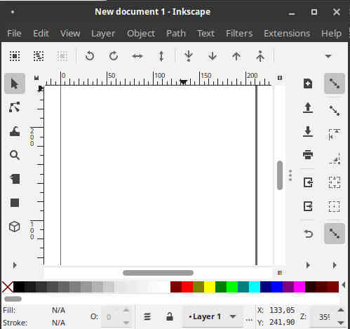
So, I opened Inkscape (which had already been installed in my system). A New document 1 - Inkscape window opened.
I looked around the window and found the “Create stars and polygons” tool.
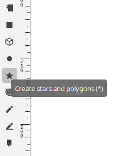
After selecting “Create stars and polygons tool, the icons above changed and I selected “Regular polygon (with one handle) instead of a star”
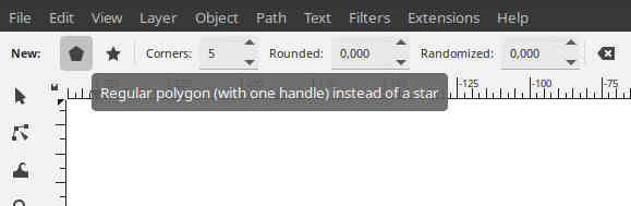
After some trying, I found the options leading to regular hexagonal polygon, instead of a star.
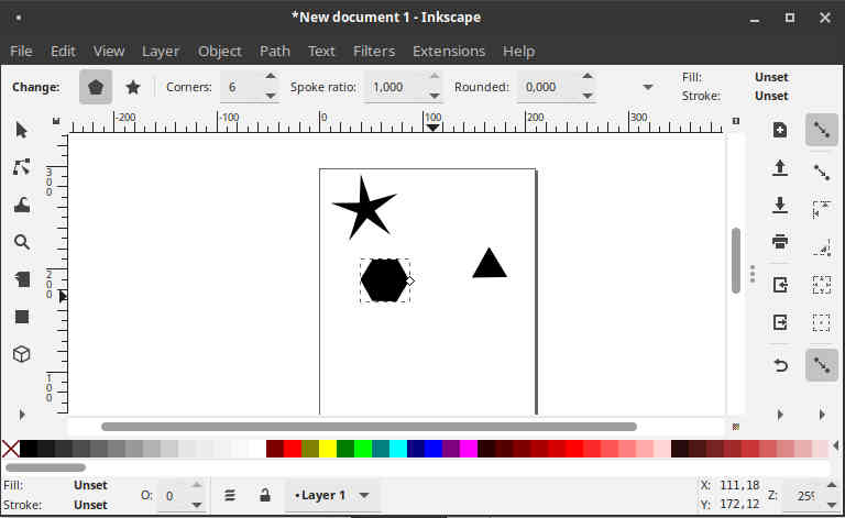
I removed the failed hexagons by undo. Then I drew a new one.
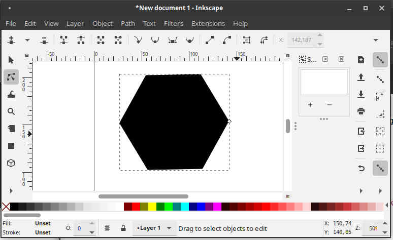
First I decided to follow the procedure I found. Then I noticed that the instructions were doing something else. I would actually need that later, but for now I decided to simply try copy-paste to Krita.
Drawing in Krita
In Krita I pressed Control-n to start a new drawing. A “Create New Document” window opened.
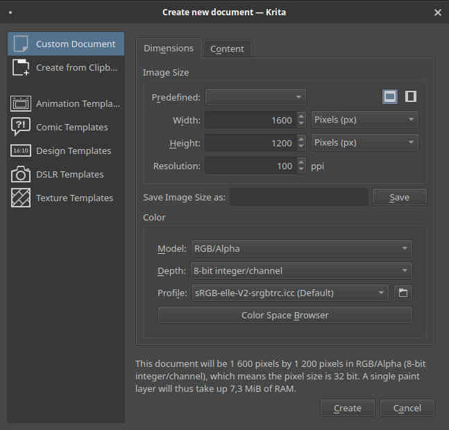
The values were fine by me, so I pressed Create. A new canvas appeared.
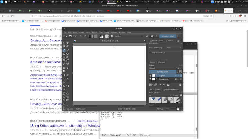
I noticed “not saved” text. Krita has an autosave feature.
Then I tried copy-paste and it worked.
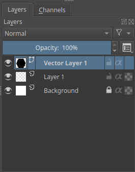
I checked the Layers Docker. It looks like that the copy-paste created “Vector Layer 1” to the image, so a copy-paste of vector graphics from Inkscape to Krita seems to work. This is good news.
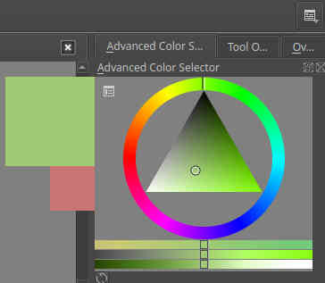
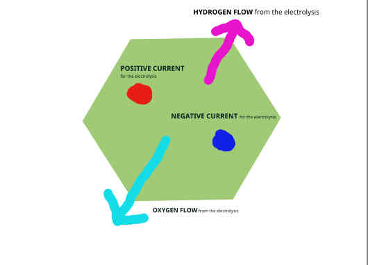
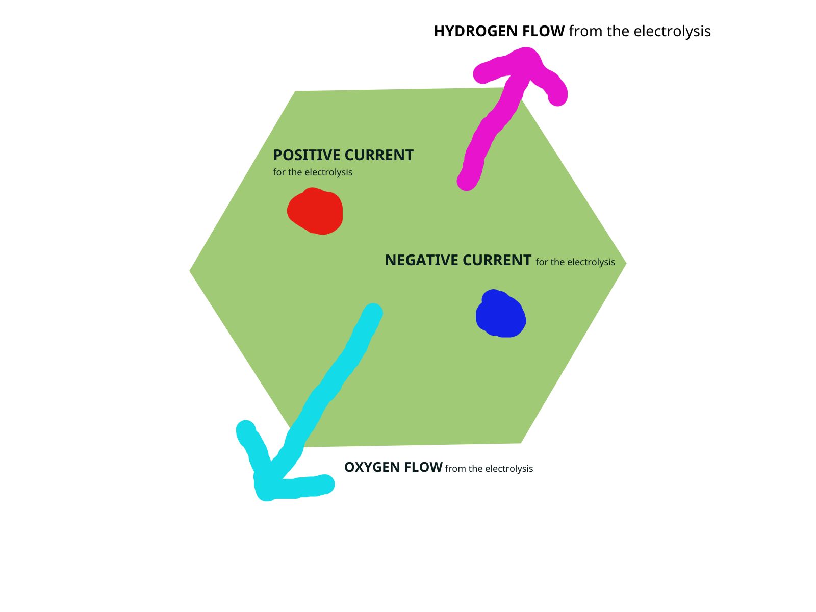
I changed the location of the hexagon to a better place by selecting the hexagon by mouse and using cut-paste. Then I used the Advanced Color Selector Docker to change the color of the Vector hexagon.
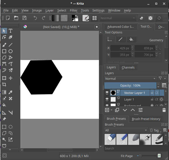
Then I created a new layer, added some text with the Text tool.
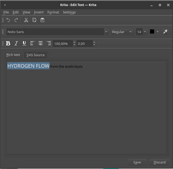
The final result of the Krita sketch can be seen in the image below.
I saved and exported the images in both programs. This concludes my tests in these teo programs.
Results
- The original Krita file in original .kra binary format.
- The exported Krita file in .jpg format.
- The original Inkscape file in .svg format.
- The exported Inkscape file in .png format.
It seems that the programs complement each other’s functionality. Moving vector data from Inkscape to Krita by copy-paste appears to work.
FreeCad (3D/2D)
FreeCad is a 3D Cad software, “parametric 3D CAD modeler” with 2D features. It also defines itself as a feature based parametric modeler. It is a multiplatform tool and it is open source.
I installed Freecad by typing
sudo apt-get install freecad
This installed FreeCad 0.18.4 Installation took about 576 MB.
After the installation, I started the program by typing the program name on command line:
freecad
Freecad opening screen opened.
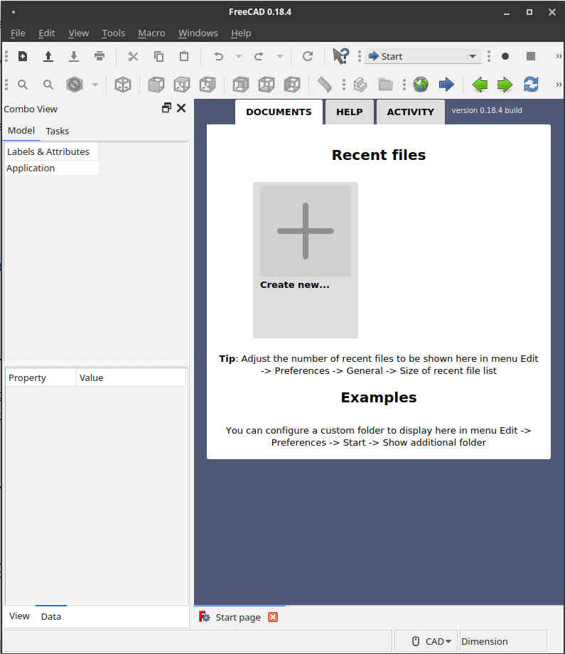
The opening screen had Document, Help and Activity selection. I checked the Help first. There was User hub for beginners, Power users hub for advanced users, Developers hub for free cad developers and then the actual Manual. E-book versions were also available.
According to the User hub info, there are multiple Workbenches in FreeCad. For example, Part Design Workbench is for small scale mechanical models. For 2D design, there are Draft WorkBench and Sketcher Workbench for defining constraints.
Testing FreeCad.
I chose File -> New for starting a new part. I chose the Part Design workbench.
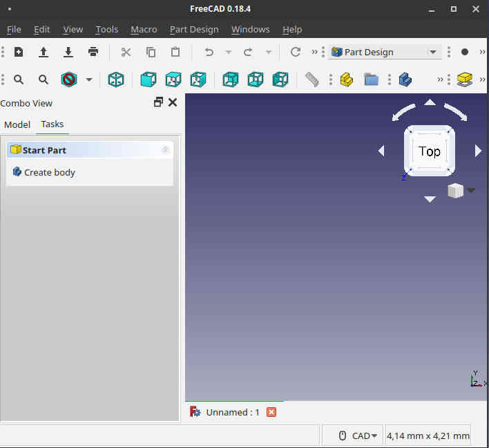
I pressed Create body from Combo View on the left and then pressed Create sketch in the appeared Start Body box. A XY_Plane001 appeared.
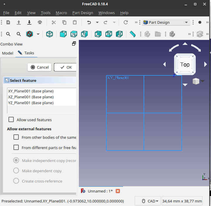
I selected the XY plane from the Select Feature box and pressed ok. Now I am drawing the sketch to the XY-plane.
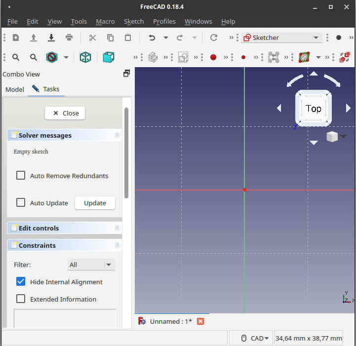
In the upper part of the screen there is a bar containing tools needed for drawing the sketch.

I select a hexagonal polygon from the polygon list.
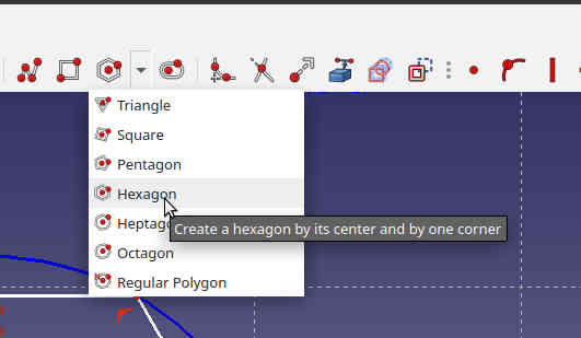
I drew a hexagonal polygon.
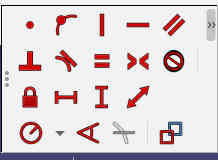
There is a list of constraints under the constraints list in the bar.
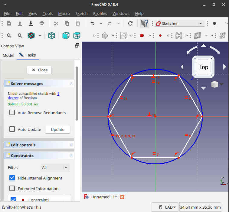
I selected constraints setting the center of the hexagonal polygon to the origin of the XY-plane. I also fix the position of the hexagon so, that there is 90 degree fixed angle between upper part of the hexagon an the y-axis. The position of the hexagon is now fixed. I tried to fix the distance between hexagon side and origo. Setting a constraint for distance between a line and a point appeared to be really hard to do. Also, setting a point to the midpoint of the line seemed hard to find as well. Fixing a distance between a corner point and origo was not something I wanted to do. So, I created a separate point in the sketch, and set constraints to it. I was afraid this might lead to an overconstrained sketch.
I finally managed adding a new point and constraining it to both the vertex of the hexagon and y-axis. Then I set the distance between the point and the origo.
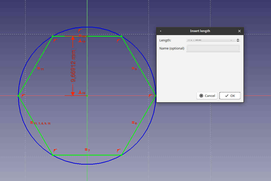
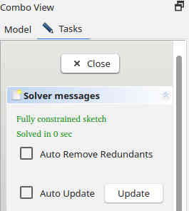
Unfortunately, the window opened didn’t let me set the distance, as seen in the picture. Obviously, there is a bug in the program. It is open source, so in principle I could fix the bug. However, I am evaluating if I could use this program for my final project. Finding out, that setting constraints for hexagonal shape is hard to do and that there are quite visible bugs in the program already helps me to do the decision. I deleted blinly everything there was and wrote 10 mm. After that I clicked the constraint again. This didn’t help, the field was still unreadable. I changed the value to 60 mm and zoomed the view so, that the sketch can be seen in the image.
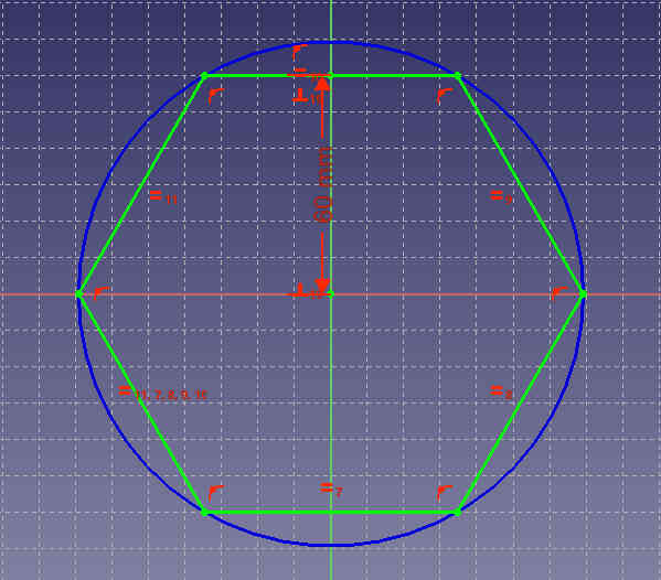
Solver messages showed that the sketch was fully constrained, so I closed the sketch.
Then, I somehow managed to destroy the draft. Undo/redo didn’t help, while I did something to clear the undo sequence. At this point, I took this as a 2D sketch evaluation, because the tool is also a recommended tool for 2D design on the lecture list, and decided to move on.
Results
No results recovered. I learned that the program has bugs and it is possible to lose all the work if the user is not careful or is unfamiliar with the program. This doesn’t raise the program high in my priority list.
OpenSCAD (3D)
OpenSCAD is programming language based CAD tool for Linux, Windows and MacOs. It is based on Constructive Solid Geometry model. I found the concept really interesting.
I watched an interesting Video about OpenSCADs properties. There is also Basics of Parametric Design video about OpenSCAD, which I also browsed through because of the parametric desing requirements.
Evaluation of OpenSCAD
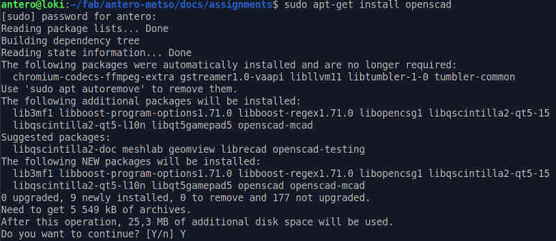
I installed OpenSCAD to Ubuntu.
sudo apt-get install openscad
This asked me to install a lot of extra components and I agreed.
I skipped the downloading.selecting, preparing, unpacking and setting up the components, because this is system-dependent and there was no user input required.
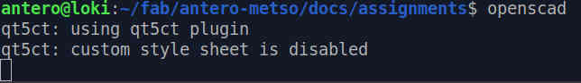
After that I started the program.
openscad
OpenSCAD started.
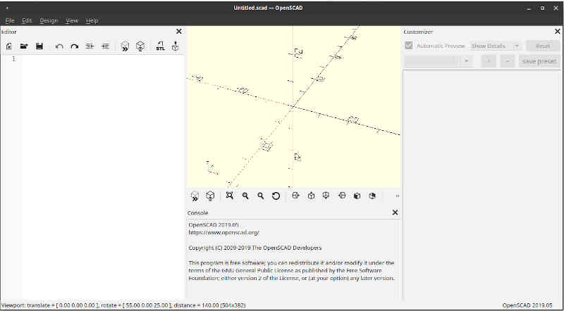
The welcome screen opened.
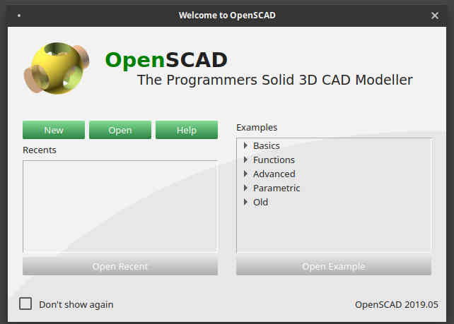
The help selection opened the external manual page. I spent some time browsing through the manual. According to the manual, “OpenSCAD is a solid 3D modeler that enables the creation of parametric models using its scripting language. Models are created by utilizing a technique called constructive solid geometry. According to this technique, simple objects can be transformed and combined in order to create almost any complex model. “
Creation of the model
I chose New selection next, and a new view opened.
Because there is still a lot of missing design in my final project, I decided to model a simple electrolysis chamber. I found the primitive solids from the user manual and began constructing a simple model of electrolytic chamber.
I found some help from 008 Prototype Enclosures with FreeCad & OpenSCAD by OpenTechlabvideo.
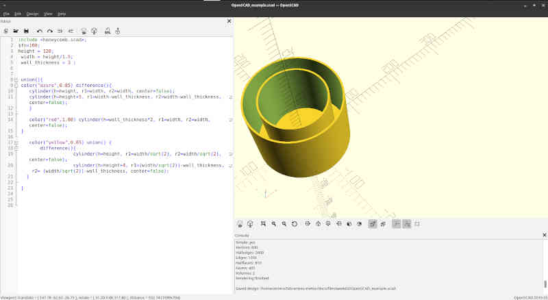
I wanted to try installing extra libraries and added a honeycomb library by Gaellafond from Thingiverse. I successfully added the library and managed to import it.
I tried to find an easy way to make holes / honeycomb to the separator between outer and inner part of the chamber and found out that there is no easy way. The programming language didn’t support that easy task directly without making a program to do that. I decided that the learning curve required was too deep and that’s why this tool is not suitable for the task. The scad file is included. Note the support for parametric design in the file.
The final view to the project:
Results
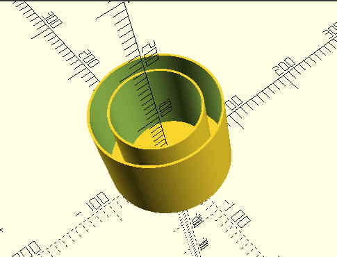
I was really disappointed with OpenSCAD. All the action is in the programming language. Even the rendering accuracy is set globally or for each command. I liked the flexibility this gives. However, the programming language support was worse than I expected. There is limited support for object oriented features and this alone kills the idea.
With higher level support for more modern features, the concept would work. Perhaps C++ based version would work better? It is also possible that the documentation was based on the older versions of the language with inferior support. Of course it is possible to do complex forms and parametric design with bare minimum variables and math support, but this is unnecessary pain.
My unfinished design is shown in the figure below.
OnShape (3D)
OnShape is a commercial professional quality closed source online CAD tool. It has extensive documentation and it has version control included. OnShape works on browsers. It means that browser shortcuts work on OnShape too. It is highly dependent on network connection. Student license was easy to get and it supports private and public work, when regular testing license allows only public work.
Evaluation of the OnShape
I started with watching the OnShape tutorials.
I created a student (edu) user on OnShape. I filled the registration and added mention of being a Fab Academy 2022 student tasked in selecting and evaluating a CAD program for the final project. I accepted agreements, clicked confirmation email, added the avatar picture and picked a nickname. Then I finally could start designing. However, the process was quite fast compared to installing a full CAD program on local drive.
Problem in Learning Tools
I tried to use learning tools, but I got a message stating that the tool requires purchase.

However, the next time I tried to use learning tools via an external link. They worked. So I browsed through OnShape fundamentals course pages.
Creation of the document
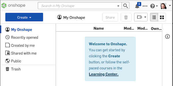
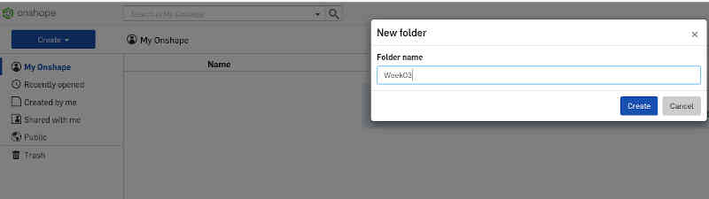
I created a new document folder, week03.
Then I moved to the new folder and created a new document.
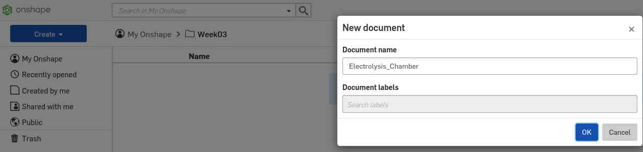
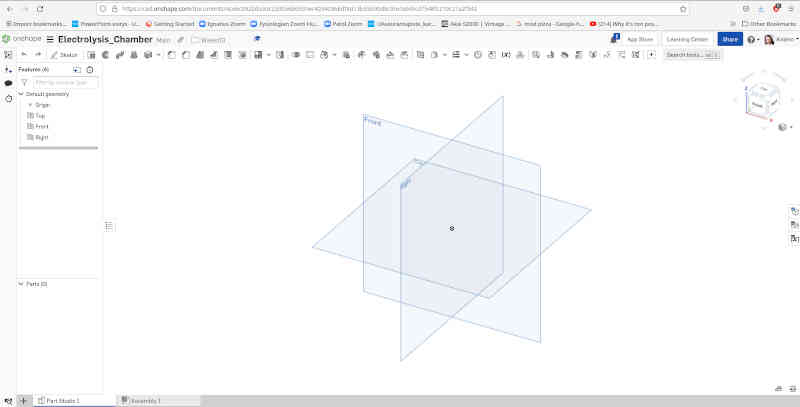
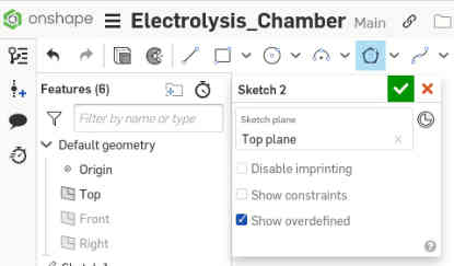
After creating a new document, a new view showing an empty canvas opened.
Testing OnShape workflow
I did testing as tasked. There were many things teste which are not documented here. I created two parts, bottom of the electrolysis chamber and top of the electrolysis chamber.
The chamber was done by first creating a sketch to top-plane. A hexagonal polygon was then drawn on the sketch.
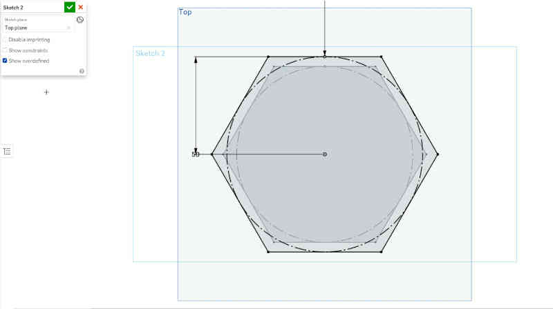
The polygon was drawn by selecting the polygon icon in the bar. The icons in the bar change according to the mode/application running and the polygon icon is visible in sketch drawing mode.
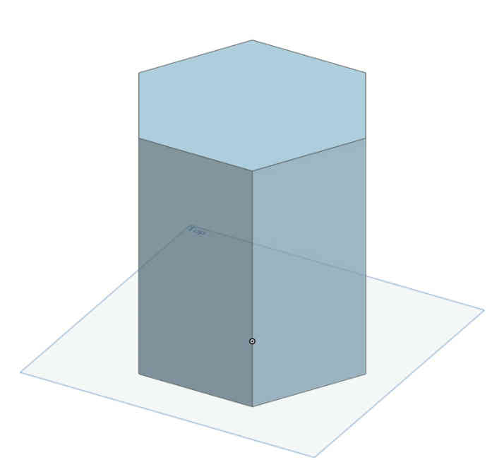
The polygon was then extruded to a hexagonal prism.
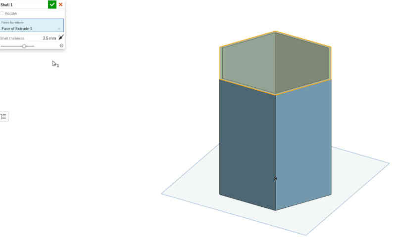
The hexagonal prism was then transformed to a shell. Thickness was set and the upper face of the hexagonal prism was removed in the process.
Then I created the second part (top) and started to create a border between oxygen and hydrogen parts of the gas generation chamber. I chose not to document this process here. The top part is going to be a lot more complex than it is now. This is what I have at this round of the spiral model.
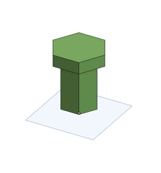
I experimented with different options for making a hole pattern into the top part by trying multiple times different filet / chamfer and linear pattern options.
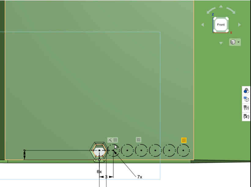
However, the learning curve was too deep for the purpose, so I decided that the evaluation of this tool is done. See the image for the final result.
Results
The original design files for OnShape are as follows:
Top OnShape file. Pool OnShape file. Top OnShape STL file. Pool OnShape STL file.
I found OnShape quite usable for the purpose. I liked the cloud based platform idea. It makes it possible to use the tool on multiple platforms. As with the OpenSCAD, there will be a point where learning slows down. I am a bit worried what happens, if there is no instructor support available for the program and the deadline is near.
Blender: Rendering and Animation (3D design, 2D video in this case)
Blender is a 3D computer graphics software toolset. It is open source and free. It does not support parametric modeling too well, so I didn’t do the design on Blender on scratch, but used it as a video rendering tool for designs made in OnShape. Blender is quite an advanced tool and it is considered difficult to master. I chose Blender as a tool for rendering and animation.
The version of Blender I used is 2.82 (sub 7). If you use older version of blender, like Blender 2.79, it is possible that the animation file generated does not work.
Blender and the state of my Final Project
Simulation for the final project is too early. The method for creating bubbles is not yet selected, there are design decisions to solve. I need to make tests in order to find a working way. In spiral model thinking, this model is very basic. However, rendering and animation is doable and is probably considered a simulation of how top moves from the bottom of the electrolysis chamber.
Importing the model
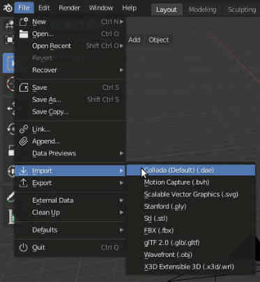
I chose to export the models from OnShape as .dae (Collada) models for Blender. The Export was done from the Parts list.
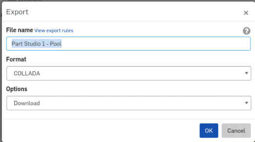
I imported the models to Blender.
Setting up the stage
I set up a light and adjusted camera, so that the image was correctly sized in the render display. It took me quite a few iterations to do it. I have used Blender earlier, but the UI always requires some time to learn again.
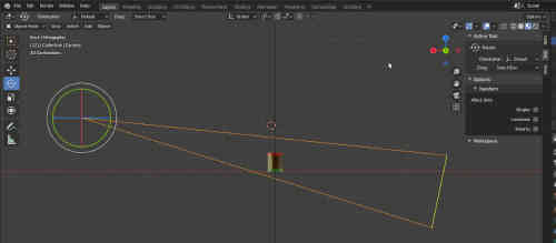
Setting up the camera view.
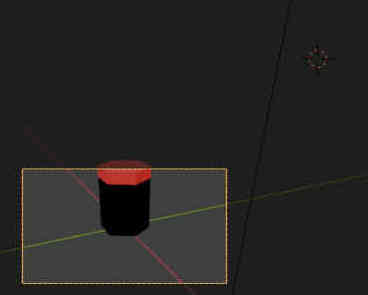
Setting up the camera, view from another direction.
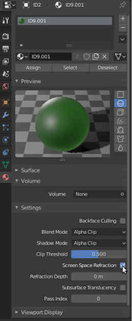
I created materials for the parts. Creating materials took some iterations. I used the more complex way first, requiring setting up the modules in the UI. Then I reverted back to the easier way, because the more complex models were really not required this time.
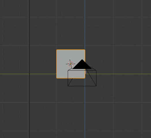
I added the floor.
Setting up the animation.
I set up the frame rate and resolution for the rendered video. There are other settings to consider here for more complex designs as well, but I took the shortest route.
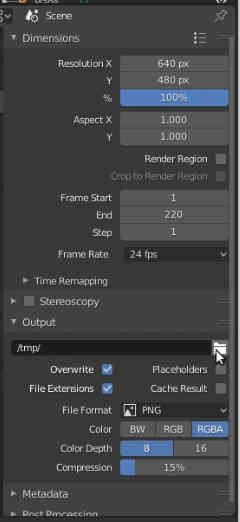
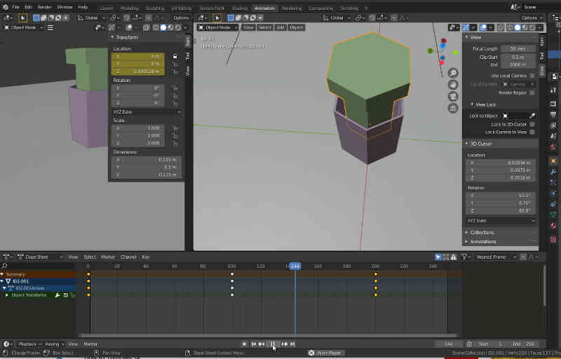
The animation set up was done in the rendering screen. There is a timeline bar, where the keyframes can be set.

I set three keyframes to the timeline. The set keyframes can be seen on the timeline bar. Changed keyframe can be set in the keyframe bar. The keyframes were set by first moving the object coordinates to the correct position, pressing ‘g’ and ‘z’ for z-coordinate. ‘n’ shows the location, ‘i’ creates a keyframe.
Then I initiated the Rendering. The image sequence was stored in the directory defined in the “set up the frame rate and resolution” page.
Results
The result was a set of png images, which I converted to mp4-video in ffmpeg. For me the rendering process took a few seconds per frame. The time depends on the resolution, settings and the complexity of the model. I won’t go into the details here, but the basic thing to understand is that the rendering process is not instantaneous. With a small model, today’s GPU power and software harnessing it, it might as well be. Historically, the rendering has taken a lot of time.
Because the images are kind of raw material for producing video and there are over two hundred of them, the images are not shown here. However, the Blender save file for the process, containing binary data, is included.
Blender file for Rendering Animation. Note that the file is for Blender 2.82.
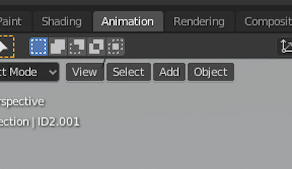
Select “Animation” tab to see the the animation desing.
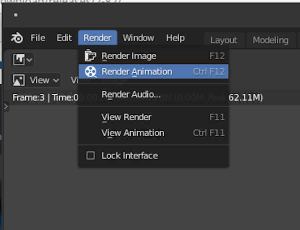
Select Render-> Render Video in order to test rendering the video.
Ffmpeg: Encoding the mp4-video (2D)
FFmpeg is usually able to decode, encode, transcode, mux, demux, stream, filter and play pretty much anything that humans and machines have created. Ffmpeg is a highly efficient command line tool.
I chose ffmpeg as a video creation tool because it is the most commonly used video tool in command line environments. There are some things that are difficult or impossible to do in ffmpeg, so I have also used other video tools. For command line video creation, ffmpeg is currently the standard tool.
Encoding mp4 video out of png image set
The video was created by writing first the following text to imagepath.txt:
file 'E:\images\png\%4d.png'
This line covered the set of filenames for the images, like 0001.png onwards. Ffmpeg was then started with the following command:
ffmpeg -framerate 24 -i %04d.png -vf format=yuv420p output.mp4
This encoded the mp4 video file out of the sequence of png images. yuv420p colorspace setting is there for compatibility reasons.
Results
The Video of the rising lid of the Electrolysis Chamber takes only 85.2 kilobytes of space. This result demonstrates the compression power of the Mpeg-4 family of codecs.
What did I learn?
I learned about OpenSCAD and the programming approach to CAD. It is promising, but as far as I understood, the programming language used is too limited for really quick design. Programming of these kinds of tools should be easy and flexible. Especially limited support for the object model sounded bad. If you have your own libraries or libraries you know how to use, this might be an effective tool. OnShape is an usable tool. It has a lot of online support, but learning it also takes a lot of time. Of those two I would use OnShape.
Inkscape and Krita complement each other. Copy-paste from Inkscape vector model works to Krita. The programs were made for different purposes.
Evaluating software is very time-consuming. However, I probably still should look for other alternatives.
I also refreshed my Blender skills in creating rendering animations. The screenshots were cut and sometimes scaled in Gimp, so while Gimp wasn’t evaluated, it was used too.
Final Project
I learned valuable skills for the final project. However, some of the tools evaluated are already part of my current standard workflow. I am looking forward to being able to make the design decisions so that I can actually start drawing the design. Setting up the Windows system for using advanced Design software (NX, Catia) is going to take so much time, that doing this week’s task didn’t allow me to do it, learn to use the advanced software nor advance the final project. However, there is still spring left and it is always nice to know more software.