Molding and Casting

Week 11

Assignments

Group assignment:
  • Review the safety data sheets for each of your molding and casting materials, then make and compare test casts with each of them.
Individual assignment :
  • Design a mold around the stock and tooling that you'll be using, mill it (rough cut + (at least) three-axis finish cut), and use it to cast parts.

Group assignment

As the previous weeks, I was in the group with Antti and Kenichi and we were supposed to try different materials and make a comparison of the results.

Figure 1. Different materials in Fablab Oulu.

After the lectures by the local instructors of the week, Gleb and Ari and explanations of the materials, safety and molding and casting process, we decided to try these materials in Fablab Oulu:

Because of working with different chemical products in this week, we were strongly recommended about safety issues including safety glasses and vinyl safety gloves (chemical-resistant) to prevent skin/eye irritation, and long sleeves or lab coats. For Smooth-Sil™ 940 and OOMOO™ 25, a properly ventilated area was also needed.

Smooth-Sil™ 940

With different hardnesses to choose from, Smooth-Sil™ products offer tremendous versatility and are suitable for making production molds of any configuration, large or small. These silicones exhibit good chemical, abrasion and heat resistance. Materials such as plasters, concrete, wax, low-melt metal alloys or resins (urethane, epoxy or polyester) can then be cast into these silicone rubbers without a release agent.

Smooth-Sil™ Platinum Silicones are used for rapid prototyping, wax casting (foundries and candle makers), architectural restoration and for casting concrete. Smooth-Sil™ 940 is suitable for food related applications.

Safety: Use in a properly ventilated area (“room size” ventilation). Wear safety glasses, long sleeves and rubber gloves to minimize contamination risk. Wear vinyl gloves only. Latex gloves will inhibit the cure of the rubber.

Figure 2. Safety comes first! Ventilation (left) and safety glasses and gloves (right)

Smooth-Sil™ 940 with a pink color is suitable for food related applications. Smooth-Sil™ 940 offers the convenience of a 100A:10B by weight mix ratio, pot life of 30 minutes and 24 hours cure time.

First, pre-mix Part B thoroughly to re-disperse pigments that may have settled.

Figure 3. Part A and B of Smooth-Sil™ 940.

Using a gram scale, dispense required amounts of parts A and B (100A and 10B) into a mixing container and mix for 3 minutes. Scrape the sides and bottom of the container several times.

Figure 4. Measuring and mixing part A and B of Smooth-Sil™ 940.

After mixing parts A and B, vacuum degassing is recommended to eliminate any entrapped air. Vacuum material for 2-3 minutes, making sure that you leave enough room in container for product expansion.

Figure 5. Vacuum degassing process

Then, pour the mixture to the selected mold and let it dry for 24 hours.

Figure 6. Pouring the mixture into the selected mold

OOMOO™ 25

OOMOO™ 25 is an easy to use tin cure silicone rubber compound that features a convenient one-to-one by volume mix ratio (no scale necessary). It has a low viscosity for easy mixing and pouring . . . vacuum degassing is not necessary. This product cures at room temperature with negligible shrinkage. OOMOO™ 25 has a 15-minute pot life and 75-minute cure time.

OOMOO™ 25 is suitable for a variety of art-related and industrial applications including making one and two-piece block molds for sculpture and prototype reproduction, casting plaster, resins and wax. OOMOO™ silicones are also suitable for electrical potting and encapsulation applications.

Figure 7. Part A and B of OOMOO™ 25

Safety: Use in a properly ventilated area (“room size” ventilation). Wear safety glasses, long sleeves and rubber gloves to minimize contamination risk. Wear vinyl gloves only. Latex gloves will inhibit the cure of the rubber.

Before you begin, pre-mix Parts A and B thoroughly. After dispensing equal amounts of Parts A and B into mixing container (100A:130B), mix thoroughly for 3 minutes making sure that you scrape the sides and bottom of the mixing container several times. Mixture should have a uniform color with no color streaks. If you observe color streaks, continue mixing until they are eliminated.

Figure 8. Mixing part A and B of OOMOO™ 25

Although OOMOO™ 25 did not need vacuum degassing, we did it!:D As you can see in Figure 9, it left porus on the surface and needed much time to complete while its pot life is short (15 minutes). So, we had to stop vacuum degassing and continue the process.

Figure 9. Vacuum degassing of OOMOO™ 25

Then, pour the mixture into the selected mold and let it dry (for 75 minutes).

Figure 10. Pouring OOMOO™ 25 into the selected mold

Smooth-Cast® 300

The Smooth-Cast™ 300 Series of liquid plastics are ultra-low viscosity casting resins that yield castings that are bright white and virtually bubble free. Vacuum degassing is not necessary. They offer the convenience of a 1A:1B by volume or 100A:90B by weight mix ratio. The differences between them are pot life and demold time.

Safety: These products have a limited shelf life and should be used as soon as possible. All liquid urethanes are moisture sensitive and will absorb atmospheric moisture. Mixing tools and containers should be clean and made of metal, glass or plastic. Mixing should be done in a well-ventilated area. Wear safety glasses, long sleeves and rubber gloves to minimize contamination risk. Because no two applications are quite the same, a small test application to determine suitability for your project is recommended if performance of this material is in question.

Stir or shake both Part A & Part B thoroughly before dispensing. After dispensing equal amounts of Parts A and B into mixing container (100A:90B by weight) and mix thoroughly. Stir deliberately making sure that you scrape the sides and bottom of the mixing container several times. Be careful not to splash low viscosity material out of the container.

Figure 11. Preparing Smooth-Cast® 300 mixture

Then, pour your mixture in a single spot at the lowest point of the containment field and let the mixture seek its level. This will help minimize air entrapment. Finally, let it dry (Smooth-Cast™ 300 will cure in 7 - 10 minutes).

Figure 12. Pouring Smooth-Cast® 300 into the mold

Cement (Creative-Knetbeton)

Under normal use product is not expected to be hazardous to the environment. It has an irritating effect on moist skin after prolonged contact. Eye contact with may cause serious injury, Inhalation of the large quantity of cement dust over a long period of time leads to lungs disease.

Figure 13. Creative-Knetbeton

First, mix 100gr of cement with 30 gr of water (we mixed 30 gr cement with 9 gr water).

Figure 14. Preparing cement mixture

Then, pour the mixture into the selected mold and let it dry (6-8 hours).

Figure 15. Pouring cement mixture into the mold

After curing

All of the molds with different materials were placed under the ventilator in the room to dry .

Figure 16. Putting the molds under the ventilator to dry

When the curing time for all of the materials was over, the pieces were unmolded. For removing Smooth-Sil™ 940, we needed to use air vaccuum.

Figure 17. Unmolding Smooth-Sil™ 940

OOMOO™ 25 was easily removed from the mold.

Figure 18. OOMOO™ 25 sample after curing

Smooth-Cast® 300 with its short curing time and cement were the easiest to be removed.

Figure 19. Unmolding Smooth-Cast® 300 sample

Figure 20. Molded cement after curing

Table 1 shows a comparison between the features of all of the used materials .

Table 1. Comparison of the used materials features

Individual assignment

3D Design

To design the mold, I decided to use Fusion 360 which I had worked with during the previous weeks. But I spent much time this week to find my desired design that was not good. I tried a couple of skecthes of different shapes and gave up in the middle... but at least, I got familiar with a couple of new features in Fusion 360:) So my best advice on this week is not to get stuck in design and also, consider the limitations of milling while preparing the design.

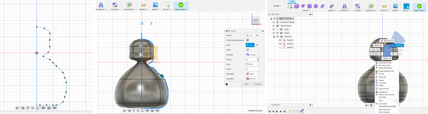
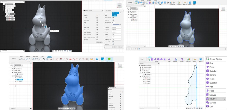
Figure 21. Desparately trying a couple of sketches!:D

Then, I started to draw a strawberry which is my favorite fruit and sounded simple. I had a look at the former students pages especially Zhengya who explained the steps in Fusion very well.

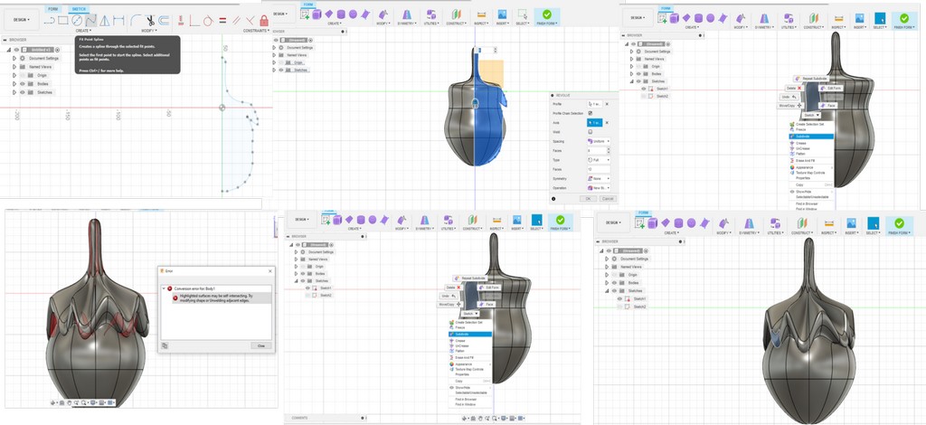
Figure 22. Drawing a strawberry in Fusion 360

But then, Gleb warned me to change the shape especially because of the leaves that might be struggling for milling:((

FINALLY, I decided to go with a safe option and design a spinner as it reminded me of one of my favorite movies and the most famous spinner:)

Figure 23. No caption!

For this, I started to download an image of a spinner and then, draw the sketch on it. I learnt this from those previous failed sketches and also, this tutorial!:D

First, press S to open "Sketch Shortcuts" and then, just type "c" to open Canvas and upload the image you want.

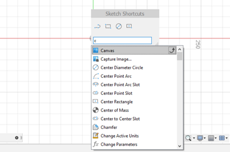
Figure 24. Uploading an image in Fusion 360

Then, from Fit Point Spline, I started to draw the lines around the image but only half of it.

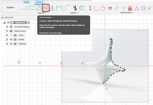
Figure 25. Drawing the sketch over an image in Fusion 360

After finishing the skecth, go to Create Form and then, select Revolve which creates T-spline body around the selected axis.

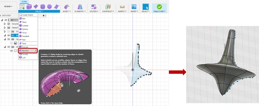
Figure 26. Revolving the sketch around the selected axis in Fusion 360

Actually, Gleb helped me a lot for the rest of process by showing me some new features and tips in Fusion. Here, I added an "Offset Plane" in the middle of the object by going to Construct->Extent->Distance (0.0. mm).

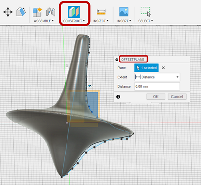
Figure 27. Adding an offset plane to the middle of the object

With this plane, splitting would be easier. Go to Modify->Split Body and then select the objest as the "Body to Split" and the midplane as "Splitting Tools".

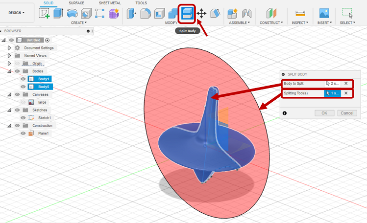
Figure 28. Splitting the body using a midplane as the splitting tool

Then, simply draw a box and go to Modify->Shell to create the molding box.

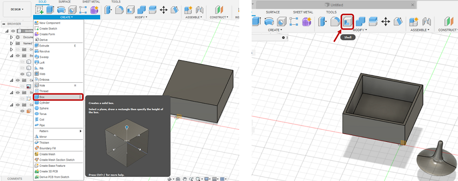
Figure 29. Creating the molding box

Next, make a small tilt in the walls of the box (10 degrees) by going to Modify->Draft and choosing the upper face of the box as "Pull Direction" and choosing the four walls of the box and setting Angle: 10.0 deg.

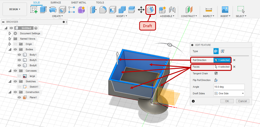
Figure 30. Making the walls of the box tilted by 10 degrees

To put the spinner inside the box, go to Modify->Align and choose the half-body for "From" and the lower face of the cube for "To" as Figure 31.

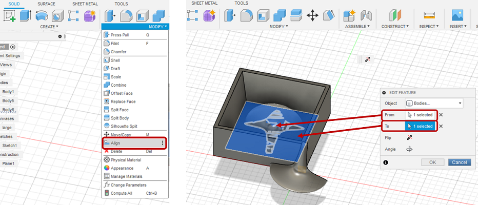
Figure 31. Putting the object inside the box by using Align feature

Then, go to Construct->Axis Perpendicular to Face at Point to add an axis in the center of the box and perpendicular to the lower face in order to facilitate for moving and rotating the object.

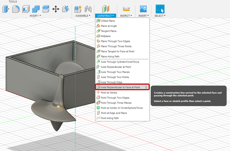
Figure 32. Creating an axis perpendicular to face at point

Next, to make sure that there is enough space from the shape to the walls of the box (minimum 3 mm becasue of the milling bit), I tilted the spinner around the axis I just made.

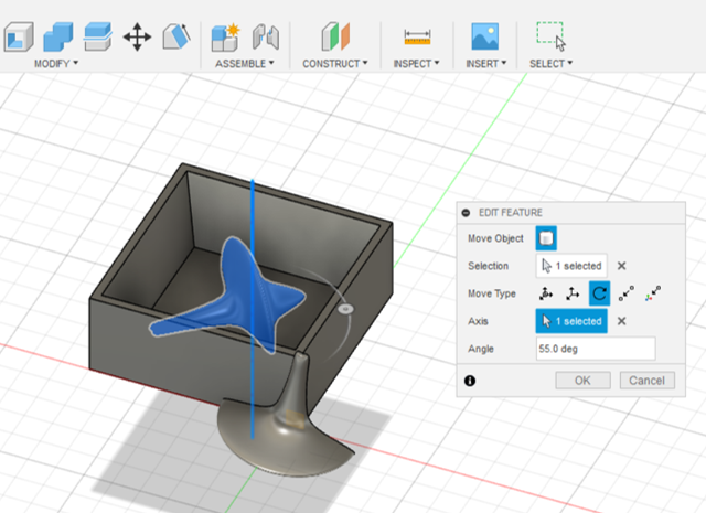
Figure 33. Rotating the object around the newly created axis to make enough space from the walls

Then, you should combine the box and the half of the spinner by simply going to Modify->Combine and select the objects and choose the operaton as Join.

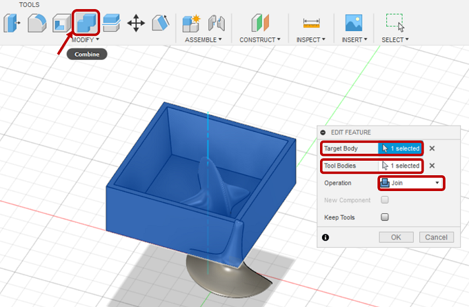
Figure 34. Combining the box and the spinner

Now, just Copy-paste the combined objects and make the other side of the box and also, go to Create->Mirror to mirror the shape on the other side of the box.

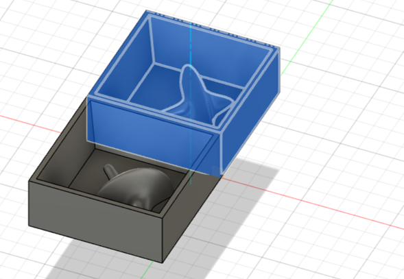
Figure 35. Copy-paste to create the other side of the box

Then, to create the pins for the casting box, I made the slots through Create->Slot->Three Point Arc Slot and mirroring the slots for the other side. Then, I went to Extrude and for one side, I extruded the slots 3mm while for the other side -3 mm.

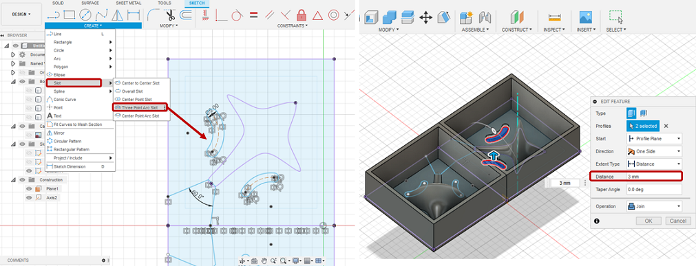
Figure 36. Creating the pins for the casting box

For pouring shaft, I drew two lines under the object sketch and a corner of the box with 60 degrees angle and then, exrtuded it (to 2.3 mm).

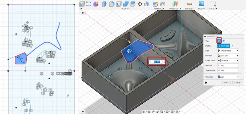
Figure 37. Making pouring shaft in the box

Then, go to Modify->Fillet and make the edges rounded by 2 mm.

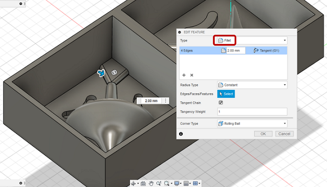
Figure 38. Fillet the edges of the pouring shaft

Finally, the molding box design is ready!

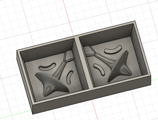
Figure 39. The final molding box

Creating roughing and finishing toolpaths

Here, the software for working with Roland SRM-20 is Modela Player 4 . First, I loaded the .stl file and then, change the origin through Options->Model->Origin from center to bottom corner left. Then, click New process from the right side.

Then, select the process type which this time was Roughing.

Next, you should select the tool which for roughing I chose 3 mm square milling bit.

For selecting cutting area, you can continue with the default which is All or choose Partial to speed up the process.

To selecet the type of tool path, contour lines and up cut were selected by default and I did not change them.

For tool parameters, I clicked initialize to have parameters loaded.

Then, from Modeling Form->Margin, I set 2 mm for all of the corners and from Depth, I set the top and bottom depth line.

Milling positive mold

For milling, I used Roland SRM-20 milling machine which I had used previous weeks. First, I chose the right milling bit that I set in the software. Then, to fix the wax box inside the machine milling board, I covered the wax and the board with the tape and applied hot glue to the bottom surface of the wax and put it on the board.

To control the milling machine, I used Vpanel software and set XY-origin to lower-left corner of the stock and Z-origin set to the surface. When milling finished, I cleaned the was and the postive molding was ready!

Here, I made a big mistake and remove the was before running finishing process!:'(

Casting Smooth-Sil 940

For casting, I chose Smooth-Sil 940 which has a mixing ratio of 100A:10B in weight.

I added 55 gr of part A and 65 gr of part B, mixing them and then, put the mixture in the vacuum degassing machine for a couple of minutes.

But then, I noticed the amount of the mixture would not be enough for the molding box!

So, I had to make more mixture to cover all of the box.

When, I was satisfied with the amount of casting mixture, I let it dry for about 24 hours.

After drying, I simply removed the casting from the box.

Then, I used Smooth Cast 305 and a syringe to fill the box through the pouring shaft.

But seems the material was not enough to cover the full shape! So, I got a half NICE spinner at the end!:D

Mona Peyvasteh

Fab Academy 2021

Diary of my journey to the world of Digital Fabrication